

Pentair SSM33IPC-1, SSM33IPV1, SRM4M1C, SSM33IPV1C, SRM4M2C Owner's Manual
...
OWNER’S MANUAL
Submersible Sump Effluent
SSM33I
SUMP/EFFLUENT PUMPS
(115 Volt-Single Phase Only)
293 WRIGHT STREET, DELAVAN, WI 53115 WWW.FEMYERS.COM
PH:
1-888-987-8677
© 2017 Pentair Ltd. All Rights Reserved. 13800A991 (09/08/17)
SUMP/EFFLUENT/SEWAGE PUMPS
(115 or 230 Volt-Single Phase)
SRM4
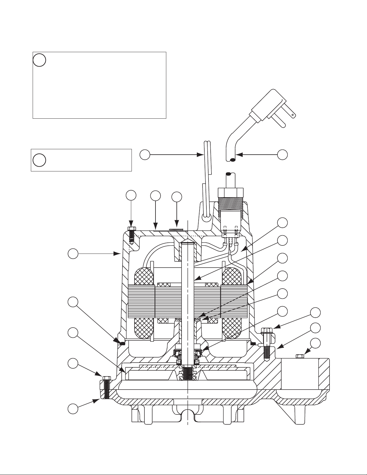
TYPICAL SECTION DRAWING FOR SSM33/SSM33I SERIES
20 Piggy-Back Control
Control Vertical Float Switch
10’ Cord
Control Vertical Float Switch
20’ Cord. Not Shown
(Automatic Only)
Cable Tie. Not Shown
21
(Automatic Only)
11
13
16
12
5
4
3
6
8
7
9
10
12
14
15
18
17
19
2
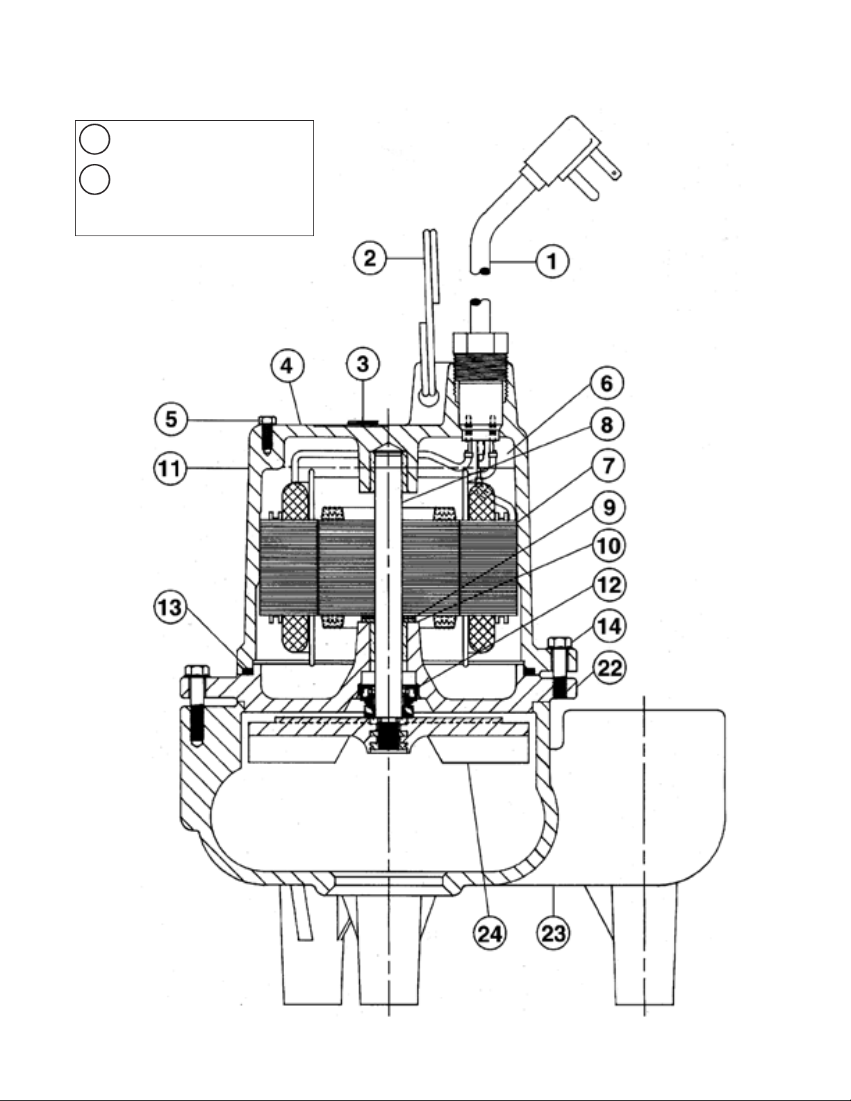
TYPICAL SECTION DRAWING FOR SRM4 SERIES
20 Piggy-Back Control
Cable Tie
21
Not Shown
(Automatic Only)
3
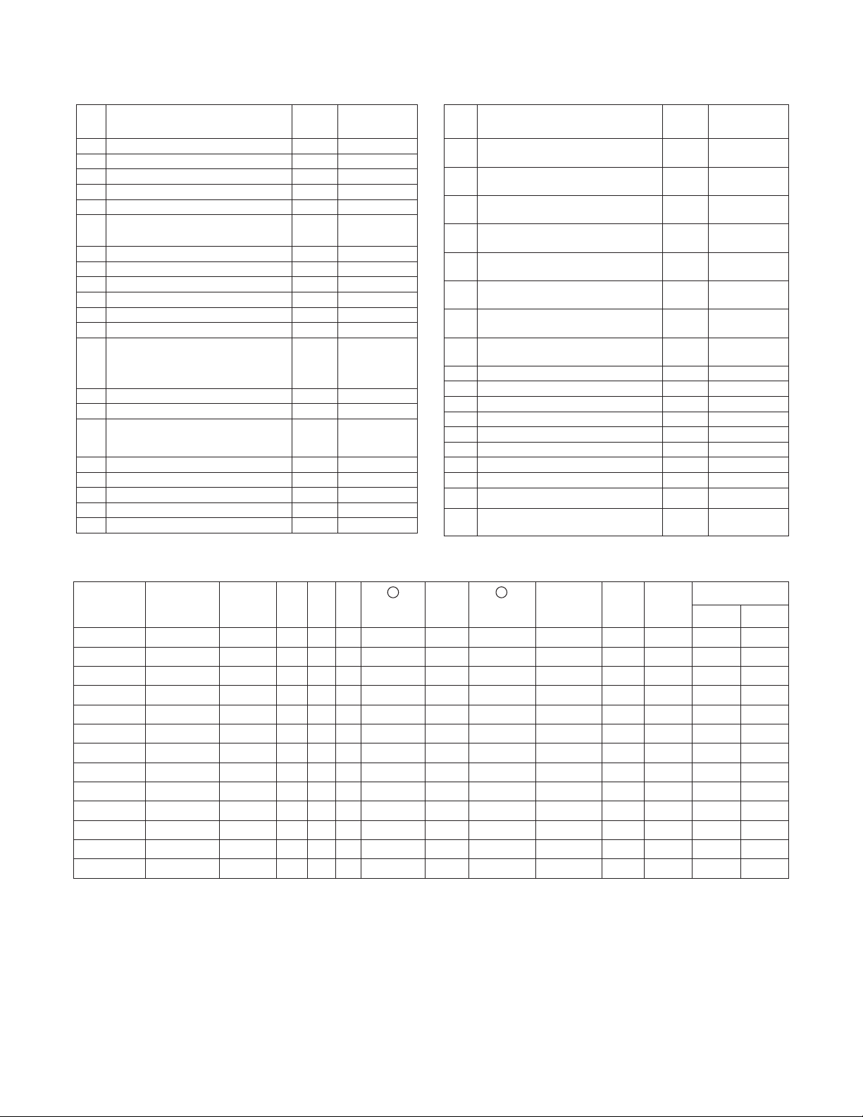
PARTS LIST SSM33/SSM33I AND SRM4
Ref
No.
No.
Description
Part
Req’d Numbers
2 Ring, Lift 1 26230A000
3 Plug, 1/4” NPT 1 05022A056
4 Plate, Name (Not Stamped) 1 23780A000
5 Tapping, Screw (SSM33/SSM33I) 1 09822A032
5 Tapping, Screw (SRM4P Auto.) 1 09822A006
Screw, Cap #10 x ¾ Vertical
5A
Float Switch
2 18475A004
6 Oil, Transformer (1 Qt. In Can) 1 11009A002
8 Rotor with Shaft (SSM33/SSM33I) 1 22821A010
8 Rotor with Shaft (SRM4) 1 22821A000
9 Washer, Thrust, SST 1 05030A243
10 Washer, Thrust, Graphite 1 05030A244
11 Housing, Motor 1 23770D002
Housing w/Stator
115V (SRM4P) 23770D060K
230V (SRM4P) 23770D061K
115V (SSM33/SSM33I) 23770D062K
12 Seal, ½” Shaft 1 21607A001
13 Gasket, Rubber 1 05014A172
14 Screw, Cap, 1/4-20 x 7/8 Lg.
(SSM33/SSM33I) 3 18475A003
(SRM4) 6 18475A003
15 Case, Volute (SSM33) 1 23771D001
15 Case, Volute (SSM33I) 1 23771D101
16 Impeller (SSM33) 1 22370B000
16 Impeller (SSM33I) 1 084980031
17 Plate, Bottom, with Volute Case 1 27005D000
Ref
No.
18 Screw, Tapping, #10 x 1” Lg.
No.
Description
Part
Req’d Numbers
3 09822A036
(SSM33, SRM4)
18 Screw, Tapping, #10 x ¾” Lg.
3 18475A008
(SSM33I)
19 Screw, Tapping, #10 x 1¾” Lg.
3 09822A040
(SSM33, SRM4)
19 Screw, Tapping, #10 x 1-5/8” Lg.
3 18475A009
(SSM33I)
20 Control, Level, 115V, 10’
1 21813B130
Piggy-Back Float Switch
20 Control, Level, 115V, 20’
1 21813B131
Piggy-Back Float Switch
20 Control, Level, 230V, 10’
1 21813B132
Piggy-Back Float Switch
20 Control, Level, 230V, 20’
1 21813B133
Piggy-Back Float Switch
20 Vertical Control Switch - 10’ Cord 1 26292B140
20 Vertical Control Switch - 20’ Cord 1 26292B141
20 Diaphragm Control Switch - 20’ Cord 1 149740195-01
20A Mounting Bracket, Control Switch 1 26291B010
21 Tie, Cable 1 17190A008
22 Plate, Seal (SRM4) 1 23773D002
23 Case, Volute (SRM4) 1 21612D000
24 Impeller (SRM4) 1 21610B000
Not
Bracket, Float (SSM33/SSM33I) 1 24003A000
Shown
Not
Bracket for Diaphragm
Shown
(SRM4D-1 Only)
1 055020111
CHART
Pump
Catalog
Number
SSM33IM1C 26235D100 Manual 1/3 115 1 21628B048 20' 22757B010 1.3 9 12.5 - -
SSM33IP-1 26235D110 Automatic 1/3 115 1 21628B046 10' 22757B010 1. 3 9 12.5 9 - 15/16" 4 - 1/16"
SSM33IPC-1 26235D111 Automatic 1/3 115 1 21628B048 20' 22757B010 1.3 9 12.5 9 - 15/16" 4 - 1/16"
SSM33IPV1 26235D120 Automatic 1/3 115 1 21628B046 10' 22757B010 1.3 9 12.5 5 - 7/8" 1 - 3/4"
SSM33IPV1C 26235D121 Automatic 1/3 11 5 1 21628B048 20' 22757B010 1.3 9 12.5 5 - 7/8" 1 - 3/4"
SRM4M1C 26236D001 Manual 4/10 11 5 1 21628B048 20' 21599B026 1.2 12 16 - -
SRM4M2C 26236D003 Manual 4/10 230 1 21628B049 20' 21599B027 4.3 6 8.2 - -
SRM4P-1 26236D010 Automatic 4/10 115 1 21628B046 10' 21599B026 1. 2 12 16 13 - 7/8" 8 - 1/8"
SRM4PC-1 26236D011 Automatic 4/10 115 1 21628B048 20' 21599B026 1. 2 12 16 13 - 7/8" 8 - 1/8"
SRM4PC-2 26236D013 Automatic 4/10 230 1 21628B049 20' 21599B027 4.3 6 8.2 13 - 7/8" 8 - 1/8"
SRM4V-1 26236D041 Automatic 4/10 115 1 21628B048 20' 21599B026 1. 2 12 16 6 - 1/4" 2 - 7/8"
SRM4V-2 26236D043 Automatic 4/10 230 1 21628B049 20' 21599B027 4.3 6 8.2 6 - 1/4" 2 - 7/8"
SRM4D-1 26236D061 Automatic 4/10 11 5 1 21628B048 20' 21599B026 1. 2 12 16 11" 3"
Pump
Engineering
Number
Pump
Switch HP V Ph
1
Cord,
Electric
Cord
Length
7
Stator
Only
Winding
Resistance
in Ohms
Max.
Amps
Locked
Rotor
Amps
Switch
On Off
4

NOTE: READ THESE INSTRUCTIONS
CAREFULLY BEFORE ATTEMPTING TO
INSTALL PUMP.
DESCRIPTION AND APPLICATION
SSM33, SSM33I and SRM4
Myers SSM33, SSM33I and SRM4 Series Pumps are single
seal units, available in automatic or manual. The SSM33 and
SSM33I series pumps are designed for normal sump and
dewatering, and can also be used in effluent applications.
When used in effluent dosing or S.T.E.P. applications,the
pump must be installed in a separate tank or compartment
at the discharge side of the septic tank. NEVER INSTALL
PUMP IN MAIN TANK WHERE SLUDGE COLLECTS. DO
NOT USE THE SSM33 OR SSM33I PUMP SERIES FOR
RAW SEWAGE. The SRM4 series pumps are designed for
residential sewage and dewatering applications where a
larger solid size is required.
LEVEL CONTROLS
The automatic models come with 10’ or 20’ power cord and
mechanical (mercury free), piggy-back float switch. The 115
or 230 volt piggy-back switch is tethered directly to the pump.
The switch can optionally be mounted to the discharge pipe
using a minimum 3-5/8” tether length. The switch must float
free from pump and basin wall. Plug the switch cord plug
into a properly grounded, rated voltage receptacle. Plug the
power cord into the back of the switch cord and tape the
cords to the discharge pipe every 12”. The power receptacle
must be located outside the wet sump or basin due to the
DANGER of current leakage.
On all duplex units or simplex installations with additional
options like high water alarm, the power cord plug must be
cut off and wired into a control panel or into a sealed junction
box if used in wet sump or basin. The AWS-1 control also
acts as a sealed junction box for connecting power cord to
pump cord.
General
The SSM33, SSM33I and SRM4 pumps use shaded pole,
1550 RPM motors. SSM33 and SSM33I are available in 115
volt only and the SRM4 is available in 115 or 230 volt and
all are single phase only. Both the manual and automatic
models come standard with a 10 ft. power cord. A 20 ft. cord
and switch length are optionally available. All automatic
models come with a mechanical (mercury free) piggy-back
float switch or a vertical float switch. The SSM33 and SSM33I
pumps are designed to handle 1/2” spherical solids and have
a 1-1/2” NPT discharge threading. The SRM4 pumps are
designed to handle 2” spherical solids and have a 2” NPT
discharge threading. The SSM33, SSM33I and the SRM4
use an engineered thermoplastic vortex impeller designed to
efficiently produce the required pressures and flows.
WARNING! THESE PUMPS ARE NOT APPROVED FOR,
AND SHOULD NOT BE USED IN SWIMMING POOLS,
FOUNTAINS OR PUMPING POTABLE (DRINKING)
WATER.
AIR LOCKING
A pump is said to be air locked if water traps air in the
pump and it cannot get out, thus preventing the pump from
operating.
The SSM33, SSM33I and SRM4 sump pumps have a 1/16”
air vent hole in the impeller chamber to let out trapped
air. If this hole becomes plugged, pump may air lock. As a
secondary precaution a 1/8” hole should be drilled in the
discharge pipe below the check valve. The check valve
should be 12 to 18 inches above pump discharge. Do not put
check valve directly into pump discharge opening.
PACKAGING
Each pump is packaged separately in a carton marked with a
catalog number and Myers engineering number. The pumps
are carefully packaged to prevent damage in shipping.
However, occasionally damage may result due to rough
handling. Carefully go over the pump and check for damage
that could cause the pump to fail.
DESIGN OF PRESSURE SEWER SYSTEMS
Myers has available complete computer SOFTWARE for
designing PRESSURE SEWER SYSTEMS. This gives pipe
sizes to use and gives exact flow from any pump or group of
pumps in the system when operating simultaneously.
This design DISK for IBM® or COMPATIBLE computers is
available to engineers on request.
MOTOR TYPE
The motors used in these pumps are pressed into the cast
iron housings and surrounded by dielectric oil for superior
heat transfer. Both models use a shaded pole, 1550 RPM
motor. The SSM33 and SSM33I are rated at 1/3 HP and
the SRM4 is rated at 4/10 HP. All units have class A motor
insulation. SSM33 and SSM33I are available in 115 volt,
single phase only and SRM4 is available in 115 or 230
volt, single phase. All have overload protection, and use a
double sleeve bearing design. These pumps have no starting
switches and do not require a control panel for simplex
installation.
SAFETY WARNINGS
WARNING: Risk of electric shock. Pumps are supplied with
a grounding conductor and grounding-type attachment plug
on the power cord. To reduce the risk of electric shock, be
certain that it is connected only to a properly grounded,
grounding-type receptacle. DO NOT cut off ground pin or use
an adapter fitting. DO NOT use an extension cord with this
pump.
All pumps have a GROUND WIRE that is connected to the
motor. This wire goes to the receptacle or control panel which
must be connected to a good outside GROUND.
When wiring this pump follow all local electrical and safety
codes and ordinances as well as the most recent National
Electric Code (NEC-ANSI/NFPA 70).
CALIFORNIA PROPOSITION 65 WARNING:
This product and related accessories
contain chemicals known to the State of California to cause
cancer, birth defects or other reproductive harm.
5

CSA APPROVED
All pumps have CSA approval. Myers is a SSPMA certified
pump member.
INSTALLATION
WARNING: Basin or tank must be vented in accordance with
local plumbing codes. These pumps are not designed for and
CANNOT be installed in locations classified as hazardous in
accordance with the National Electric Code ANSI/NFPA 70.
CAUTION: Never enter pump chamber after sewage or
effluent has been in basin. Sewage water can give off
methane, hydrogen sulfide and other gasses which are
highly poisonous. For this reason, Myers recommends
installing effluent pumps with a quick removal system. The
quick removal system may be a union or coupling if the pipe
or discharge hose is within reach from the surface, or a rail
system type quick disconnect on deeper installations. See
installation drawings for suggested installation.
The dosing tank or pumping chamber must be constructed
of corrosion resistant materials and must be capable of
withstanding all anticipated internal and external loads. It
also must not allow infiltration or exfiltration. The tank must
have provisions for anti-buoyancy. Access holes or covers
must be adequate size and be accessible from the surface to
allow for installation and maintenance of the system. Access
covers must be lockable or heavy enough to prevent easy
access by unauthorized personnel. The pumping chamber
holding capacity should be selected to allow for emergency
conditions.
The discharge pipe must be the same size as the pump
discharge 1-1/2” for SSM33 and SSM33I, 2” for SRM4 or
larger. In order to insure sufficient fluid velocity to prevent
any residual solids from collecting in the discharge pipe, it
is recommended that a minimum flow of 2’ per second be
maintained. (12 GPM through 1-1/2” pipe, 21 GPM through
2” pipe and 46 GPM through 3” pipe). It is recommended that
PVC or equal pipe is used for corrosion resistance. A full flow
(ball or gate) shut off valve must be installed to prevent back
flow of effluent if the pump must be removed for service. A
check valve must be installed on pressure sewer systems
and on other systems where conditions allow to prevent
backflow and to reduce wear on the pump system.
A high water alarm must be installed on a separate circuit
from the pump circuit. The alarm should have the ability to be
tested for proper operation.
POINTS TO CHECK IF PUMP DOES NOT
RUN OR DOES NOT RUN PROPERLY
(1) Pump does not run or start when water is up in tank.
(a) Check for blown fuse or tripped circuit breaker.
(b) Check for defective level switch
(c) Where control panel is used be sure H-O-A switch is
in the AUTO position. If it does not run, turn switch
to the HAND position and if the pump runs then the
trouble is in the automatic electrical system. Have
ELECTRICIAN make electrical checks.
(d) Check for burned out motor. Occasionally lightning
can damage a motor even with lightning protection.
(e) Where plug-in cords are used be sure contact blades
are clean and making good contact. DO NOT USE
PLUG-IN CORDS INSIDE A SUMP OR WET WELL.
(f) Level control ball or weight may be stuck on side of
basin. Be sure it floats freely.
(2) Pump runs but does not deliver flow.
(a) Check for airlock. Start and stop pump several times,
if this does not help it may be necessary to loosen a
union in the discharge line to relieve airlock.
(b) Check valve may be installed backwards. Check flow
arrow on valve body. Check shut-off valve. It may be
closed.
(c) Check vertical elevation. It may be higher than pump
can develop. (See pump curve).
(d) Pump inlet may be plugged. Remove pump to check.
CAUTION: ALWAYS UNPLUG POWER CORDS OR TURN
OFF ALL MAIN AND BRANCH CIRCUIT BREAKERS
BEFORE DOING ANY WORK ON THE PUMP. If control
panel is remote from pump, disconnect lead wires to motor
so that no one can turn the circuit breaker back on.
BEFORE DISMANTLING PUMP FOR
REPLACEMENT OF PARTS
Clean pump thoroughly. Knock off all scale and deposits.
Submerge complete unit on Clorox solution for one hour
before taking apart.
6
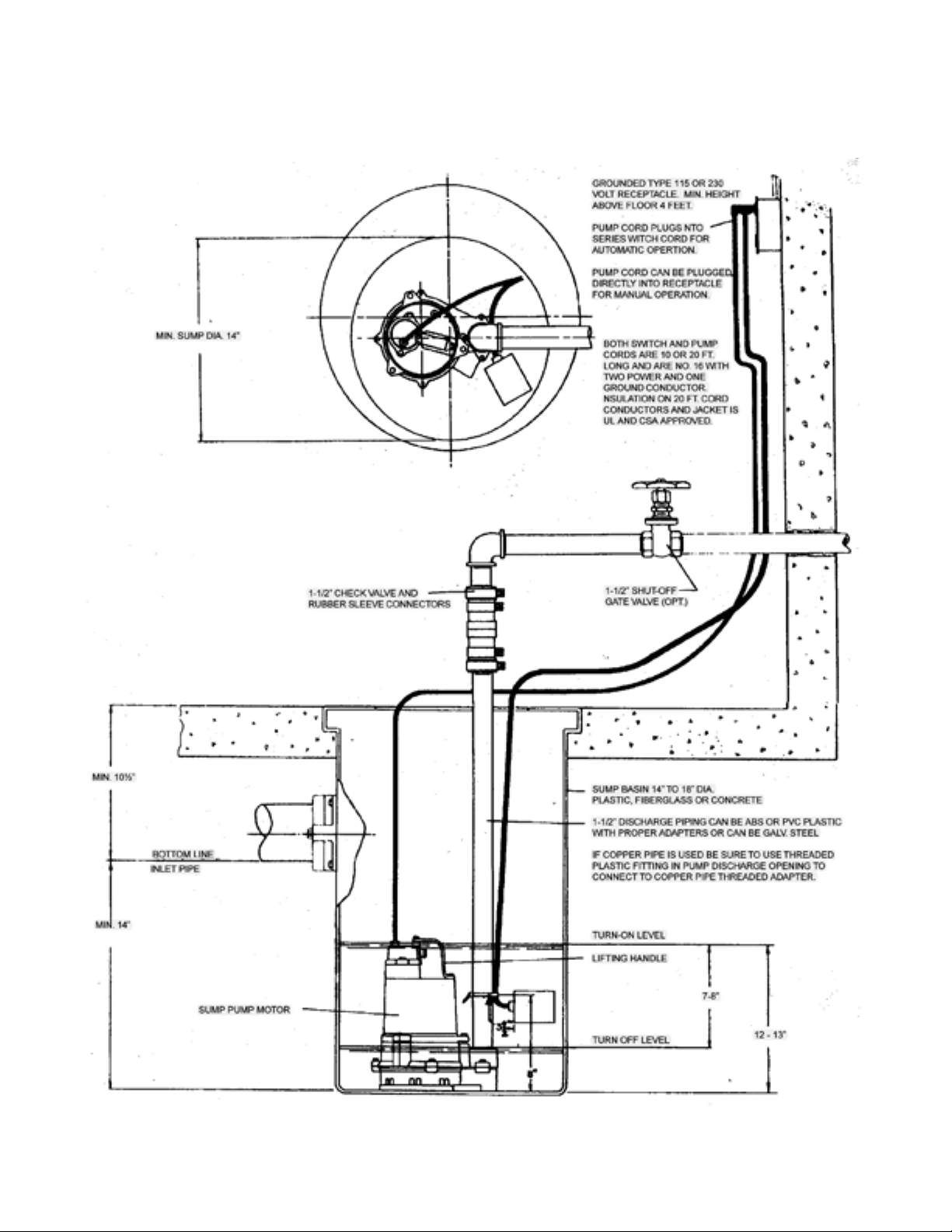
TYPICAL SUMP INSTALLATION FOR SSM33/SSM33I Series
7

TYPICAL SUMP INSTALLATION FOR SRM4 SERIES
8
 Loading...