

InstallatIon and servIce Manual
SPD50H/100H
Submersible Effluent Pump
NOTE! TO THE INSTALLER: Please make sure
you provide this manual to the owner of the
pumping equipment or to the responsible party
who maintains the system.
293 WRIGHT STREET, DELAVAN, WI 53115 WWW.HYDROMATIC.COM
PH: 888-957-8677
269 TRILLIUM DRIVE, KITCHENER, ONTARIO, CANADA N2G 4W5
PH: 519-896-2163
© 2013 Pentair, Ltd. All Rights Reserved. W-03-193 (Rev. 03/04/13)

General
Information
Thank you for purchasing your
HYDROMATIC
ensure years of trouble-free
op er a tion, please read the
fol low ing manual carefully.
Before Operation:
Read the following in struc tions
care ful ly. Reasonable care and
safe meth ods should be practiced.
Check local codes and requirements before installation.
Attention:
This manual contains important
information for the safe use of
this product. Read this manual
completely before using this
product and refer to it often for
con tin ued safe product use.
DO NOT THROW AWAY OR
LOSE THIS MAN U AL. Keep
it in a safe place so that you may
refer to it often.
WARNING: Before handling
these pumps and controls,
always disconnect the power
first. Do not smoke or use
sparkable electrical devices or
flames in a septic (gaseous) or
possible septic sump.
California Proposition 65
Warning
related accessories contain
chemicals known to the State of
California to cause cancer, birth
defects or other reproductive harm.
®
pump. To help
This product and
Pump
Warning
To reduce risk of electrical
shock:
1. Risk of Electrical Shock:
This pump has not been
in ves ti gat ed for use in
swimming pool areas.
2. Risk of Electrical Shock:
Connect only to a properly
ground ed receptacle.
Septic tank to be vented in
ac cor dance with local
plumbing codes.
Do not smoke or use sparkable
electrical devices or flame in
a septic (gaseous) or possible
septic sump.
If a septic sump condition
exists and if entry into sump
is necessary, then (1) provide
proper safety precautions
per OSHA re quire ments and
(2) do not enter sump until
these precautions are strictly
adhered to.
Do not install pump in location
clas si fied as hazardous per
N.E.C., ANSI/NFPA 70 -
2001.
Failure to heed above cautions
could result in injury or death.
Pump
Installation
These important instructions
mustbe followed for satisfactory
per for mance of your pump:
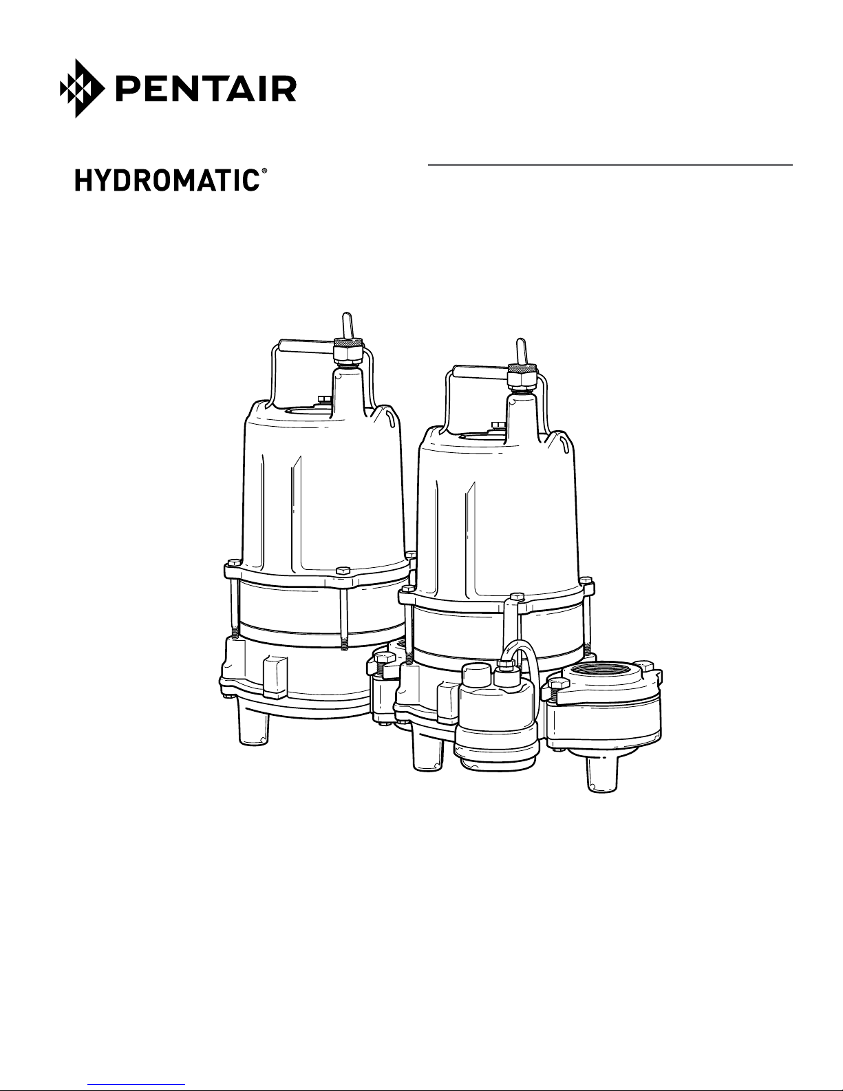
1. Provide proper sump
(rec om mend ed minimum
sump diameter is 30").
2. Do not set pump directly on
the bottom of sump if it is
not solid. Raise the pump by
using bricks or concrete
blocks un der neath it.
3. Make sure sump is free of
string, cloth, nails, gravel, etc.
before installing pump.
4. Risk of electrical shock —
connect only to a properly
grounded receptacle.
5. Do not remove ground pin
from electrical plug.
6. Do not use an extension cord.
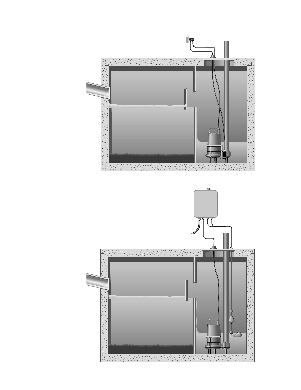
7. For proper automatic operation,
make sure the pump power
cord is plugged into the
piggyback receptacle on the
diaphragm switch cord.
8. Connect to separate electrical
circuit taken directly from
main switch.
9. Use steel or plastic pipe for
all connecting lines between
pump and sewer outlet.
Note: Some city regulations
do not allow installing a
pump with plastic pipe.
Check local reg u la tions.
10. In applications in which the
pump may sit idle for months
at a time, it is rec om mend ed
that the pump(s) be cycled
every month to ensure the
pumping system is working
properly when needed.
11. HYDROMATIC check valve
should be installed in
discharge pipe.
12. An audible alarm system such
as the Q Alert (indoor use
only) for high water con di tions
should be installed in every
pump for greater protection.
Contact your HYDROMATIC
distributor for ad di tion al
panel applications.
Warning: When using the
automatic diaphragm switch,
the vent tube in the plug
must be clear of obstructions.
Do not bend cord. This will
cause a crimp in the vent
tube and switch failure
will occur. Pump should
be plugged into a single
outlet, where vent tube
can “breathe.” Blocking
tube or bending cord will
void the warranty.
2

Pump
Servicing
Read the following instructions
carefully before replacing any
parts. Reasonable care and safe
methods should be practiced.
Check local codes and
requirements before installation.
Only a com pe tent electrician
should make the installations.
Tools Required
General shop tools include socket
wrenches and a bearing puller.
An ohmmeter is required
to thoroughly check motor
and wiring.
For proper au to mat ic op er a tion,
make sure the pump power
cord is plugged into the piggy back re cep ta cle on the float
switch cord.
Before removing the pump from
its installation for repairs, check
first to see if the trouble is
caused by:
1. Miswiring of the pump into
the terminal block.
2. Miswiring of the float level
controls into the panel.
3. Miswiring inside the control
panel.
4. Trip circuit breaker. If the
breaker is manually reset and
then trips off again, the
problem could be:
a. short circuit in motor or
control panel
b. water in the motor housing
c. insufficient amp capacity of
wiring or breakers
d. improper panel wiring
5. Tripped overload. If overload
is manually reset and then
trips off again, the problem
could be:
a. pump or piping is clogged
b. pump motor or bearings
may be defective
c. start capacitor in motor may
have failed
d. pump may be miswired to
terminal block
e. head is lower than rating,
pumping too much liquid
6. Air locked pump. Disconnect
piping at union and run until
all air bubbles are expelled.
7. Wrong impeller rotation.
Ro ta tion should be coun terclock wise when looking at
the impeller. Correct improper
rotation on three phase pumps
by reversing any two line
leads. No rotation check is
nec es sary on single phase pumps.
8. Closed discharge gate valve.
9. Plugged impeller or pipeline.
10. Discharge head may be too
high. Check elevation against
design point of pump.
11. Floats not hanging free in
the sump.
12. Malfunctioning floats.
Disconnect power supply.
Checking Power Cord
To be sure wires are not burned
off or broken in cord, use ohmmeter for check. Set ohmmeter
scale pointer to R x 1 scale and
attach one meter lead to white
cord wire and one meter lead
to black cord wire, then place a
screw driv er blade across terminals
of plug. If cord is OK, meter
needle will go to zero and stay
there. If meter needle does not
move, this will indicate an open
wire and cord must be replaced.
Motor
Warning: Be certain power to
pump is off! Disconnect pump
power cord from terminals in
control panels (manual pump
models) and power source
(automatic models) and remove
pump from sump.
1. Clean any dirt or trash from
the outside of the pump
before dis man tling.
If the unit is being operated
by float or diaphragm switch,
unplug the pump from the
piggyback receptacle and
plug the pump directly into
the power source. If the pump
starts each time it is plugged
directly into the receptacle
and does not start each time
when plugged into the piggyback switch with the float
raised or the di a phragm switch
pressed into the start position,
replace the com plete piggyback switch assembly and
retest with new assembly.
2. If motor does not run when
tested as described above, the
capacitor and/or stator must
be checked.
Disconnect from power supply.
Remove plug (#6) from top of
housing and pour oil into
container, preferably clear, so
that oil can be observed.
3. If oil is clear, it will indicate
motor is not burned and there
has been no water leak into
the motor. If oil is cloudy, it
will indicate water in motor,
or, if oil is black, it will
indicate a burned stator.
4. After draining oil, carefully
loosen the power cord
assembly (#22) from the
motor housing (#2). With
power cord loose, remove the
four wire nuts and screws (#4)
and carefully lift off the motor
housing (#2) ex pos ing the
capacitor (#28) (1ø only) and
the motor assembly.
3
SPD50H
SPD100H
4
 Loading...