


OWNER’S MANUAL
Shallow Well Jet Pumps/
Tank Systems
Series “HN” and “SN”
Installation/Operation/Parts
For further operating, installation or maintenance assistance:
Call 1-800-782-7482
293 WRIGHT STREET, DELAVAN, WI 53115 WWW.BERKELEYPUMPS.COM
PH: 888-782-7482
© 2013 Pentair, Ltd. All Rights Reserved. BE424 (Rev. 02/25/13)
Safety 2
READ AND FOLLOW
SAFETY INSTRUCTIONS!
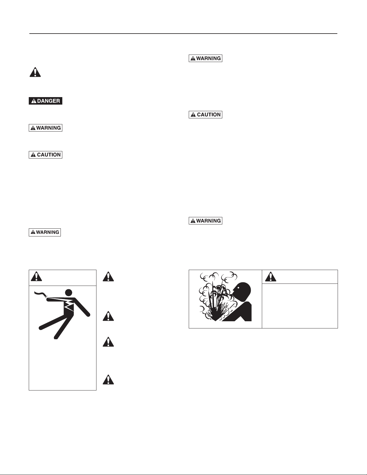
This is the safety alert symbol. When you see this
symbol on your pump or in this manual, look for
one of the following signal words and be alert to the
potential for personal injury:
warns about hazards that will cause seri-
ous personal injury, death or major property damage if
ignored.
ous personal injury, death or major property damage if
ignored.
minor personal injury or property damage if ignored.
The label NOTICE indicates special instructions which
are important but not related to hazards.
Carefully read and follow all safety instructions in this
manual and on pump.
Keep safety labels in good condition.
Replace missing or damaged safety labels.
California Proposition 65 Warning
tain chemicals known to the State of California to cause
cancer, birth defects or other reproductive harm.
warns about hazards that can cause seri-
warns about hazards that will or can cause
This product and related accessories con-
ELECTRICAL SAFETY
Capacitor voltage may be hazardous.
To discharge motor capacitor, hold insulated handle
screwdriver BY THE HANDLE and short capacitor terminals together. Do not touch metal screwdriver blade
or capacitor terminals. If in doubt, consult a qualified
electrician.
GENERAL SAFETY
Do not touch an operating motor. Modern
motors can operate at high temperatures. To avoid burns
when servicing pump, allow it to cool for 20 minutes
after shut-down before handling.
Do not allow pump or any system component to freeze.
To do so will void warranty.
Pump water only with this pump.
Periodically inspect pump and system components.
Wear safety glasses at all times when working on pumps.
Keep work area clean, uncluttered and properly lighted;
store properly all unused tools and equipment.
Keep visitors at a safe distance from the work areas.
Pump body may explode if used as a
booster pump unless relief valve capable of passing full
pump flow at 75 psi is installed.
WARNING
Hazardous voltage.
Can shock, burn, or
cause death.
Ground pump before
connecting to power
supply. Disconnect power
before working on pump,
motor or tank.
Wire motor for correct
voltage. See
“Electrical” section of
this manual and motor
nameplate.
Ground motor before
connecting to power
supply.
Meet National
Electrical Code,
Canadian Elec tri cal
Code, and local codes
for all wiring.
Follow wiring
instructions in this
manual when
connecting motor to
power lines.
WARNING
Hazardous pressure!
Install pressure relief
valve in discharge pipe.
Release all pressure on
system before working on
any component.

Table of Contents 3
Thank you for purchasing a top quality, factory tested pump.
Page
General Safety .....................................................................................................2
Warranty..............................................................................................................3
Installation ........................................................................................................4,5
Connecting Discharge Piping...............................................................................6
Electrical ...........................................................................................................7,8
Preparing To Start The Pump ...............................................................................9
Repair Parts .................................................................................................10-11
Troubleshooting ................................................................................................. 12
Limited Warranty
BERKELEY warrants to the original consumer purchaser (“Purchaser” or “You”) of the products listed below, that they will be free
from defects in material and workmanship for the Warranty Period shown below.
Product Warranty Period
Water Systems:
Water Systems Products — jet pumps, small centrifugal pumps, submersible pumps and
related accessories
Pro-Source™ Composite Tanks 5 years from date of original installation
Pro-Source™ Steel Pressure Tanks 5 years from date of original installation
Pro-Source™ Epoxy-Lined Tanks 3 years from date of original installation
Sump/Sewage/Effluent Products
Agricultural/Commercial:
Centrifugals – close-coupled motor drive, frame mount, SAE mount, engine drive, VMS, SSCX,
SSHM, solids handling, submersible solids handling
Submersible Turbines, 6” diameter and larger
Our limited warranty will not apply to any product that, in our sole judgement, has been subject to negligence, misapplication,
improper installation, or improper maintenance. Without limiting the foregoing, operating a three phase motor with single phase
power through a phase converter will void the warranty. Note also that three phase motors must be protected by three-leg,
ambient compensated, extra-quick trip overload relays of the recommended size or the warranty is void.
Your only remedy, and BERKELEY’s only duty, is that BERKELEY repair or replace defective products (at BERKELEY’s choice). You
must pay all labor and shipping charges associated with this warranty and must request warranty service through the installing
dealer as soon as a problem is discovered. No request for service will be accepted if received after the Warranty Period has
expired. This warranty is not transferable.
BERKELEY SHALL NOT BE LIABLE FOR ANY CONSEQUENTIAL, INCIDENTAL, OR CONTINGENT DAMAGES WHATSOEVER.
THE FOREGOING LIMITED WARRANTIES ARE EXCLUSIVE AND IN LIEU OF ALL OTHER EXPRESS AND IMPLIED WARRANTIES,
INCLUDING BUT NOT LIMITED TO IMPLIED WARRANTIES OF MERCHANTABILITY AND FITNESS FOR A PARTICULAR
PURPOSE. THE FOREGOING LIMITED WARRANTIES SHALL NOT EXTEND BEYOND THE DURATION PROVIDED HEREIN.
Some states do not allow the exclusion or limitation of incidental or consequential damages or limitations on the duration of an
implied warranty, so the above limitations or exclusions may not apply to You. This warranty gives You specific legal rights and You
may also have other rights which vary from state to state.
This Limited Warranty is effective June 1, 2011 and replaces all undated warranties and warranties dated before June 1, 2011.
whichever occurs first:
12 months from date of original installation, or
18 months from date of manufacture
12 months from date of original installation, or
18 months from date of manufacture
12 months from date of original installation, or
24 months from date of manufacture
12 months from date of original installation, or
24 months from date of manufacture
In the U.S.: BERKELEY, 293 Wright St., Delavan, WI 53115
In Canada: 269 Trillium Dr., Kitchener, Ontario N2G 4W5
Installation 4
To Household
Pump Priming
2347 0396
REPLACING AN OLD PUMP
Hazardous voltage. Disconnect power to
pump before working on pump or motor.
Step 1. Drain and remove the old pump. Check the old
pipe for scale, lime, rust, etc., and replace it if
necessary.
Step 2. Install the pump in the system. Make sure that all
pipe joints in the suction pipe are air-tight as well
as water tight. If the suction pipe can suck air, the
pump will not be able to pull water from the well.
Step 3. Adjust the pump mounting height so that the
plumbing connections do not put a strain on the
pump body. Support the pipe so that the pump
body does not take the weight of piping or fittings.
You have just completed the well plumbing for
your new shallow well jet pump. Please go to
Page 6 for discharge pipe and tank connections.
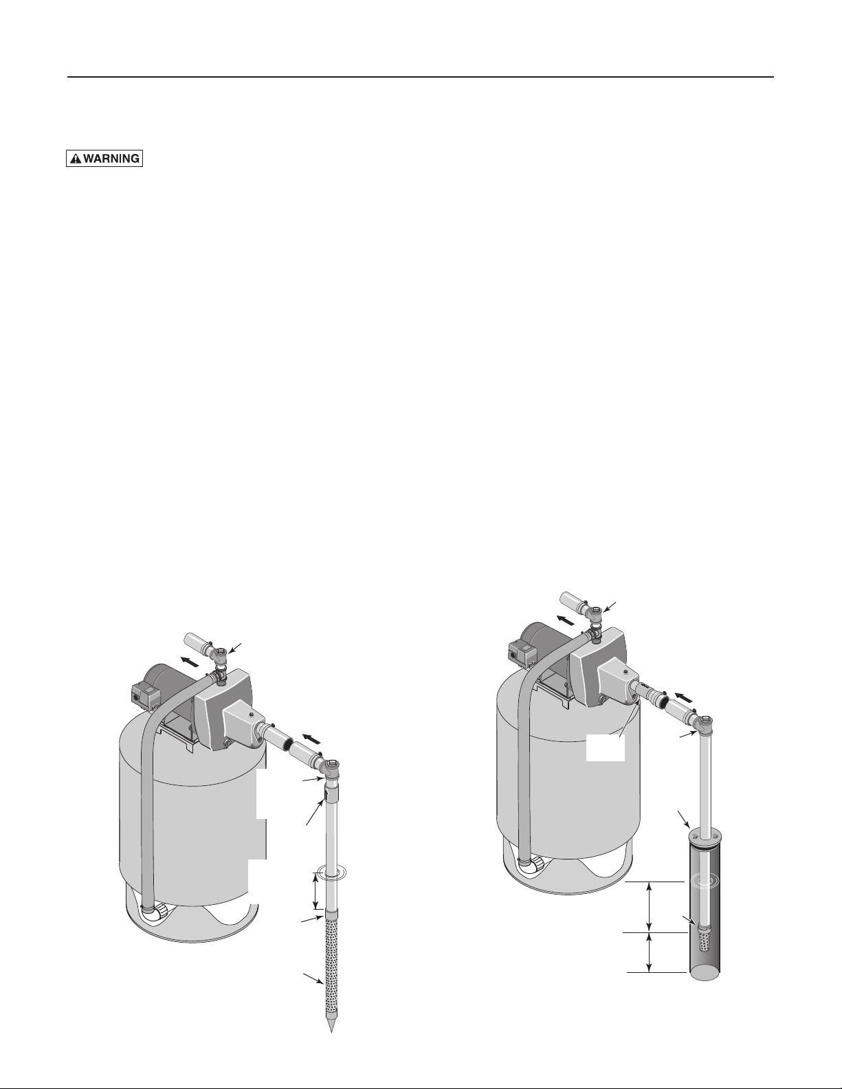
WELL POINT (DRIVEN POINT)
INSTALLATION (Figure 1)
Step 1. Drive the well, using “drive couplings” and a
“drive cap”. “Drive fittings” are threaded all the
way through and allow the pipe ends to butt
against each other so that the driving force of the
maul is carried by the pipe and not by the threads.
The ordinary fittings found in hardware stores are
not threaded all the way through the fitting and
can collapse under impact. “Drive fittings” are
also smoother than standard plumbing fittings,
making ground penetration easier.
To Household
Water System
Pump Priming
Tee and Plug
Suction Pipe
From Well
Priming
Tee and
Plug
Step 2. Mount the pump as close to the well as possible.
Step 3. Use the fewest possible fittings (especially
elbows) when connecting the pipe from the well
point to the pump suction port. The suction pipe
should be at least as large as the suction port on
the pump (include a check valve if your pump is
not equipped with one – see Figure 1). Support
the pipe so that there are no dips or sags in the
pipe, so it doesn’t strain the pump body, and
so that it slopes slightly upward from the well
to the pump (high spots can cause air pockets
which can air lock the pump). Seal the suction
pipe joints with PTFE pipe thread sealant tape.
Joints must be air- and water-tight. If the suction
pipe can suck air, the pump cannot pull water
from the well. If one well point does not supply
enough water, consider connecting two or three
well points to one suction pipe.
You have just completed the suction piping for
your new shallow well jet pump. Please go to
Page 6 for discharge pipe and tank connections.
CASED WELL INSTALLATION, 2” OR
LARGER CASING (Figure 2)
Step 1. Mount the pump as close to the well as possible.
Step 2. Assemble the foot valve, strainer, and well pipe
(see Figure 2). Make sure that the foot valve
works freely.
Water System
Check
Valve
Tee and Plug
Suction Pipe
From Well
Priming
Tee and
Plug
Sanitary
Well Seal
Drive point
below water
level
Not
to
Scale
Figure 1: Driven Point Installation
Check
Valve
Drive
Coupling
Drive
Point
Not
to
Scale
Figure 2: Cased Well Installation
5–10'
10'
Min.
Well
Casing
Foot
Valve
Installation 5
To Household
Pump Priming
Step 3. Lower the pipe into the well until the strainer is
five feet above the bottom of the well. It should
also be at least 10 feet below the well’s water level
while the pump is running in order to prevent the
pump from sucking air. Install a sanitary well seal.
Step 4. Install a priming tee, priming plug, and suction pipe
to the pump (see Figure 2). Connect the pipe from
the well to the pump suction port, using the fewest
possible fittings – especially elbows – as fittings
increase friction in the pipe (however, include a
foot valve – see Figure 2). The suction pipe should
be at least as large as the suction port on the pump.
Use PTFE pipe thread sealant tape on threaded pipe
joints. Support the pipe so that there are no dips
or sags in the pipe, so it doesn’t strain the pump
body, and so that it slopes slightly upward from the
well to the pump (high spots can cause air pockets
which can air lock the pump). Seal the suction pipe
joints with PTFE pipe thread sealant tape. Joints
must be air- and water-tight. If the suction pipe
can suck air, the pump cannot pull water from the
well.
You have just completed the suction piping for
your new shallow well jet pump. Please go to
Page 6 for discharge pipe and tank connections.
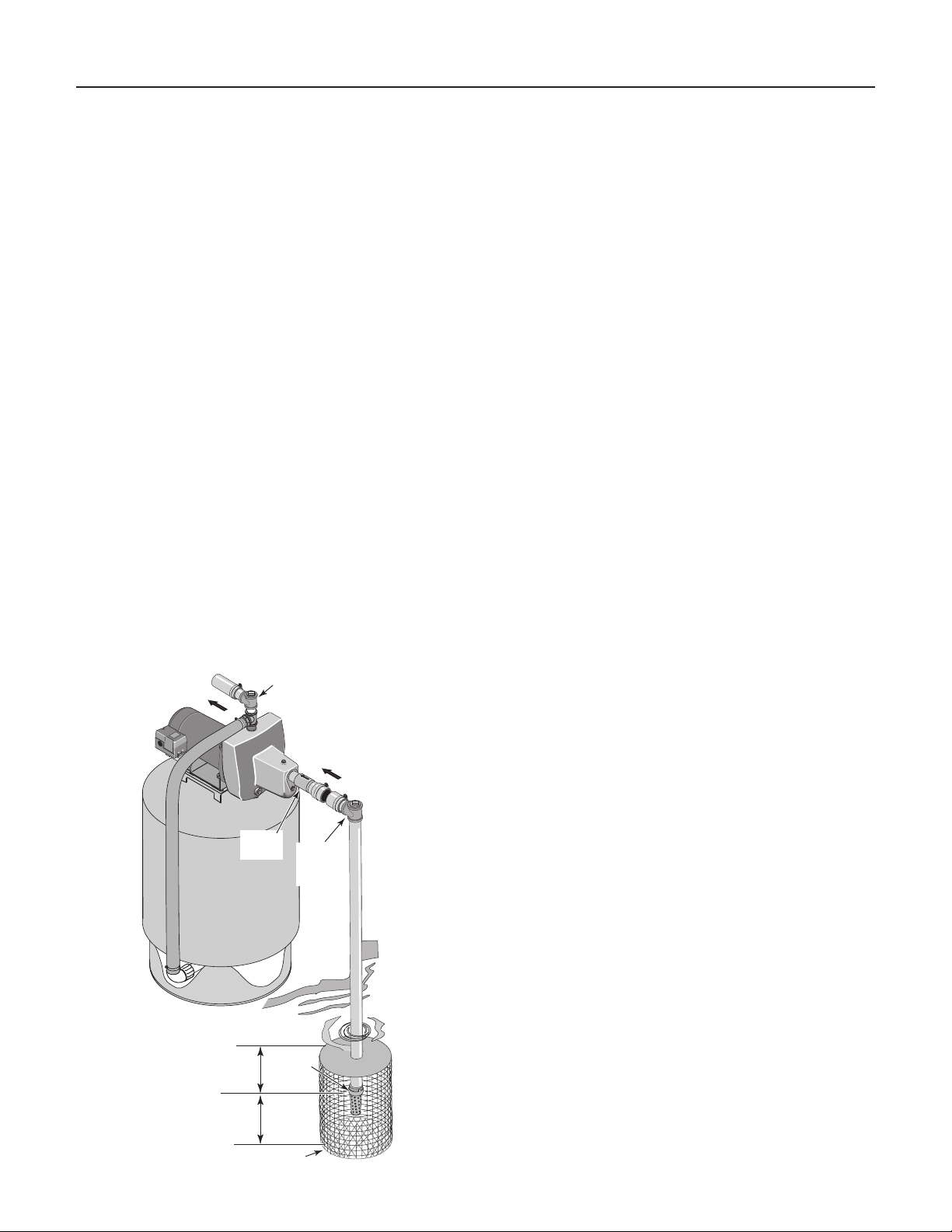
INSTALLATION FOR SURFACE WATER
(Figure 3)
Step 1. The pump should be installed as close to the
water as possible, with the fewest possible fittings
(especially elbows) in the suction pipe. The
suction pipe should be at least as large as the
suction port on the pump.
Step 2. Assemble a foot valve and suction pipe (see
Figure 3). Make sure that the foot valve works
freely. Use PTFE pipe thread sealant tape on
threaded pipe joints. Protect the foot valve
assembly from fish, trash, etc, by installing a
screen around it (see Figure 3).
Step 3. Lower the pipe into the water until the strainer
is five feet above the bottom. It should also be
at least 10 feet below the water level in order to
prevent the pump from sucking air.
Step 4. Install a priming tee, priming plug, and suction
pipe to the pump (see Figure 3). Support the pipe
so that there are no dips or sags in the pipe, so
it doesn’t strain the pump body, and so that it
slopes slightly upward from the well to the pump
(high spots can cause air pockets which can air
lock the pump). Seal the suction pipe joints with
PTFE pipe thread sealant tape. Joints must be airand water-tight. If the suction pipe can suck air,
the pump cannot pull water from the well.
You have just completed the plumbing for your
new shallow well jet pump. Please go to Page 6
for discharge pipe and tank connections.
Water System
Not
to
Scale
Check
Valve
10'
Min.
5–10'
Tee and Plug
Suction Pipe
From Well
Priming
Tee and
Plug
Foot
Valve
Screen
Figure 3: Surface Water Installation
Discharge Pipe and Pressure Tank Connections 6
To Household
Pump Priming
2349 0396
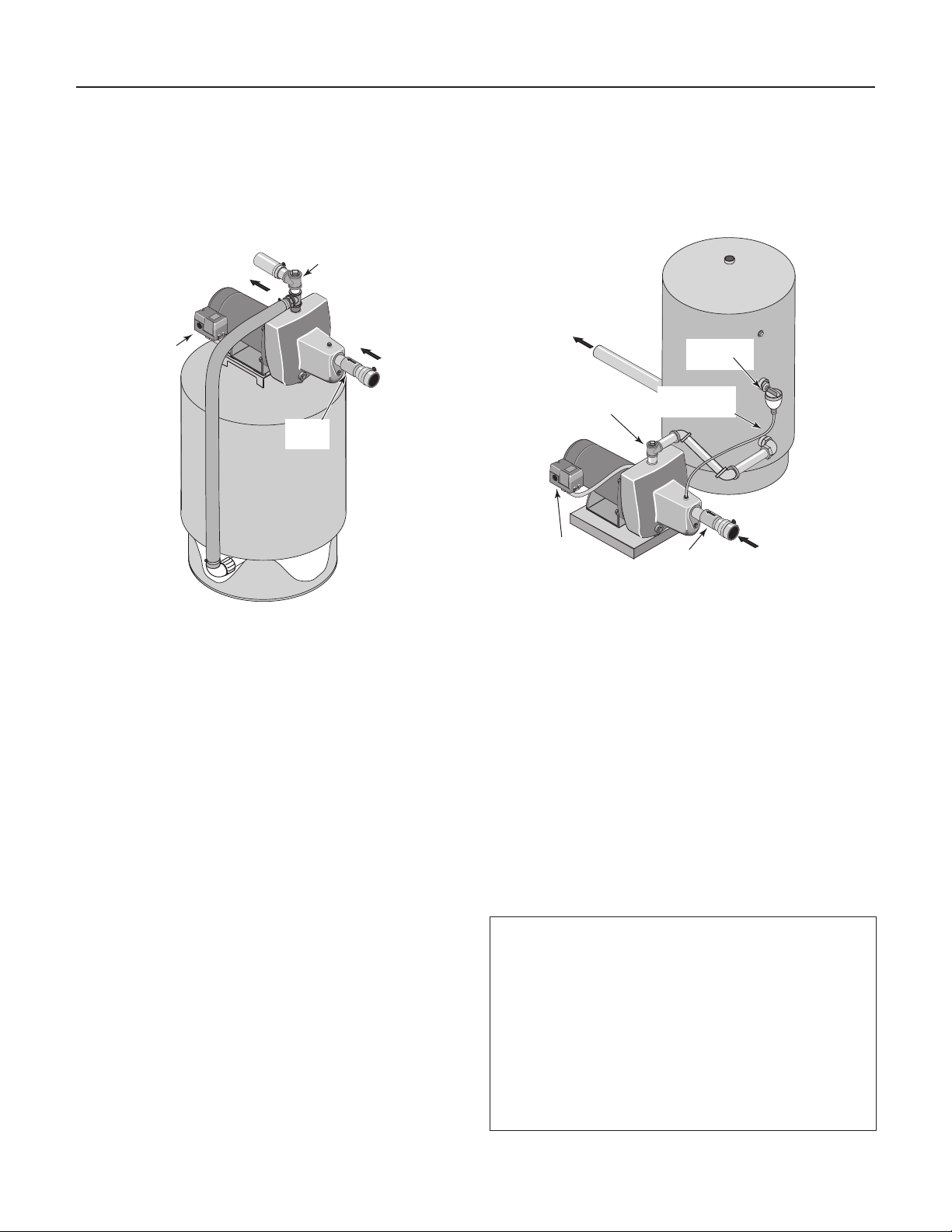
PRE-CHARGE TANK CONNECTION
(Figure 4)
Step 1. Install two tees in the pump discharge port (see
Figure 4). The pipe size must be at least as large
as the discharge port.
Water System
Pressure
Switch
Tee and Plug
From Well
Check
Valve
STANDARD TANK CONNECTION
(Figure 5)
Step 1. Install one tee in the pump discharge port (see
Figure 5).
To Household
Water System
Air Volume
Control
Pump
Priming Tee
and Plug
Pressure
Switch
Air Volume
Control Tube
From
Well
Check
Valve
Figure 4: Pre-charged Tank Connections
Step 2. Run a pipe or reinforced hose from one arm of
the first tee to the port on the pre-charged tank.
Step 3. Connect the other end of the discharge tee to
your plumbing system.
Step 4. Check the pre-charge of air in the tank with an
ordinary tire gauge. The pre-charge should be
2 PSI less than the cut-in setting of the pump’s
pressure switch. The pre-charge is measured
when there is no water pressure in the tank. Your
new pump has a 30/50 PSI switch, so adjust the
tank pre-charge pressure to 28 PSI.
Congratulations! You have just completed the
tank connection for your jet pump.
Please go to Pages 7 and 8 for electrical hookup.
Figure 5: Standard Tank Connections
Step 2. Run a pipe from the pump discharge port to the
inlet port of your tank. The pipe size must be at
least as large as the discharge port.
Step 3. Remove the 1/8” NPT pipe plug from the pump
Air Volume Control (AVC) port (see Figure 5).
Run tubing from the pump’s AVC port (see Figure
5) to the port on the AVC mounted on the tank.
See instructions provided with tank and AVC for
details. AVC port location will vary, depending on
your pump model (see exploded views, Page 10).
Congratulations! You have just completed the
tank connection for your jet pump.
Please go to Pages 7 and 8 for electrical hookup
Sealing Pipe Joints
Use only PTFE pipe thread sealant tape for making
all threaded connections to the pump itself. Do not
use pipe joint compounds on plastic pumps: they
can react with the plastic in pump components.
Make sure that all pipe joints in the suction pipe are
air tight as well as water tight. If the suction pipe
can suck air, the pump will not be able to pull water
from the well.
Electrical 7
3187 0704H
Disconnect power before working on pump, motor, pressure switch, or wiring.
MOTOR SWITCH SETTINGS
Dual-voltage motors (motors that can operate at either
115 or 230 volts), are set at the factory to 230 volts. Do
not change motor voltage setting if line voltage is 230
volts, or if you have a single voltage motor.
NOTE: Never wire a 115 volt motor to a 230 volt line.
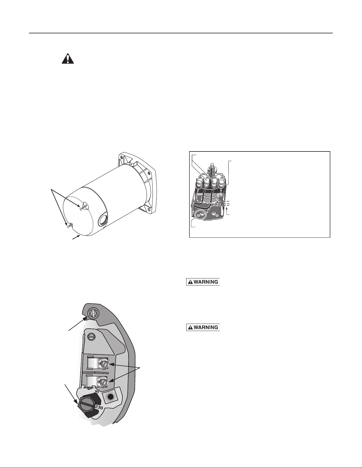
Remove Motor End Cover
If you have a dual-voltage motor, and will connect it to
115 volts, follow the procedure below.
End Cover Screws
Motor
End Cover
Figure 6: Removing Motor End Cover
To change to 115 volts:
Step 1. Make sure power is off.
Step 2. Turn the dial counter-clockwise until 115 shows
in the dial window.
Step 3. The wires from the pressure switch should
already be attached to to power lead terminals.
Step 4. Reinstall the Motor end cover.
Pressure Switch Wiring
Motor wires connect here.
Power supply wires connect here.
230 Volt: Connect 2 hot wires (black and red)
here and cap the white (neutral) wire. It does
not matter which wire goes to which screw.
115 Volt: Connect one hot wire (black or red)
to one of these screws (it doesn't matter
which one). Connect the white (neutral) wire
to the other screw. Cap any remaining
black or red wires.
Clamp the power cable to prevent strain
on the terminal screws.
Connect the green (or bare copper) ground wire
to the green ground screw.
Figure 8: Pressure Switch Wiring
You will need to remove the motor end cover to change
the voltage setting.
Your motor terminal board (located under the motor end
cover) should look like that shown below.
Ground
Screw
Power Lead
Voltage
Change Dial
Te rminals
Step 5. Go to Wiring Connections below.
Hazardous voltage. Can shock, burn, or
kill. Connect ground wire before connecting power
supply wires. Use the wire size (including the ground
wire) specified in the wiring chart. If possible, connect
the pump to a separate branch circuit with no other
appliances on it.
Explosion hazard. Do not ground to a gas
supply line.
Figure 7: Voltage set to 230 volts, Dial Type

Electrical 8
WIRING CONNECTIONS
Fire hazard. Incorrect voltage can cause
a fire or seriously damage the motor and voids the
warranty. The supply voltage must be within ±10% of
the motor nameplate voltage.
NOTICE: Dual-voltage motors are factory wired for 230
volts. If necessary, reconnect the motor for 115 volts, as
shown. Do not alter the wiring in single voltage motors.
Install, ground, wire, and maintain your pump in
compliance with the United States National Electrical
Code (NEC) or the Canadian Electrical Code (CEC), as
applicable, and with all local codes and ordinances that
apply. Consult your local building inspector for code
information.
Connection Procedure:
Step 1. Connect the ground wire first as shown in Figure
6. The ground wire must be a solid copper wire
at least as large as the power supply wires.
Step 2. There must be a solid metal connection between
the pressure switch and the motor for motor
grounding protection. If the pressure switch is
not connected to the motor, connect the green
ground screw in the switch to the green ground
screw under the motor end cover. Use a solid
copper wire at least as large as the power supply
wires.
Step 3. Connect the ground wire to a grounded lead in
a service panel, to a metal underground water
pipe, to a metal well casing at least ten feet (3M)
long, or to a ground electrode provided by the
power company or the hydro authority.
Step 4. Connect the power supply wires to the pressure
switch as shown in Figure 6.
You have just completed the wiring for your
pump.
Please go to Page 9 for startup preparations.
Wiring Chart – Recommended Wire and Fuse Sizes
Series HP Volts Amp Amp AWG WIRE SIZE (mm
5HN 1/2 115/230 12.2/6.1 20/15 12/14(3/2) 10/14(5.5/2) 8/14(8.4/2) 6/12(14/3) 6/12(14/3)
7HN 3/4 115/230 14.8/7.4 20/15 12/14(3/2) 8/14(8.4/2) 6/14(14/2) 6/12(14/3) 4/10(21/5.5)
10HN 1 115/230 19.2/9.6 25/15 10/14(5.5/2) 8/14(8.4/2) 6/12(14/3) 4/10(21/5.5) 4/10(21/5.5)
5SN 1/2 115/230 8.8/4.4 15/15 14/14(2/2) 12/14(3/2) 10/14(5.5/2) 8/14(8.4/2) 8/12(8.4/3)
7SN 3/4 115/230 12.2/6.1 20/15 12/14(3/2) 10/14(5.5/2) 8/14(8.4/2) 6/12(14/3) 6/12(14/3)
10SN 1 115/230 14.8/7.4 20/15 12/14(3/2) 8/14(8.4/2) 6/14(14/2) 6/12(14/3) 4/10(21/5.5)
15SN 1-1/2 115/230 19.2/9.6 25/15 10/14(5.5/2) 8/14(8.4/2) 6/14(14/2) 4/10(21/5.5) 4/10(21/5.5)
Motor
Max.
Load
DISTANCE IN FEET(METERS) FROM MOTOR TO SUPPLY
Branch
0 - 100 101 - 200 201 - 300 301 - 400 401 - 500
Fuse
(0 - 30) (31 - 61) (62 - 91) (92 - 122) (123 - 152)
Rating
2
)
 Loading...