

SIATA V132
SFE-EV VIRIDION
INSTALLER
MANUAL
WATER PURIFICATION

Installer Manual Siata V132-SFE-EV-VIRIDION - Table of contents
Table of contents
1. Generalities . . . . . . . . . . . . . . . . . . . . . . . . . . . . . . . . . . . . . . . . . . 7
1.1. Scope of the documentation . . . . . . . . . . . . . . . . . . . . . . . . . . . . . . . . 7
1.2. Release management . . . . . . . . . . . . . . . . . . . . . . . . . . . . . . . . . . . . . 7
1.3. Manufacturer identifier, product . . . . . . . . . . . . . . . . . . . . . . . . . . . .7
1.4. Intended use . . . . . . . . . . . . . . . . . . . . . . . . . . . . . . . . . . . . . . . . . . . . . 7
1.5. Abbreviations used . . . . . . . . . . . . . . . . . . . . . . . . . . . . . . . . . . . . . . . 8
1.6. Norms . . . . . . . . . . . . . . . . . . . . . . . . . . . . . . . . . . . . . . . . . . . . . . . . . . 8
1.6.1. Applicable norms . . . . . . . . . . . . . . . . . . . . . . . . . . . . . . . . . . . . . . . . . . . . 8
1.6.2. Available certificates . . . . . . . . . . . . . . . . . . . . . . . . . . . . . . . . . . . . . . . . . 8
1.7. Procedure for technical support . . . . . . . . . . . . . . . . . . . . . . . . . . . . 9
1.8. Copyright . . . . . . . . . . . . . . . . . . . . . . . . . . . . . . . . . . . . . . . . . . . . . . . 9
1.9. Limitation of liability . . . . . . . . . . . . . . . . . . . . . . . . . . . . . . . . . . . . . . 9
1.10. Scan & Service application . . . . . . . . . . . . . . . . . . . . . . . . . . . . . . . . 10
2. Safety . . . . . . . . . . . . . . . . . . . . . . . . . . . . . . . . . . . . . . . . . . . . . . 11
2.1. Safety pictograms definition . . . . . . . . . . . . . . . . . . . . . . . . . . . . . . . 11
2.2. Serial label location . . . . . . . . . . . . . . . . . . . . . . . . . . . . . . . . . . . . . . 11
2.3. Hazards . . . . . . . . . . . . . . . . . . . . . . . . . . . . . . . . . . . . . . . . . . . . . . . . 12
2.3.1. Personnel . . . . . . . . . . . . . . . . . . . . . . . . . . . . . . . . . . . . . . . . . . . . . . . . . 12
2.3.2. Material . . . . . . . . . . . . . . . . . . . . . . . . . . . . . . . . . . . . . . . . . . . . . . . . . . . 12
2.4. Hygiene and sanitization . . . . . . . . . . . . . . . . . . . . . . . . . . . . . . . . . . 13
2.4.1. Sanitary issues . . . . . . . . . . . . . . . . . . . . . . . . . . . . . . . . . . . . . . . . . . . . . 13
2.4.2. Hygiene measures . . . . . . . . . . . . . . . . . . . . . . . . . . . . . . . . . . . . . . . . . . 13
3. Description . . . . . . . . . . . . . . . . . . . . . . . . . . . . . . . . . . . . . . . . . 14
3.1. Valve versions . . . . . . . . . . . . . . . . . . . . . . . . . . . . . . . . . . . . . . . . . . 14
3.1.1. Twin pilots . . . . . . . . . . . . . . . . . . . . . . . . . . . . . . . . . . . . . . . . . . . . . . . . . 14
3.1.2. External connections . . . . . . . . . . . . . . . . . . . . . . . . . . . . . . . . . . . . . . . . 14
3.2. Technical specifications . . . . . . . . . . . . . . . . . . . . . . . . . . . . . . . . . . 15
3.2.1. Performance flow rate characteristics. . . . . . . . . . . . . . . . . . . . . . . . . . 16
3.3. Outline drawing . . . . . . . . . . . . . . . . . . . . . . . . . . . . . . . . . . . . . . . . . 17
3.4. Description and components location . . . . . . . . . . . . . . . . . . . . . . . 18
3.4.1. Valve with twin pilots . . . . . . . . . . . . . . . . . . . . . . . . . . . . . . . . . . . . . . . . 18
3.4.2. Valve with external pilots . . . . . . . . . . . . . . . . . . . . . . . . . . . . . . . . . . . . . 19
3.5. System regeneration cycle (5-cycle operation) . . . . . . . . . . . . . . . . 20
3.6. Options available on the valve . . . . . . . . . . . . . . . . . . . . . . . . . . . . . 23
2 / 110 Ref. MKT-IM-009 / C - 08.06.2018

Installer Manual Siata V132-SFE-EV-VIRIDION - Table of contents
4. System sizing . . . . . . . . . . . . . . . . . . . . . . . . . . . . . . . . . . . . . . . .26
4.1. Recommendations . . . . . . . . . . . . . . . . . . . . . . . . . . . . . . . . . . . . . . 26
4.1.1. Injector/DLFC/BLFC-Valve configuration . . . . . . . . . . . . . . . . . . . . . . . 26
4.2. Sizing a softener (single unit) . . . . . . . . . . . . . . . . . . . . . . . . . . . . . 26
4.2.1. Parameters to be considered. . . . . . . . . . . . . . . . . . . . . . . . . . . . . . . . . 26
4.2.2. Determining the required volume of resin . . . . . . . . . . . . . . . . . . . . . . 28
4.2.3. Resin exchange capacity and capacity of the unit . . . . . . . . . . . . . . . . 29
4.2.4. Valve configuration . . . . . . . . . . . . . . . . . . . . . . . . . . . . . . . . . . . . . . . . . 31
4.2.5. Cycle time calculation. . . . . . . . . . . . . . . . . . . . . . . . . . . . . . . . . . . . . . . 32
4.2.6. Brine refill - cycle . . . . . . . . . . . . . . . . . . . . . . . . . . . . . . . . . . . . . . . . . . 33
4.3. Salt amount definition . . . . . . . . . . . . . . . . . . . . . . . . . . . . . . . . . . . 33
4.4. Injector flow rates (tables) . . . . . . . . . . . . . . . . . . . . . . . . . . . . . . . . 34
5. Installation . . . . . . . . . . . . . . . . . . . . . . . . . . . . . . . . . . . . . . . . . .35
5.1. Warnings . . . . . . . . . . . . . . . . . . . . . . . . . . . . . . . . . . . . . . . . . . . . . . 35
5.2. Safety notices for installation . . . . . . . . . . . . . . . . . . . . . . . . . . . . . 35
5.3. Installation environment . . . . . . . . . . . . . . . . . . . . . . . . . . . . . . . . . 35
5.3.1. Tips and suggestions . . . . . . . . . . . . . . . . . . . . . . . . . . . . . . . . . . . . . . . 35
5.3.2. General. . . . . . . . . . . . . . . . . . . . . . . . . . . . . . . . . . . . . . . . . . . . . . . . . . . 37
5.3.3. Water . . . . . . . . . . . . . . . . . . . . . . . . . . . . . . . . . . . . . . . . . . . . . . . . . . . . 37
5.3.4. Electrical . . . . . . . . . . . . . . . . . . . . . . . . . . . . . . . . . . . . . . . . . . . . . . . . . 37
5.3.5. Mechanical. . . . . . . . . . . . . . . . . . . . . . . . . . . . . . . . . . . . . . . . . . . . . . . . 38
5.3.6. Integration constraints . . . . . . . . . . . . . . . . . . . . . . . . . . . . . . . . . . . . . . 38
5.4. Block diagram and configuration example . . . . . . . . . . . . . . . . . . 39
5.5. Valve connection to piping . . . . . . . . . . . . . . . . . . . . . . . . . . . . . . . . 40
5.5.1. Top-mounted valve installation . . . . . . . . . . . . . . . . . . . . . . . . . . . . . . . 40
5.6. Electrical connections . . . . . . . . . . . . . . . . . . . . . . . . . . . . . . . . . . . 42
5.7. Bypassing . . . . . . . . . . . . . . . . . . . . . . . . . . . . . . . . . . . . . . . . . . . . . 43
5.7.1. Manual Bypass . . . . . . . . . . . . . . . . . . . . . . . . . . . . . . . . . . . . . . . . . . . . 43
5.7.2. Automatic Bypass . . . . . . . . . . . . . . . . . . . . . . . . . . . . . . . . . . . . . . . . . . 44
5.8. Drain line connection . . . . . . . . . . . . . . . . . . . . . . . . . . . . . . . . . . . . 45
5.9. Overflow line connection . . . . . . . . . . . . . . . . . . . . . . . . . . . . . . . . . 46
5.10. Brine line connection . . . . . . . . . . . . . . . . . . . . . . . . . . . . . . . . . . . . 46
5.11. Chlorinator . . . . . . . . . . . . . . . . . . . . . . . . . . . . . . . . . . . . . . . . . . . . 46
Ref. MKT-IM-009 / C - 08.06.2018 3 / 110

Installer Manual Siata V132-SFE-EV-VIRIDION - Table of contents
6. Programming . . . . . . . . . . . . . . . . . . . . . . . . . . . . . . . . . . . . . . . 47
6.1. General information . . . . . . . . . . . . . . . . . . . . . . . . . . . . . . . . . . . . . 47
6.2. Display . . . . . . . . . . . . . . . . . . . . . . . . . . . . . . . . . . . . . . . . . . . . . . . . 48
6.3. Password . . . . . . . . . . . . . . . . . . . . . . . . . . . . . . . . . . . . . . . . . . . . . . 49
6.4. Controller setting . . . . . . . . . . . . . . . . . . . . . . . . . . . . . . . . . . . . . . . . 49
6.4.1. Basic programming . . . . . . . . . . . . . . . . . . . . . . . . . . . . . . . . . . . . . . . . . 50
6.4.2. Intermediate programming . . . . . . . . . . . . . . . . . . . . . . . . . . . . . . . . . . . 51
6.4.3. Advanced programming . . . . . . . . . . . . . . . . . . . . . . . . . . . . . . . . . . . . . . 61
6.5. Statistics . . . . . . . . . . . . . . . . . . . . . . . . . . . . . . . . . . . . . . . . . . . . . . . 65
6.5.1. Resetting the statistics. . . . . . . . . . . . . . . . . . . . . . . . . . . . . . . . . . . . . . . 66
6.6. Resetting the controller . . . . . . . . . . . . . . . . . . . . . . . . . . . . . . . . . . 67
6.6.1. Resetting the EEPROM . . . . . . . . . . . . . . . . . . . . . . . . . . . . . . . . . . . . . . . 67
6.6.2. Resetting the hardware . . . . . . . . . . . . . . . . . . . . . . . . . . . . . . . . . . . . . . 67
7. Commissioning . . . . . . . . . . . . . . . . . . . . . . . . . . . . . . . . . . . . . . 68
7.1. Start up procedure . . . . . . . . . . . . . . . . . . . . . . . . . . . . . . . . . . . . . . 68
7.2. Sanitization . . . . . . . . . . . . . . . . . . . . . . . . . . . . . . . . . . . . . . . . . . . . . 69
7.2.1. Disinfection of water softeners . . . . . . . . . . . . . . . . . . . . . . . . . . . . . . . . 69
7.2.2. Sodium or calcium hypochlorite . . . . . . . . . . . . . . . . . . . . . . . . . . . . . . . 69
8. Operation . . . . . . . . . . . . . . . . . . . . . . . . . . . . . . . . . . . . . . . . . . . 70
8.1. Display examples . . . . . . . . . . . . . . . . . . . . . . . . . . . . . . . . . . . . . . . . 70
8.2. Recommendations . . . . . . . . . . . . . . . . . . . . . . . . . . . . . . . . . . . . . . . 71
8.3. Manual regeneration . . . . . . . . . . . . . . . . . . . . . . . . . . . . . . . . . . . . . 71
8.4. Cancelling a regeneration . . . . . . . . . . . . . . . . . . . . . . . . . . . . . . . . . 71
8.5. Regeneration with remote start signal and regeneration inhibit
signal . . . . . . . . . . . . . . . . . . . . . . . . . . . . . . . . . . . . . . . . . . . . . . . . . 71
8.6. Holiday function . . . . . . . . . . . . . . . . . . . . . . . . . . . . . . . . . . . . . . . . . 72
8.7. Battery operation . . . . . . . . . . . . . . . . . . . . . . . . . . . . . . . . . . . . . . . . 72
8.8. Service position search . . . . . . . . . . . . . . . . . . . . . . . . . . . . . . . . . . . 72
8.9. Salt Alarm function . . . . . . . . . . . . . . . . . . . . . . . . . . . . . . . . . . . . . . 72
8.10. Operation during a power failure . . . . . . . . . . . . . . . . . . . . . . . . . . .73
8.11. Other Key Functions . . . . . . . . . . . . . . . . . . . . . . . . . . . . . . . . . . . . . 73
4 / 110 Ref. MKT-IM-009 / C - 08.06.2018

Installer Manual Siata V132-SFE-EV-VIRIDION - Table of contents
9. Maintenance . . . . . . . . . . . . . . . . . . . . . . . . . . . . . . . . . . . . . . . . .74
9.1. Recommendations . . . . . . . . . . . . . . . . . . . . . . . . . . . . . . . . . . . . . . 74
9.1.1. Use original spare parts . . . . . . . . . . . . . . . . . . . . . . . . . . . . . . . . . . . . . 74
9.1.2. Use original approved lubricants. . . . . . . . . . . . . . . . . . . . . . . . . . . . . . 74
9.1.3. Maintenance instructions . . . . . . . . . . . . . . . . . . . . . . . . . . . . . . . . . . . . 74
9.2. Cleaning and maintenance . . . . . . . . . . . . . . . . . . . . . . . . . . . . . . . 74
9.2.1. First steps . . . . . . . . . . . . . . . . . . . . . . . . . . . . . . . . . . . . . . . . . . . . . . . . 74
9.2.2. Controller battery replacement . . . . . . . . . . . . . . . . . . . . . . . . . . . . . . . 75
9.2.3. Controller on valve installation . . . . . . . . . . . . . . . . . . . . . . . . . . . . . . . 76
9.2.4. Motor replacement . . . . . . . . . . . . . . . . . . . . . . . . . . . . . . . . . . . . . . . . . 78
9.2.5. Micro-switch replacement . . . . . . . . . . . . . . . . . . . . . . . . . . . . . . . . . . . 78
9.2.6. Brine valve replacement. . . . . . . . . . . . . . . . . . . . . . . . . . . . . . . . . . . . . 80
9.2.7. Injector and injector screen cleaning . . . . . . . . . . . . . . . . . . . . . . . . . . 82
9.2.8. Twin pilots replacement . . . . . . . . . . . . . . . . . . . . . . . . . . . . . . . . . . . . . 84
9.2.9. Pilots (external drivers connections) replacement . . . . . . . . . . . . . . . 86
9.2.10. Internal pistons & seals and spacers replacement . . . . . . . . . . . . . . . 88
9.2.11. Drain connection replacement. . . . . . . . . . . . . . . . . . . . . . . . . . . . . . . . 92
9.2.12. Valve on tank assembly . . . . . . . . . . . . . . . . . . . . . . . . . . . . . . . . . . . . . 93
10. Troubleshooting . . . . . . . . . . . . . . . . . . . . . . . . . . . . . . . . . . . . . .94
10.1. Alarm messages . . . . . . . . . . . . . . . . . . . . . . . . . . . . . . . . . . . . . . . . 98
11. Spare parts . . . . . . . . . . . . . . . . . . . . . . . . . . . . . . . . . . . . . . . . .100
11.1. Valve parts list . . . . . . . . . . . . . . . . . . . . . . . . . . . . . . . . . . . . . . . . 100
11.2. SFE-EV-VIRIDION spare parts . . . . . . . . . . . . . . . . . . . . . . . . . . . . 104
11.3. Fittings . . . . . . . . . . . . . . . . . . . . . . . . . . . . . . . . . . . . . . . . . . . . . . . 106
11.4. Accessories . . . . . . . . . . . . . . . . . . . . . . . . . . . . . . . . . . . . . . . . . . . 107
12. Disposal . . . . . . . . . . . . . . . . . . . . . . . . . . . . . . . . . . . . . . . . . . . .109
Ref. MKT-IM-009 / C - 08.06.2018 5 / 110

Installer Manual Siata V132-SFE-EV-VIRIDION - Table of contents
PAGE INTENTIONALLY LEFT BLANK
6 / 110 Ref. MKT-IM-009 / C - 08.06.2018
Installer Manual Siata V132-SFE-EV-VIRIDION - Generalities
1. Generalities
1.1. Scope of the documentation
The documentation provides the necessary information for appropriate use of the product. It informs
the user to ensure efficient execution of the installation, operation or maintenance procedures.
The content of this document is based on the information available at the time of publication. The
original version of the document was written in English.
For safety and environmental protection reasons, the safety instructions given in this documentation
must be strictly followed.
This manual is a reference and will not include every system installation situation. The person
installing this equipment should have:
• training in the Siata series, SFE-EV-VIRIDION controllers and water softener installation;
• knowledge of water conditioning and how to determine proper controller settings;
• basic plumbing skills.
This document is available in other languages on www.pentairaquaeurope.com/product-finder/
product-type/control-valves.
1.2. Release management
Revision Date Authors Description
A 21.12.2016 BRY/GPI First edition.
B 22.02.2018 BRY/DSP Revision of chapter 6 Programming.
C 08.06.2018 BRY/FIM
Address change, Bleam information and valve on
tank assembly.
1.3. Manufacturer identifier, product
Manufacturer: Pentair International LLC
Avenue de Sevelin 18
1004 Lausanne
Switzerland
Product: Siata V132-SFE-EV-VIRIDION
1.4. Intended use
The device is intended for residential, commercial or light industry environment (ref. EN 50081-1) use
only and it is purpose-built for treatment and softening of water coming from supply network.
Ref. MKT-IM-009 / C - 08.06.2018 7 / 110

Installer Manual Siata V132-SFE-EV-VIRIDION - Generalities
1.5. Abbreviations used
Assy......................................................... Assembly
BLFC ....................................................... Brine Line Flow Controller
BV............................................................ Brine Valve
DF............................................................ Down Flow
DLFC ....................................................... Drain Line Flow Controller
Inj ............................................................ Injector
QC............................................................ Quick Connect
Regen...................................................... Regeneration
S&S ......................................................... Seals & Spacers
SBV.......................................................... Safety Brine Valve
TC ............................................................ Time Clock
1.6. Norms
1.6.1. Applicable norms
Comply with the following guidelines:
• 2006/42/EC: Machinery Directive;
• 2014/35/UE: Low Voltage Directive;
• 2014/30/UE: Electromagnetic compatibility;
• UNI EN ISO 9001 (Certificate no. 95.022 SSG ICS).
Meets the following technical standards:
• EN 61010-1;
• EN 61000-6-1;
• EN 61000-6-2;
• EN 61000-6-3;
• EN 61000-6-4;
• EN 55014-1;
• EN 55014-2.
1.6.2. Available certificates
•CE;
•DM174;
•ACS.
8 / 110 Ref. MKT-IM-009 / C - 08.06.2018
Access to all certifications:

Installer Manual Siata V132-SFE-EV-VIRIDION - Generalities
1.7. Procedure for technical support
Procedure to follow for any technical support request:
A Collect the required information for a technical assistance request.
→ Product identification (see 2.2. Serial label location, page 11 and 9.1. Recommendations,
page 74);
→ Problem description of the device.
B Please refer to the "Troubleshooting" chapter, page 94. If the problem persists contact your
supplier.
1.8. Copyright
© 2018 Pentair International Sàrl All rights reserved.
1.9. Limitation of liability
Pentair Quality System EMEA products benefit, under specific conditions, from a manufacturer
warranty that may be invoked by Pentair’s direct customers. Users should contact the vendor of this
product for applicable conditions and in case of a potential warranty claim.
Any warranty provided by Pentair regarding the product will become invalid in case of:
• improper installation, improper programming, improper use, improper operation and/or
maintenance leading to any kind of product damages;
• improper or unauthorized intervention on the controller or components;
• incorrect, improper or wrong connection/assembly of systems or products with this product and
vice versa;
• use of a non-compatible lubricant, grease or chemicals of any type and not listed by the
manufacturer as compatible for the product;
• failure due to wrong configuration and/or sizing.
Pentair accepts no liability for equipment installed by the user upstream or downstream of Pentair
products, as well as for process/production processes which are installed and connected around or
even related to the installation. Disturbances, failures, direct or indirect damages that are caused by
such equipment or processes are also excluded from the warranty. Pentair shall not accept any
liability for any loss or damage of profits, revenues, use, production, or contracts, or for any indirect,
special or consequential loss or damage whatsoever. Please refer to the Pentair List Price to know
more about terms and conditions applicable to this product.
Ref. MKT-IM-009 / C - 08.06.2018 9 / 110
Installer Manual Siata V132-SFE-EV-VIRIDION - Generalities
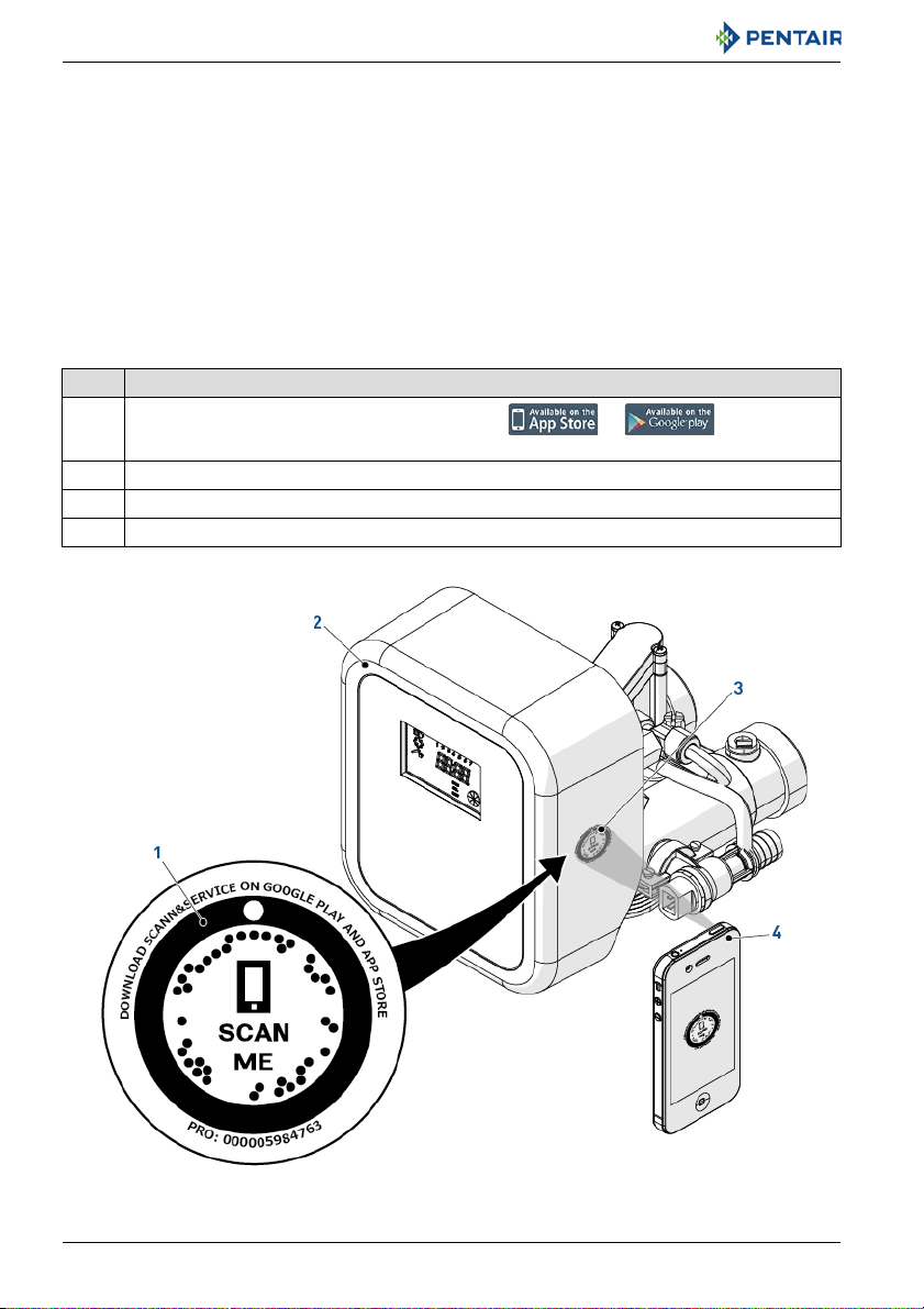
1.10. Scan & Service application
Scan & Service mobile application is the ideal support for the maintenance person in his daily
business. A simple scan of an identification (ID) label (1) present on the valve with a smartphone gives
an instantaneously access to all updated information related to the product, such as:
• valve’s and tanks detailed configuration;
•manuals;
• spare parts lists;
• troubleshooting recommendations;
• multi-lingual videos, detailing how to best service a part;
• informations about new products, latest technologies, novelties about the Blue Network
program, etc....
No. Operation
Download the application "Scan & Service" from or in a
A
smartphone (4).
B Open the application "Scan & Service".
C Scan the bleam (3) stuck on the valve (2).
D Navigate to find information.
10 / 110 Ref. MKT-IM-009 / C - 08.06.2018
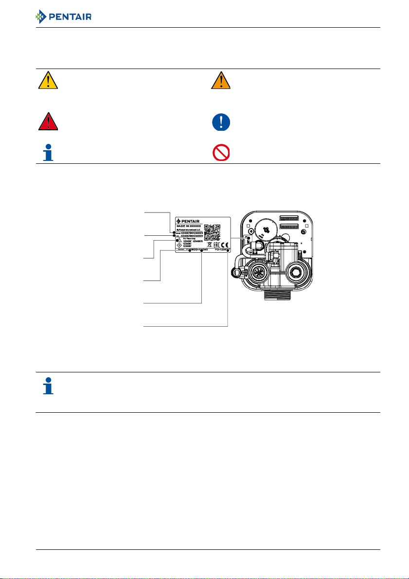
2. Safety
Model
Electrical rating
Part number
Production date
Production order
Serial number
2.1. Safety pictograms definition
Caution
Warns of a risk of minor injury or major
material damage to the device or
environment.
Danger
Warns against serious personal injury or
death.
Note
Comment.
2.2. Serial label location
Installer Manual Siata V132-SFE-EV-VIRIDION - Safety
Warning
Warns against serious personal injury
and damage to health.
Mandatory
Standard or measure to apply.
Prohibition
Restriction to be observed.
Note
Ensure that the serial label and the safety tags on the device are completely legible and
clean. If necessary, replace them with new tags and put them in the same places.
Ref. MKT-IM-009 / C - 08.06.2018 11 / 110

Installer Manual Siata V132-SFE-EV-VIRIDION - Safety
2.3. Hazards
All the safety and protection instructions contained in this document must be observed in order to
avoid temporary or permanent injury, damage to property or environmental pollution.
At the same time, any other legal regulations, accident prevention and environmental protection
measures, as well as any recognized technical regulations relating to appropriate and risk-free
methods of working which apply in the country and place of use of the device must be adhered to.
Any non-observation of the safety and protection rules, as well as any existing legal and technical
regulations, will result in a risk of temporary or permanent injury, damage to property or
environmental pollution.
2.3.1. Personnel
Only qualified and professional personnel, based on their training, experience and instruction as well
as their knowledge of the regulations, the safety rules and operations performed, are authorized to
carry out necessary work.
The device must not be used by children aged under 8 years old or people with reduced physical,
sensory or mental capabilities.
People with a lack of experience or without the necessary knowledge should not use the device.
Do not allow children to play with the device. Cleaning and maintenance intended to be performed by
the user must not be performed by unsupervised children.
2.3.2. Material
The following points must be observed to ensure proper operation of the system and the safety of
users:
• beware of high voltages present on the transformer (230V);
• do not put your fingers in the system (risk of injuries with moving parts and shock due to electric
voltage).
12 / 110 Ref. MKT-IM-009 / C - 08.06.2018
Installer Manual Siata V132-SFE-EV-VIRIDION - Safety
2.4. Hygiene and sanitization
2.4.1. Sanitary issues
Preliminary checks and storage
• Check the integrity of the packaging. Check that there is no damage and no signs of contact with
liquid to make sure that no external contamination occurred;
• the packaging has a protective function and must be removed just before installation. For
transportation and storage appropriate measures should be adopted to prevent the
contamination of materials or objects themselves.
Assembly
• Assemble only with components which are in accordance with drinking water standards;
• after installation and before use, perform one or more manual regenerations in order to clean
the media bed. During such operations, do not use the water for human consumption. Perform a
disinfection of the system in the case of installations for treatment of drinking water for human
use.
Note
This operation must be repeated in the case of ordinary and extraordinary maintenance. It
should also be repeated whenever the system remains idle for a significant time.
Note
Valid only for Italy
signs and obligations arising from the DM25.
: In case of equipment used in accordance with the DM25, apply all the
2.4.2. Hygiene measures
Disinfection
• The materials used for the construction of our products meet the standards for use with potable
water; the manufacturing processes are also geared to preserving these criteria. However, the
process of production, distribution, assembly and installation, may create conditions of bacterial
proliferation, which may lead to odor problems and water contamination;
• it is therefore strongly recommended to sanitize the products. See 7.2. Sanitization, page 69;
• maximum cleanliness is recommended during the assembly and installation;
• for disinfection, use sodium or calcium hypochlorite and perform a manual regeneration.
Ref. MKT-IM-009 / C - 08.06.2018 13 / 110
Installer Manual Siata V132-SFE-EV-VIRIDION - Description
External connections Twin pilots
3. Description
3.1. Valve versions
3.1.1. Twin pilots
The pressure distributor pilot is mounted directly on top of the V132, in this case inlet water is the
control fluid and feeds the pilot circuit from the top collector. A controller with a proper camshaft
(called twin pilot camshaft) must be mounted on top of the valve and linked to the pilot stems. The
rotation of the camshaft moves the stems of the pilots in/out the pilot circuit, deviating the control
water inside the proper side of the V132 pressure chambers to move the pistons of the valve according
to the various cycles/phases.
3.1.2. External connections
There are four quick connection ports on top of the valve, each port is linked to a pressure chamber
inside the valve. The hydraulic distributor with pilots has to be mounted remotely from the valve, the
pilot ports can be connected to valve ports with a diameter of 6 mm flexible tubing.
The remote camshaft can control up to 4 pilots hence more valves can be controlled with a single
distributor. For this reason this configuration is generally used to:
• add outlet shut off pneumatic valve;
• add bypass during regeneration;
• control a valve in the suction line and make a timed brine draw.
14 / 110 Ref. MKT-IM-009 / C - 08.06.2018

Installer Manual Siata V132-SFE-EV-VIRIDION - Description
3.2. Technical specifications
Design specifications/ratings
Valve body ...............................................Glassfiber reinforced ABS
Rubber components ............................... NBR
Valve material certification .................... DM174, ACS, W270
Weight (valve with controller)................. 2.5 kg (max.)
Recommended operating pressure ....... 1.5 - 6 bar
Hydrostatic test pressure....................... 22 bar
Water temperature................................. 5 - 40°C
Ambient temperature ............................. 5 - 40°C
Maximum relative humidity .................... 80% for temperatures up to 31 °C decreasing linearly to 50%
relative humidity at 40°C;
Indoor use only
Flow rates (3.5 bar inlet - valve only)
Continuous (Δp = 1 bar) .......................... 7.0 m
Cv*........................................................... 8.09 gpm
Kv*........................................................... 7 m
Maximum backwash (Δp = 1.8 bar) ........ 3.0 m
*Cv: Flow rate in gpm across the valve at a pressure drop of 1 psi at 60°F.
*Kv: Flow rate in m
3
/h across the valve at a pressure drop of 1 bar at 16°C.
3
/h
3
/h
3
/h
Valve connections
Tank thread............................................. 2 ½" 8 NPSM
Inlet/outlet ..............................................Male 2" BSP or various QC fittings
Riser tube ............................................... 32 mm
Drain line ................................................ 20 mm
Brine line ................................................ ⅜"
Electrical
Controller................................................ 12 VAC, 50/60 Hz, 4 W, Class III
Input supply frequency ...........................50 or 60 Hz (controller configuration dependent)
Transformer*.......................................... 230 VAC, 50/60 Hz, 11.5 VA, Class II
Motor input voltage................................. 12 VAC
Chlorine producer input ......................... 6 VDC, 800 mA
Protection rating..................................... IP 40
*: The device must only be used with the transformer provided in order to guarantee the safety voltage supply.
Ref. MKT-IM-009 / C - 08.06.2018 15 / 110
Installer Manual Siata V132-SFE-EV-VIRIDION - Description
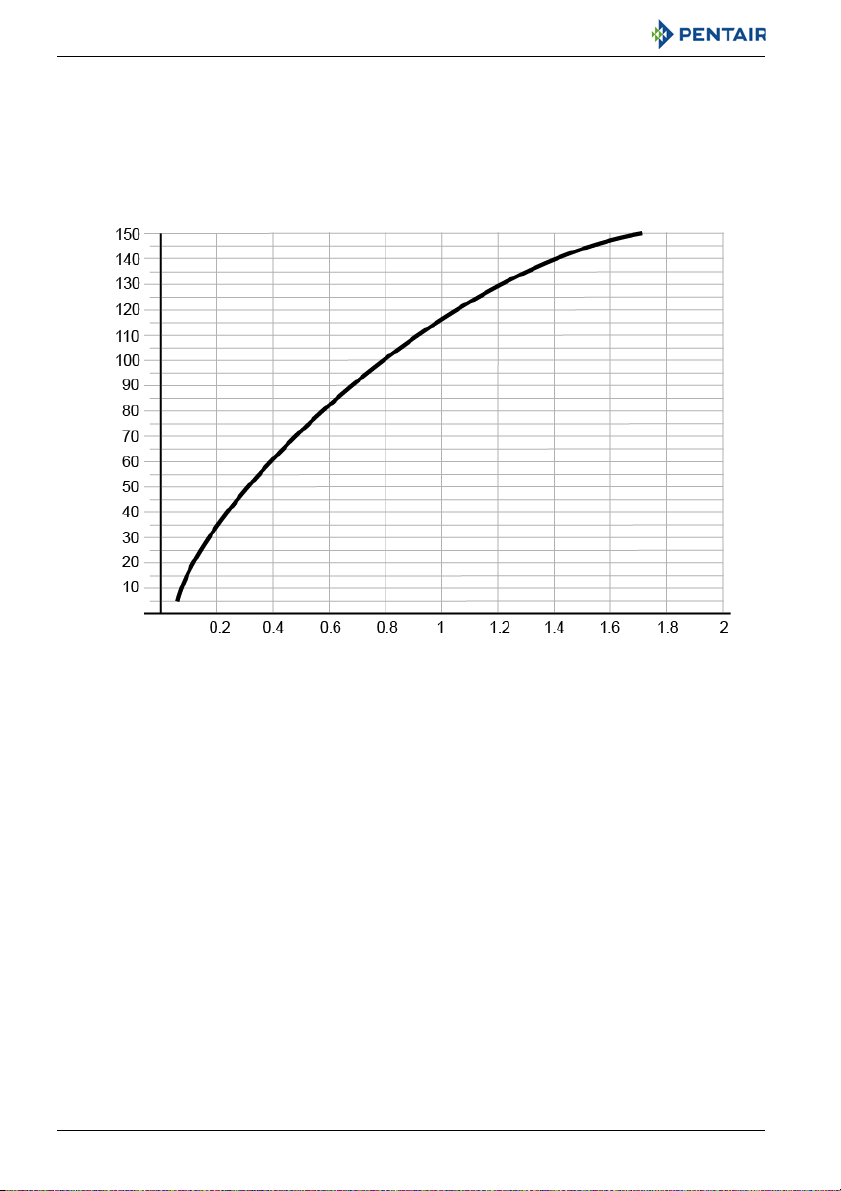
FLOW RATE VS PRESSURE DROP
Flow rate (L/min]
Pressure drop (bar)
3.2.1. Performance flow rate characteristics
The graph shows the pressure drop created by the valve itself at different flow rates. It makes it
possible to predetermine the maximum flow rate going through the valve depending on the system
settings (inlet pressure etc). It also makes it possible to determine the valve pressure drop at a given
flow rate, and therefore to evaluate the system pressure drop vs flow rate.
16 / 110 Ref. MKT-IM-009 / C - 08.06.2018
3.3. Outline drawing
Installer Manual Siata V132-SFE-EV-VIRIDION - Description
Ref. MKT-IM-009 / C - 08.06.2018 17 / 110
Installer Manual Siata V132-SFE-EV-VIRIDION - Description
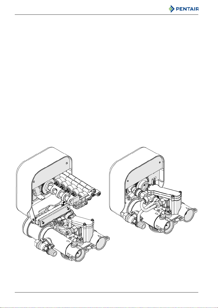
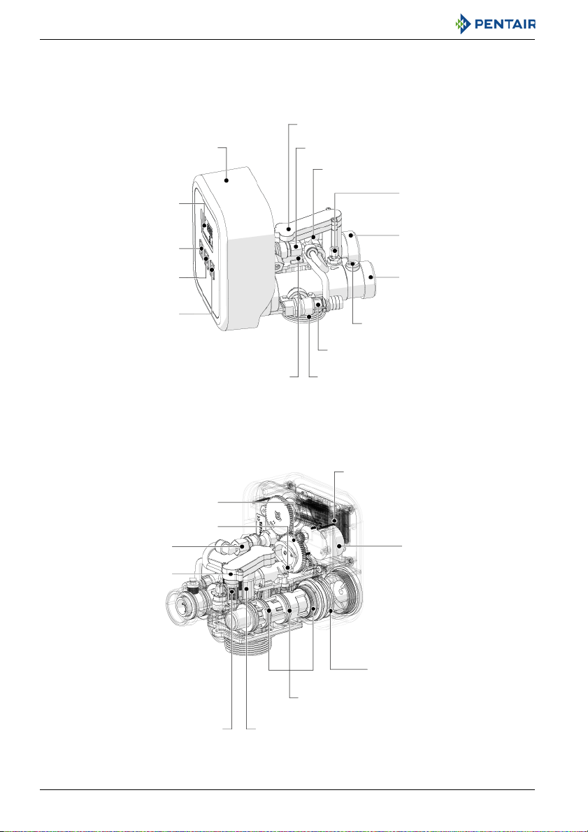
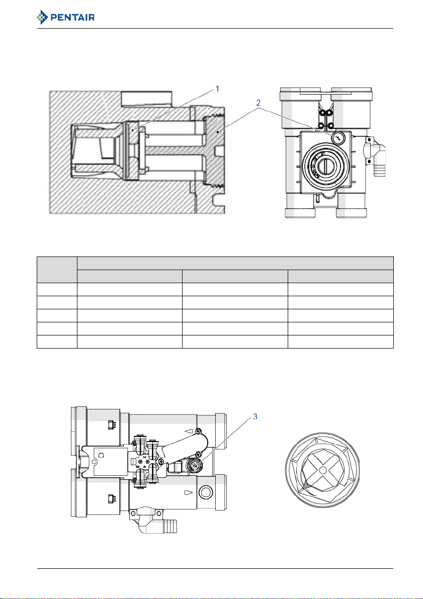
SFE-EV-VIRIDION Controller
LCD Display
Down button
Up button
Regen button
Long manifold
Brine Valve
Injector
Inlet
Mixing device
Outlet + turbine
Volumetric sensor input
Drain line connection
Tank connection
Twin pilots
Camshaft
Pilots
Injector screen
Injector
Seals and spacer with NUT
Inlet/Outlet pistons
Motor
Electronic board with reset button
Long manifold
Brine valve
3.4. Description and components location
3.4.1. Valve with twin pilots
18 / 110 Ref. MKT-IM-009 / C - 08.06.2018
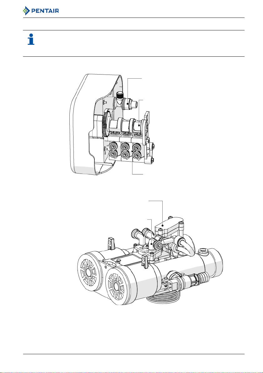
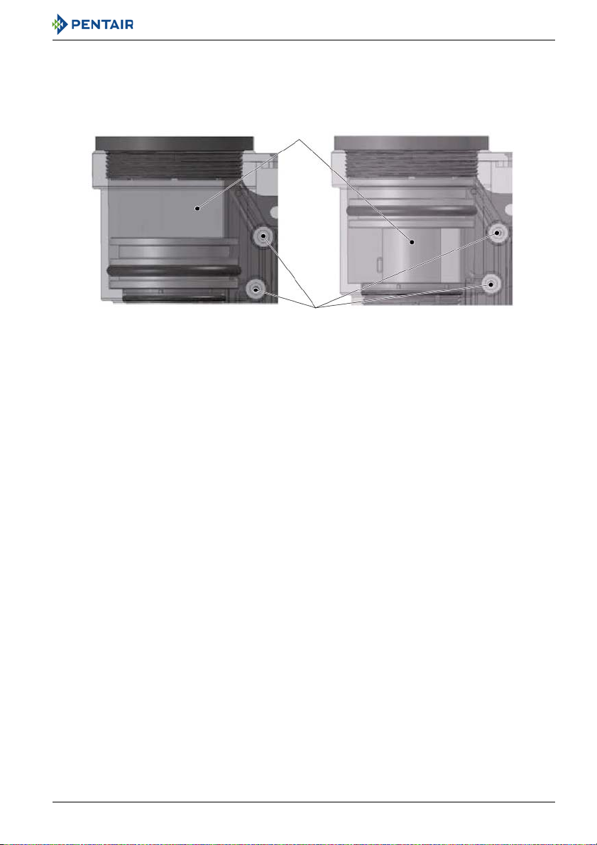
3.4.2. Valve with external pilots
Camshaft
Short manifold
External pilots
Brine valve
External pilots connections
Note
Only the components that differ from the twin pilots valve are described below.
Refer to chapter 3.4.1. Valve with twin pilots, page 18 for more information.
Installer Manual Siata V132-SFE-EV-VIRIDION - Description
Ref. MKT-IM-009 / C - 08.06.2018 19 / 110

Installer Manual Siata V132-SFE-EV-VIRIDION - Description
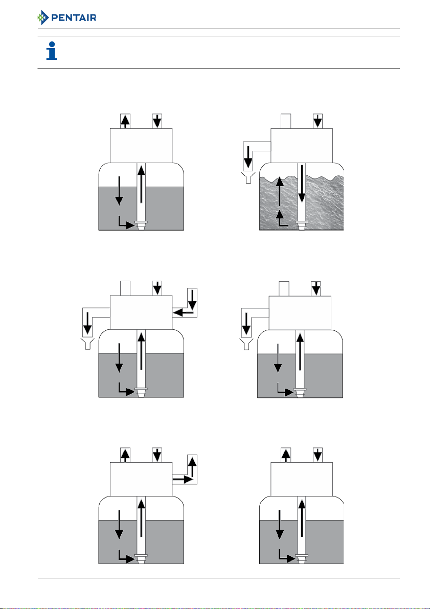
3.5. System regeneration cycle (5-cycle operation)
Service — normal use
Untreated water is directed down through the resin bed and up through the riser tube. The hardness
ions attach themselves to the resin and are removed from the raw water being exchanged on the resin
beads against sodium ions. The water is conditioned as it passes through the resin bed.
Backwash — cycle C1
The flow of water is reversed by the valve and directed down the riser tube and up through the resin
bed. During the backwash cycle, the bed is expanded and debris is flushed to the drain, while the
media bed is remixed.
Brine draw— cycle C2
The controller directs water through the brine injector and brine is drawn from the brine tank. The
brine is then directed down through the resin bed and up through the riser tube to the drain. The
hardness ions are displaced by sodium ions and are sent to the drain. The resin is regenerated during
the brine cycle. Then the slow rinse phase starts.
Slow rinse — cycle C3
The slow rinse cycle allows the brine to be slowly pushed into the resin bed, enabling regeneration of
the resin.
Rapid rinse — cycle C4
The valve directs water down through the resin bed and up through the riser tube to the drain. Any
residual brine is rinsed from the resin bed, while the media bed is recompacted.
Tank refill — cycle C5
The SFE-EV-VIRIDION timer automatically calculate the refill cycle duration. Water is directed to the
brine tank, though the BV, at a flow rate controlled by the refill controller [BLFC], to create brine for
the next regeneration. During brine refill, treated water is already available at the valve outlet.
Note
Depending on controller programming (see 6.4.3. Advanced programming, variables:
Variable brining function & “BLFC size”, page 62), the refill cycle is performed before the
regeneration start, in this case refill is indicated as cycle 1B or after the cycle 4C, in this case
is indicated as cycle 5C.
In case refill is performed before the regeneration, after the 1B cycle is completed, the
controller & the valve will be still in service for a relative short time in order to wait the
necessary time to dissolve the salt in the refilled water.
20 / 110 Ref. MKT-IM-009 / C - 08.06.2018
Installer Manual Siata V132-SFE-EV-VIRIDION - Description
From brine
tank
C2 + C3
BRINE DRAW & SLOW RINSE
C1
BACKWASH
SERVICE
NORMAL USE
C5
BRINE REFILL
Valve
SERVICE
NORMAL USE
C4
RAPID RINSE
Outlet
Drain
Inlet
Valve
Outlet Inlet
Valve
Outlet Inlet
Valve
Outlet Inlet
Valve
Outlet Inlet
Valve
Outlet Inlet
To brine tank
Drain
Drain
Note
For illustration purpose only. Always verify inlet and outlet marking on the valve.
Ref. MKT-IM-009 / C - 08.06.2018 21 / 110
Installer Manual Siata V132-SFE-EV-VIRIDION - Description
Inlet Outlet
Drain Drain
Service flow diagram
Backwash flow diagram
Drain Drain
Brine draw diagram Slow rinse diagram
Drain
Fast rinse diagram
Drain
Refill diagram
Inlet Outlet
Inlet
Outlet
Inlet Outlet
Inlet Outlet
Inlet
Outlet
22 / 110 Ref. MKT-IM-009 / C - 08.06.2018
Installer Manual Siata V132-SFE-EV-VIRIDION - Description
1 - 1/2 turn
1/2 turn
3/4 turn
1 - 1/4 turn
1/4 turn
0
1 turn
3.6. Options available on the valve
Backwash flow regulators
Backwash flow regulator (1) is positioned in the lower part of the valve. It is accessed by unscrewing
protective cap (2).
Valves equipped with this accessory are fitted with a flow control set offering the following maximum
outputs:
Code
12085 1.2 4.5 272.5
12086 1.5 5.7 340.6
12088 2.4 9.1 545.0
12090 3.5 13.2 794.8
12092 5 18.9 1135.5
Mixing device
The valve can be equipped with a mixing device (3) whose function is to regulate the hardness of the
water at the outlet.
[gpm] [L/min] [L/h]
Max output
Ref. MKT-IM-009 / C - 08.06.2018 23 / 110

Installer Manual Siata V132-SFE-EV-VIRIDION - Description
Flow rate [l/min] at 15 °C
Mixing valve performance
Mixing valve opening position
1 [bar]
1.5 [bar]
2 [bar]
2.5 [bar]
3 [bar]
Note
There is no automatic bypass during a fast rinse cycle. But once the mixing device has been
set, it connects the inlet and outlet of the valve.
So during the fast rinse phase with a mixing device, it is possible that a flow of untreated
water flows into the outlet.
24 / 110 Ref. MKT-IM-009 / C - 08.06.2018
Installer Manual Siata V132-SFE-EV-VIRIDION - Description
Pilot chamber under pressure
Driver replica
Additional hydraulic controls (driver replica)
The valve can be equipped with two pairs of connectors for duplicating the position of the hydraulic
controls. In order to use the valve, which is delivered with this option, simply remove the blue plugs,
at the bottom of the valve, to put a 6 mm flexible tube into the quick connections.
Probe
The SFE-EV-VIRIDION controller can grant significatively water savings, with a probe, during slow
rinse and fast rinse phases by comparing the instantaneous conductivity of the water (Ci) flowing
through valve drain with the one previously recorded.
Ref. MKT-IM-009 / C - 08.06.2018 25 / 110
Installer Manual Siata V132-SFE-EV-VIRIDION - System sizing
4. System sizing
4.1. Recommendations
4.1.1. Injector/DLFC/BLFC-Valve configuration
Tank diameter Resin volume
[in] L
8 15 Brown 1 350 1.5
10 30 Blue 2 480 2.1
10 50 Blue 3 700 3.1
13 70 Red 4 950 4.2
14 100 Red 4 950 4.2
16 120 Black 5 1450 6.4
18 150 Black 5 1450 6.4
Injector DF
No. DLFC
Washer
4.2. Sizing a softener (single unit)
4.2.1. Parameters to be considered
Whenever installing a softener, it is preferable to have full water analysis to ensure the inlet water
content will not affect the resin bed.
Note
Please consult your resin manufacturer specifications to ensure that no additional
pretreatment prior to softening is required.
DLFC
[l/h] [gpm]
26 / 110 Ref. MKT-IM-009 / C - 08.06.2018
Installer Manual Siata V132-SFE-EV-VIRIDION - System sizing
The below sizing method can be applied for both residential and industrial softeners.
The sizing of a softener must be based upon certain parameters:
• inlet water hardness;
• peak flow rate and nominal flow rate;
• service velocity;
•salt dosage.
The softening and regeneration reactions are driven under certain conditions. To allow these
reactions to take place, make sure that the velocity is convenient during the different phases for
proper ion exchange. This velocity is given in the resin manufacturer specifications sheet.
Depending on the inlet water hardness, the service velocity for standard softening must be between:
Service velocity
[bed volume per hour]
Inlet water hardness
[mg/l as CaCO
]
3
°f
°TH
°dH
8 - 40 <350 <35 <19.6
8 - 30 350 to 450 35 - 45 19.6 - 25.2
8 - 20 >450 >45 >25.2
Note
Failure to respect the service velocity will lead to hardness leakage or even total softener
inefficiency.
Note that the water supply piping size may also be useful when estimating the nominal flow rate, since
the size of the piping allows a maximum flow rate to pass. Assuming the maximum velocity of water
in pipes is about 3 m/s, a good estimation for most common pressure [3 bar] and temperature [16°C]
is:
Piping size (internal diameter) Max. flow rate
[in] [mm]
[m3/h at 3 m/s]
0.5 12 1.22
0.75 20 3.39
1 25 5.73
Ref. MKT-IM-009 / C - 08.06.2018 27 / 110
Installer Manual Siata V132-SFE-EV-VIRIDION - System sizing
Piping size (internal diameter) Max. flow rate
[in] [mm]
[m3/h at 3 m/s]
1.25 32 8.69
1.5 40 13.57
2.0 50 21.20
2.5 63 34.2
3.0 75 49.2
4.2.2. Determining the required volume of resin
When sizing a softener, make sure that the volume of resin in the tank (bed volume) will be sufficient
so that even when the peak flow rate is reached, the velocity is still between the above values
depending on the hardness. When sizing a softener, always choose the resin volume and tank size
based on the peak flow rate but not on the nominal flow rate.
Note
Sizing on the nominal flow rate without taking the peak flow rate into account would result
in choosing smaller tank size and resin volume, and may lead in severe hardness leakage
during the service cycle when the peak flow is reached.
The maximum softened water flow rate that a softener can produce is given by the following formula:
Q
service max
= Fs
service
x BV
with:
Q
Fs
BV: bed volume of resin [m
: service flow rate [m3/h]
service max
: service velocity [BV/h]
service
3
]
Knowing this required volume of resin, it is possible now to determine the tank you need. Note that at
least a third of the total volume of the tank must be kept as free space so that the bed expansion
during backwash is sufficient to ensure correct cleaning of the resin.
28 / 110 Ref. MKT-IM-009 / C - 08.06.2018
Installer Manual Siata V132-SFE-EV-VIRIDION - System sizing
4.2.3. Resin exchange capacity and capacity of the unit
The resin exchange capacity and capacity of the unit are two different things that should not be
confused. The resin exchange capacity is the amount of Ca
of resin, which will depend on the resin type and salt dosage, whereas the capacity of the unit is the
capacity of the system, which will depend on the volume of resin and resin exchange capacity.
Knowing the required volume of resin, you can determine the exchange capacity of the unit. The
capacity of the unit can be expressed in different ways:
• the mass capacity, which corresponds to the weight in equivalent CaCO
resin, expressed in kg as CaCO
;
3
• the volume capacity, which represents the maximum amount of water that can be treated
between 2 regenerations. This last capacity takes into account the hardness of the water to be
treated and is expressed in m
3
or litres;
• the combined capacity, which represents the volume of water that could be treated between 2
regenerations if the inlet hardness is 1 °f or °dH. This capacity is expressed in °f.m
The resin exchange capacity will depend on the amount of salt to be injected into the resin bed during
the regeneration. This amount of salt is given in grams per litre of resin. The next table is showing the
resin exchange capacity in function of the amount of salt for a system with standard efficiency
regeneration.
Resin exchange capacity as a function of the salt dosage:
Salt amount
[g/L
]
resin
Corresponding resin exchange
capacity in [g/L
resin
] as CaCO
50 29.9 2.99 1.67
60 34 3.4 1.9
70 37.5 3.75 2.09
80 40.6 4.06 2.27
90 43.4 4.34 2.42
100 45.9 4.59 2.56
110 48.2 4.82 2.69
120 50.2 5.02 2.8
130 52.1 5.21 2.91
140 53.8 5.38 3.01
150 55.5 5.55 3.1
2+
and Mg2+ that can be retained by 1 litre
that can be fixed on the
3
3
or °dH.m3.
3
°f.m
[per L
3
resin
]
°dH.m
[per L
resin
3
]
Ref. MKT-IM-009 / C - 08.06.2018 29 / 110
Installer Manual Siata V132-SFE-EV-VIRIDION - System sizing
Salt amount
[g/L
]
resin
Corresponding resin exchange
capacity in [g/L
170 58.5 5.85 3.27
200 62.7 6.27 3.5
230 66.9 6.69 3.74
260 71 7.1 3.97
290 75.3 7.53 4.21
To calculate the system mass capacity:
M
= V
capacity
resin
x C
resin ex
To calculate the system combined capacity:
C
= V
capacity
resin
x C
cor resin ex
To calculate the system volume capacity:
V
capacity
= M
capacity
/ TH
inlet
or
V
capacity
= C
capacity
/ TH
inlet
resin
] as CaCO
with:
M
capacity
V
resin
C
resin ex
with:
C
capacity
V
resin
C
cor resin ex
capacity [°f.m
with:
V
capacity
M
capacity
C
capacity
TH
inlet
3
°f.m
[per L
3
: system mass capacity [g as CaCO3]
: volume of resin [L]
: resin exchange capacity [g/L
: system combined capacity [°f.m3 or °dH.m3]
: volume of resin [L]
: corresponding resin exchange
3
/l or °dH.m3/l]
: system volume capacity [m3]
: system mass capacity [g as CaCO3]
: system combined capacity [°f.m3 or °dH.m3]
: inlet water hardness [mg/L as CaCO3 or °f or °dH]
resin
]
resin
°dH.m
[per L
as CaCO3]
resin
3
]
Caution
If a mixing device is set on the valve before meter, TH = TH
INLET
- TH
OUTLET
.
Having determined the previous capacity allows the operator to know the service cycle duration.
30 / 110 Ref. MKT-IM-009 / C - 08.06.2018
 Loading...