

SHURFLO
®
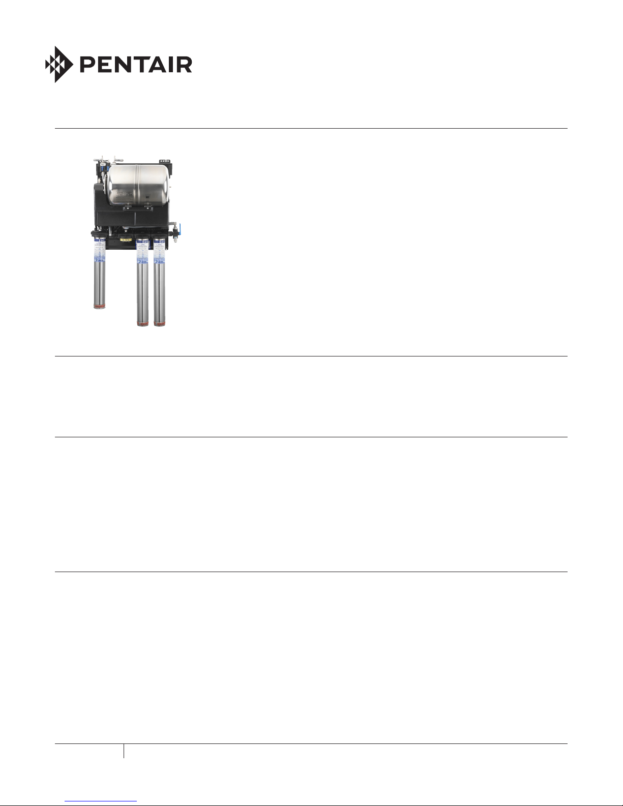
WATER BOOST MODULAR FILTRATION SYSTEMS
INTRODUCTION
Pentair® Shurflo® has applied its expertise and years of experience in pump technology to provide a safe and reliable
diaphragm pump. Every Pentair Shurflo pump is 100% tested for proper flow, pressure, and performance before it leaves
the factory. Although this tested design will provide years of trouble-free and economical operation, you should use care in
installing your system.
SYSTEM DESCRIPTION AND FUNCTION
The Pentair Shurflo water boost modular filtration system is designed to integrate both the water boost and water filtration
systems into one easy to install component, thus guaranteeing proper placement of the water boost system in relation to
the filtration system. The system consists of a Pentair Shurflo 8000 diaphragm pump and accumulator tank which function
together to boost the water pressure to the filtration system. The boosted water pressure not only assures an adequate water
supply to the fountain system but maximizes utilization of the filter elements throughout their service life.
The pump, accumulator tank and filtration system are NSF listed.
The system comes mounted on a steel panel which design includes Pentair Shurflo patented slide track design requiring
minimal steps for installation and startup.
FEATURES
• Pentair Shurflo patented slide track design for wall mounting or rack mounting
• NSF listed components
• 115 VAC
• All plumbing connections are located on the upper left of the unit
• City Water Inlet: 3/8" barb
• Water Outlet to Ice Maker Feeder (non-boosted, non-filtered): 3/8" barb
• Water Outlet (2): 3/8" barb
FOODSERVICE
SHURFLO WATER BOOST MODULAR FILTRATION SYSTEM INSTALLATION AND OPERATION GUIDE
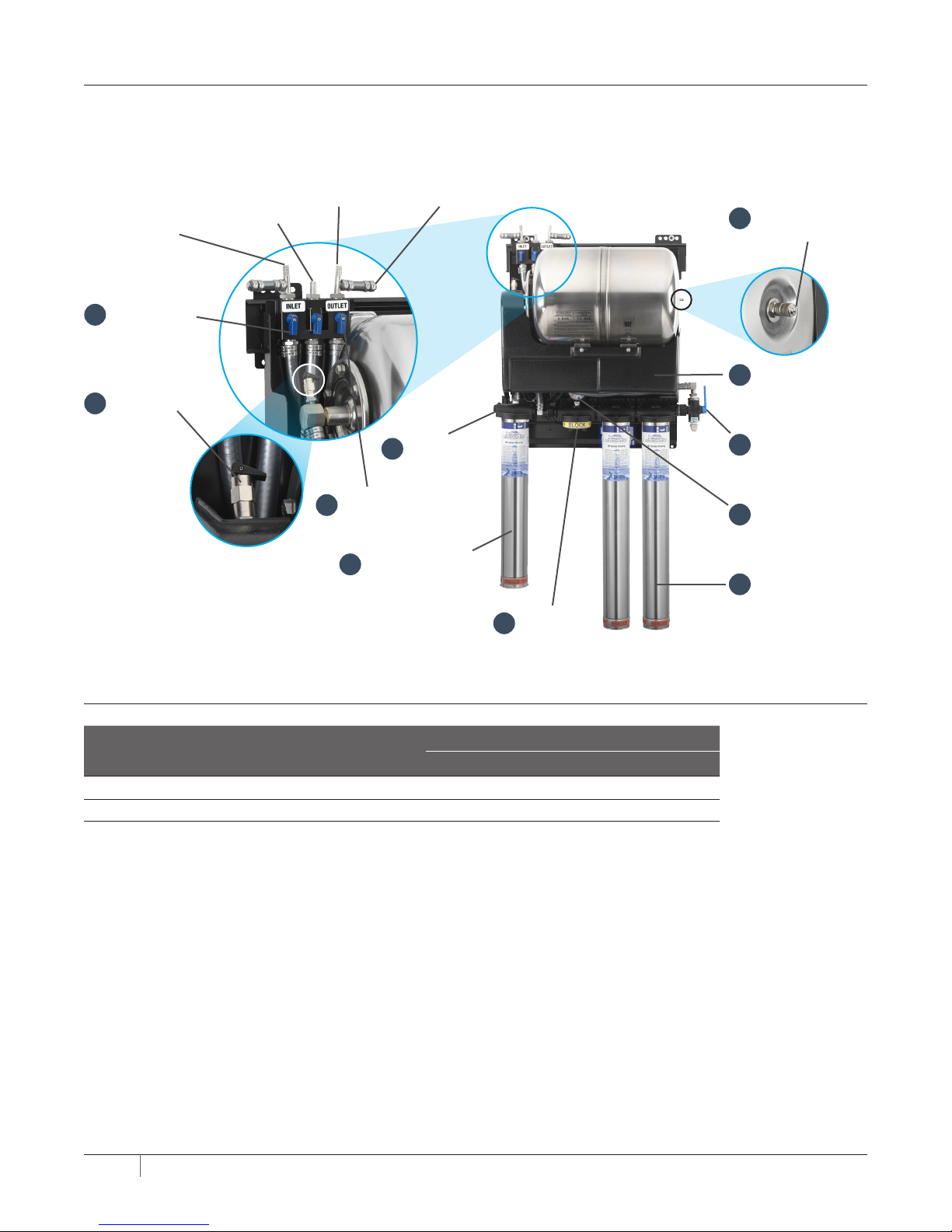
SYSTEM IDENTIFICATION
WATER BOOST MODULAR FILTRATION (WBMF) SYSTEM
Water Out
to Carbonator
Main City
Water Inlet
City Water In
1
Ball Valve
Pressure Relief
2
Valve
Ice Maker
Water Supply*
4
WBMF System Out
3
Ball Valve
Ice Filter Canister
11
stainless steel sump
*Ice Maker Water Supply is non-boosted/non-filtered
Water Out
Non-Carb System
Filter Head
Assembly
5
Bypass
Plug/Cap
Tank Pre-charge
10
Valve and Cap
Booster Pump
9
(behind shroud)
Purge Valve
8
w/o drain tubing
attached
Filtered Water
7
Pressure Gauge
Filter Canister
6
stainless steel sump
SYSTEM CONFIGURATIONS
WBMF Model #
WB6-M3-22-003-SS 6 3 in parallel bypass plug 122TO5 122TO5
WB6-M3-22-003-SSPLUS 6 3 in parallel 122PLUS 122PLUS 122PLUS
Tank
(gallons)
Filter System
Configuration
Head 1 Head 2 Head 3
Filter Media Elements
2 SHURFLO WATER BOOST MODULAR FILTRATION SYSTEM INSTALLATION AND OPERATION GUIDE
SYSTEM COMPONENTS
Filter System
Design
Modular filter head design with patented locking system and quick connect couplers for parallel or
series water flow
Inlet Port 3/8" barb
Outlet Port 3/8" barb
Pressure Gauge 0 –160 psi incremental pressure gauge (measures outlet pressure)
Min./Max. Operating Pressure 20 psi (1.4 bar) / 125 psi (8.6 bar)
Min./Max. Water Temperature 40˚F / 100˚F (4.4˚C / 37.8˚C)
Filter Element Housing
Design Bayonet style dry sump
Materials of Construction 304 Stainless steel
Filter Element
Design Sealed replacement dry sump style filter element
Materials of Construction Polypropylene
SPECIFICATIONS
Water Boost System WB6 - Series System Dimensions and Weights
Booster Pump 90 psi, 115 VAC diaphragm design pump Triple
Booster Pump Materials Viton® valves, Santoprene® diaphragm, nylon housing Shipping Weight 44 lbs
Accumulator Tank Materials Stainless steel housing with butyl rubber bladder Operating Weight 61 lbs
Accumulator Tank Size 6 gallons (WB6 – series) Overall Dimensions* 18.5" x 41"x 12.5"
Accumulator Tank Pre-charge 50 psi
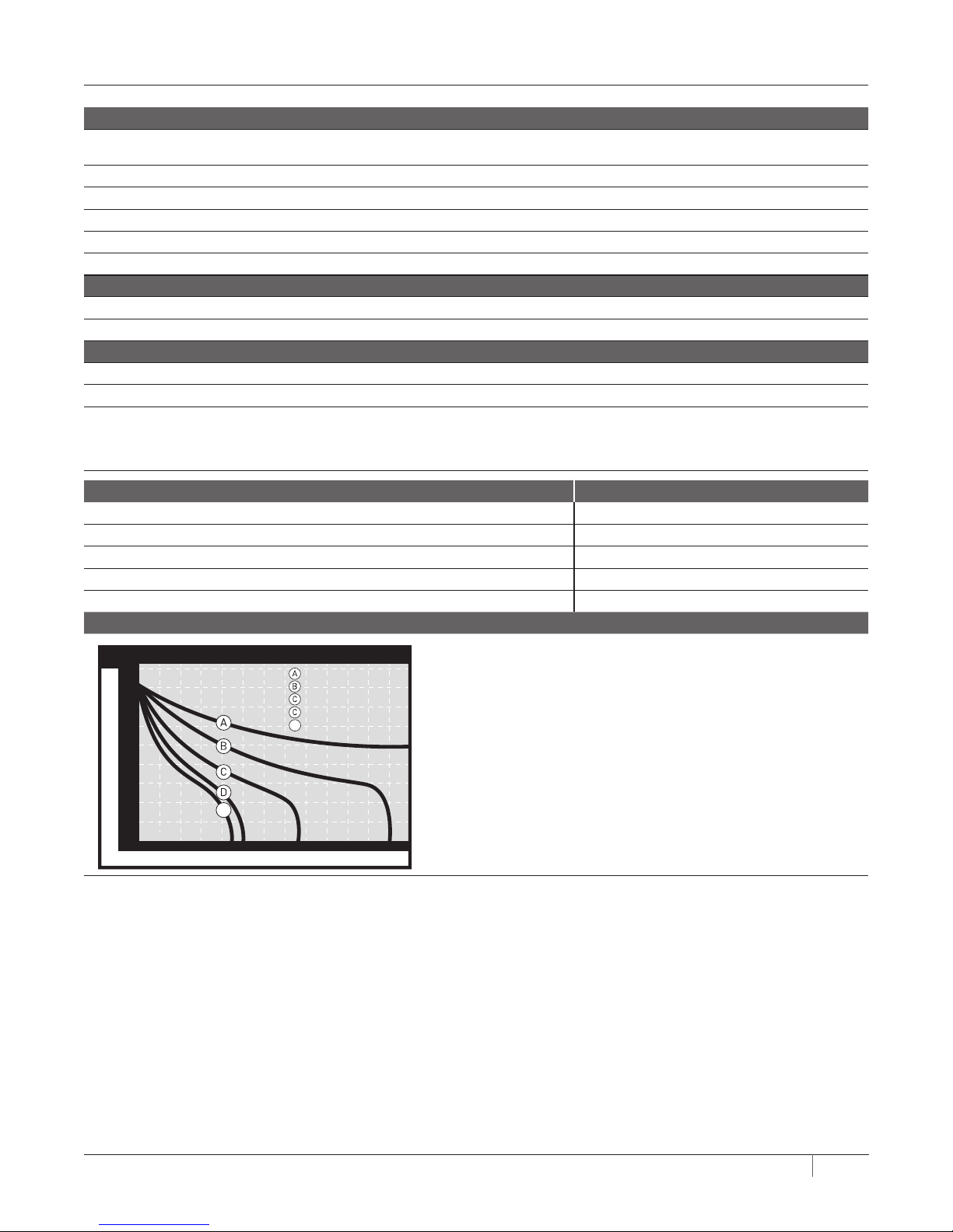
WB6 – Series Water Boost performance
100
6.9
90
6.2
80
5.5
70
4.8
60
4.1
50
3.4
40
2.8
Pressure (PSI/Bar)
30
2.1
20
1.4
10
0.7
6 Gallon Maxi Water Boost
Flow Rate
E
E
10 20 30 40 50 7060 80 90 100 110 120
Time (Seconds)
4.0 oz p/sec (118 ml p/sec)
6.0 oz p/sec (177 ml p/sec)
8.0 oz p/sec (237 ml p/sec)
10.0 oz p/sec (296 ml p/sec)
12.0 oz p/sec (355 ml p/sec)
*Allow an additional 3” vertical clearance below housing for filter element change.
3 SHURFLO WATER BOOST MODULAR FILTRATION SYSTEM INSTALLATION AND OPERATION GUIDE

PERFORMANCE DATA
Important Notice: Read this performance data and compare the capabilities of this system with your actual water treatment
needs. It is recommended that, before installing a water treatment system, you have your water supply tested to determine
your actual water treatment needs.
This system has been tested according to NSF/ANSI 42 for the reduction of the substances listed below. The concentration
of the indicated substances in the water entering the system was reduced to the concentrations less than or equal to the
permissible limit for water leaving the system, as specified in NSF/ANSI 42.
MOD30422/MOD122TO5
Substance
Standard 42 Aesthetic Effects
Chlorine 2.0 mg/L ± 10% ≥50% 97.4%
Particulate Class III
particles 0.5 to <1 m
Flow Rate = 7.5 gpm (26.87 lpm) Capacity = 60,000 Gallons (227,124.7 liters)
Influent Challenge
Concentration
at least 10,000
particles/mL
Maximum Permissible
Product Water
Concentration Reduction Requirements Average Reduction
≥85% 99.8%
MOD30422/MOD122PLUS
Maximum Permissible
Product Water
Concentration Reduction Requirements Average Reduction
Substance
Standard 42 Aesthetic Effects
Chloramines
1
Influent Challenge
Concentration
3.0 mg/L ± 10% 0.5 mg/L 97.81%
Chlorine 2.0 mg/L ± 10% ≥50% 97.81%
1
As monochloramine (measured as Cl2 /L) Flow Rate = 5.1 gpm (19.3 lpm) Capacity = 6,450 Gallons (24,415.9 liters)
TEST CONDITIONS OPERATING REQUIREMENTS
Inlet Pressure = 60 ± 3 psig (4.13 bar) Pressure = 20-125 psi (1.4-8.62 bar)
pH = 7.5 ± 0.5 Temperature = 40-100° F (4.4-37.8° C)
Temperature = 68 ± 5°F (20 ± 3°C)
Testing was performed under standard laboratory conditions, actual performance may vary.
4 SHURFLO WATER BOOST MODULAR FILTRATION SYSTEM INSTALLATION AND OPERATION GUIDE
 Loading...