

Pentair SHURFLO 5059 series, SHURFLO 5059-1310 series, SHURFLO 5059-1311 series Installation, Operation, Repair And Parts Manual
5059 Industrial Series Pumps
®
®
SHURFLO
Installation, Operation, Repair and Parts Manual
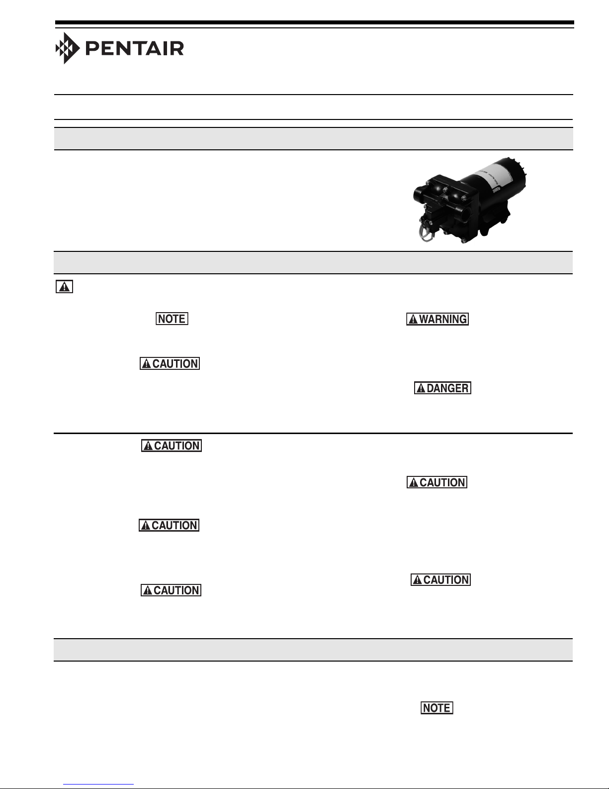
Description
SHURflo offers various pump models for different applications. The information
outlined by this manual is general and not specific to all 5059 series pumps.
Be certain the pump’s materials will be compatible with the fluid being pumped.
The 5059 series pumps are intended for intermittent or continuous duty when
the proper operating criteria are met. Product data sheets outlining specific
thermal limits, load, flow curves, and other technical information for a particular
model are available. If unsure of the chemical compatibility with a given elastomer or the motors intended design, please call SHURflo for assistance.
General Safety Information
California Proposition 65 Warning -- This product and related accessories contain chemicals known to the State of
California to cause cancer, birth defects or other reproductive harm.
orm 911-1051
F
Rev. B
Notes are used to notify of installation, operation, or
maintenance information that is important but not safety
related.
Caution is used to indicate the presence of a hazard,
which will or may cause minor injury or property damage
if the notice is ignored.
"Intermittent Duty" is defined as: operated and/or frequently started within a period of time that would cause the
motor to reach its maximum thermal limits. Once the
maximum thermal limit is obtained, the motor must be
allowed to return to ambient temperature before resuming
operation.
DO NOT use to pump flammable liquids. Never operate the
pump in an explosive environment. Arcing from the motor
brushes, switch or excessive heat from an improperly
cycled motor may cause an explosion.
DO NOT assume fluid compatibility. If the fluid is improperly matched to the pump’s elastomers, a leak may occur.
Pumps used to transfer hazardous or hot (max. tempera-
Warning denotes that a potential hazard exists and indicates procedures that must be followed exactly to either
eliminate or reduce the hazard, and to avoid serious
personal injury, or prevent future safety problems with the
product.
Danger is used to indicate the presence of a hazard that
will result in severe personal injury, death, or property
damage if the notice is ignored.
ture 120°F [49°C] viton only) chemicals must be in a
vented area to guard against the possibility of injury due
to harmful or explosive liquid/vapors.
DO NOT operate the pump at pressures which cause the
motor to exceed the amperes rating indicated on the name
plate. Various pump models are equipped with thermal
breakers to interrupt operation due to excessive heat.
Once the temperature of the motor is within proper limits,
it will automatically reset, and the pump will start
operation without warning.
To prevent electrical shock, disconnect power before
initiating any work. In the case of pump failure, the motor
housing and/or the pumped fluid may carry high voltage to
components normally considered safe.
1. Always drain and flush pump before servicing or disassembling for any reason (see instructions).
2. Always drain and flush pump prior to returning unit for repair.
3. Never store pumps containing hazardous chemicals.
Hazardous Substance Alert
4. Before returning pump for service/repair, drain out all liquids
and flush unit with neutralizing liquid. Then, drain the pump.
Attach tag or include written notice certifying that this has
been done.
It is illegal to ship or transport any hazardous chemicals without United States Environmental Protection Agency Licensing.
Pressure Switch Operation
The pressure switch reacts to outlet pressure and interrupts power at the preset shut-off pressure indicated on
he pump label. When outlet pressure drops below a pre-
t
determined limit (typically 15-20 psi [1-1.4 bar] less than
the shut-off pressure), the switch will close and the pump
will operate until the shut-off (high) pressure is achieved.
The shut-off pressure is set to factory calibrated stan-
ards. See the motor label for specific pump specifica-
d
tions.
Bypass Operation
Improper adjustment of the pressure switch may cause
severe overload or premature failure. Failures due to
improper adjustment of the pressure switch will not be
covered under the limited warranty.
If the plumbing is restrictive or the flow rate is very low, the
pump may re-pressurize the outlet faster than the fluid is
being released, causing rapid cycling (ON/OFF within 2
seconds). If the pump is subjected to rapid cycling during
normal operation, damage may occur. Applications which
exhibit rapid cycling should have restrictions in the outlet
minimized.
A bypass pump may be used for applications that normally induce frequent start/stop of the motor, and thereby create a potential for overheating. Models equipped with an
internal bypass are designed to pump at high pressure
while at low flow rates.
Mounting
The 5059 series pumps are self priming. Horizontal and
vertical prime vary depending on the fluid viscosity and
pump configuration.
The pump should be located in an area that is dry and provides adequate ventilation. If mounted within an enclosure, provisions to cool the motor may be necessary.
Heat sinks, which attach to the motor, are available from
SHURflo if increased heat dissipation is necessary.
Plumbing
Flexible high pressure tubing compatible with the fluid
should be used to connect the inlet/outlet ports. Tubing
should be 1/2" [13 mm] I.D. and at least an 18 in. [46 cm]
length is suggested to minimize stress on the fitting/ports
and reduce noise. Allow for the shortest possible tubing
route and avoid sharp bends that may kink over time.
Restrictions on the inlet may cause vacuum levels to
reach the fluid vapor pressure, causing cavitation,
degassing, vapor lock, noise, and a loss in performance.
Inlet pressure must not exceed 30 psi [2.1 bar] maximum.
SHURflo does not recommend the use of metal fittings or
rigid pipe to plumb the inlet/outlet ports. Standard plastic
male and female-threaded fittings can be acquired at
commercial plumbing supply stores. SHURflo also distributes swivel barb fittings and special fittings through its
dealers.
Bypass models equipped with a switch may operate for
several seconds even though the outlet side has been
closed off. Contact SHURflo for information regarding
bypass pumps.
DO NOT locate the motor near low temperature plastics or
combustible materials. The surface temperature of the
motor may exceed 250°F [120°C].
The pump may be mounted in any position. However, if
mounting the pump vertically, the pump head should be in
the down position so that in the event of a leak, fluid will
not enter the motor.
Secure the rubber feet with #8 hardware. DO NOT compress the feet: doing so will reduce their ability to isolate
vibration/noise.
1/2" Female NPT models: In some cases, the ports may require
a suitable thread sealer applied sparingly. DO NOT over-tighten,
max. torque 3.7 ft. lbs. [45 in. lbs. (5 Nm)].
1/2" Male-threaded models are intended to be used with SHURflo
swivel barb fittings which seal with an internal taper when handtightened. Standard 1/2" NPT fittings may be used when tightened
to a maximum torque of 3.7 ft.lbs [45 in.lbs (5 Nm)].
Sealers and Teflon tape may act as a lubricant, causing cracked
housings or stripped threads due to over-tightening. Care should
be used when applying sealers. Sealers may enter the pump,
inhibiting valve action, causing no prime or no shut-off. Failures
due to foreign debris are not covered under warranty.
Installation of a 50-mesh strainer is recommended to prevent foreign debris from entering the pump.
If a check valve is installed in the plumbing, it must have a cracking pressure of no more than 2 psi (.14 bar).
2
 Loading...