

SHURFLO® 3200 MACERATOR PUMP
INSTALLATION, OPERATION & REPAIR MANUAL
SHURFLO’s macerator pump is designed to empty marine and RV holding tanks of normal waste. It is also an excellent choice
for emptying fi sh boxes of scales and residual waste. A fl ow rate of up to 13 gallons per minute conveniently empties any tank
in minutes. The unique dual-cut blade design ensures waste is ground up thoroughly. The pump is self-priming to a fi ve foot lift
when impeller is wet, four foot lift when impeller is dry, but for optimum performance and life, it should be mounted as close to
the tank as possible. Marine pump out must be in proper discharge zones only. This macerator will not handle hard objects, rags,
or feminine napkins.
PRODUCT SPECIFICATIONS
Motor: Seamless can motor, 1/8 hp Thermally protected
Lead Wires: 14 GA
Fuse: See motor label for fuse size
Pump Type: Flexible Impeller
Duty Cycle: Intermittent duty only
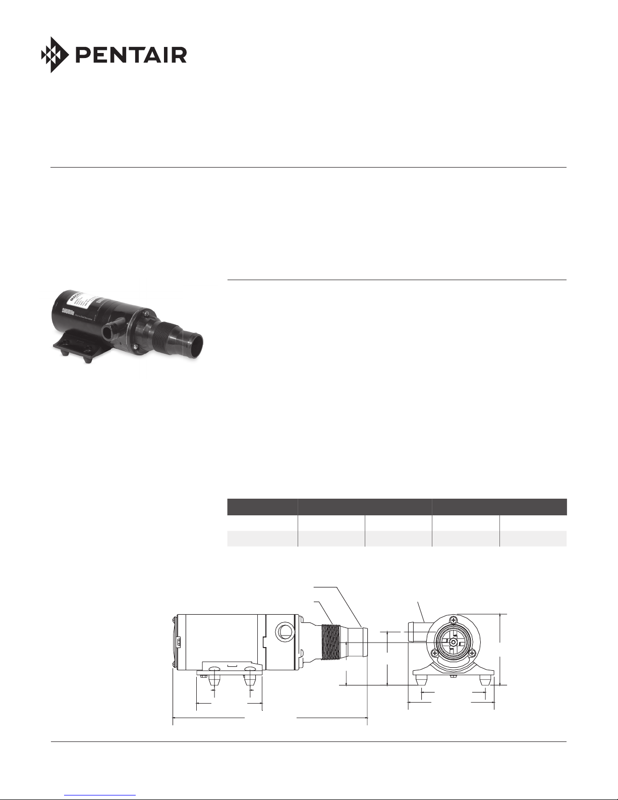
Ports: Inlet: 1-1/2” hose barb &
1-1/2” NPT Male
Outlet: 1” hose barb
Impeller: Brandonite
Blade: 316 stainless “Double-cut”
Dimensions: See drawing
Weight: 5 lbs.
Approvals: Ignition protected, ISO 8846, CE, and CSA, models available
Typical Flow: Dependent on fl uid viscosity (Chart below based on water)
®
911-566 REV. P 1
HEAD FLOW GPM [LPM] MAX. DC AMPS
Ft. [m] 12 V 24 V 12 V 24 V
0 [0] 13 [49] 13 [49] 17 9
Max. Operating Head = 30 feet
1-1/2" Hose Barb
1-1/2" NPT Male
2.0 [50.0]
3.6 [91.9]
10.8 [273.3]
2.3 [58.4]
1" Hose Barb
3.8 [97.3]
2.9 [72.9]
3.5 [89.7]
4.8 [120.9]

ELECTRICAL CONNECTIONS
WARNING: If the pump is operated in an
area containing flammable vapors, the
wire leads must be joined by insulated
mechanical locking connectors. Loose
or inadequate wire connections can
spark, resulting in an explosion resulting in property damage, injury, or death.
All electrical installations should be
done by a qualified electrician.
❚ Pump must be protected with proper
size fuse as specified on the motor
label.
❚ Pump should be operated on a separate circuit.
❚ Pump should be connected to properly
sized momentary switch. This prevents
pump from damage due to long periods
of dry run condition.
❚ Switch should be near pump. This will
allow operator to hear change in pump
sound when tank is empty.
AVERTISSEMENT: Si la pompe est
utilisée dans une zone contenant des
vapeurs inflammables, les fils doivent
être reliés par des raccords à verrouillage mécanique isolés. Des raccordements de fils desserrés ou inadéquats
peuvent produire des étincelles et
provoquer une explosion entraînant des
dommages matériels, des blessures ou
la mort. Toutes les installations électriques doivent être effectuées par un
électricien qualifié.
❚ La pompe doit être protégée par un
fusible de calibre approprié comme
précisé sur l’étiquette du moteur.
❚ La pompe devrait être utilisée sur un
circuit distinct.
❚ La pompe devrait être raccordée à un
interrupteur à rappel calibré correctement. Cela protège la pompe contre les
dommages attribuables à de longues
périodes de tournage à sec.
❚ L’interrupteur devrait se trouver
près de la pompe. Cela permettra à
l’utilisateur d’entendre un changement
dans le son de la pompe lorsque le
réservoir est vide.
NOTE: For proper operation motor must
rotate counterclockwise when viewed
from pump end.
2
ELECTRICAL INSTALLATION CHECKLIST
√ Separate circuit from power source
√ Proper size momentary switch
mounted near pump
√ Proper wire size to length
√ Proper fuse size and type
√ Insulated wire connectors
12 Volt System Min. Wire Size (20 Amps)
Total Wire Length* 3% Drop 10% Drop
Feet [m] GA GA
1-10 [.3-3] #10 #16
11-20 [3.3-6] #8 #14
21-30 [6.4-9.1] #6 #12
30-60 [9.1-18.2] #4 #10
*length from power source to motor and
back to ground.
PLUMBING CONNECTIONS
Pump should be mounted as near as possible to tank to minimize dry run. Pump is
self-priming to a five-foot lift when impeller is wet, four foot lift when impeller is dry.
Pump is more efficient if mounted near the holding tank. Installations should be
done by qualified marine tech.
INLET: Always install pump with a shut-off valve between pump and holding
tank.
Hose: Use 1-1/2” ID [non-collapsible vacuum rated] hose on inlet [suction]
side. Use stainless steel hose clamps on all sanitation connections.
Flange: To mount to 1-1/2” female flange, inlet barb must be cut off just before
threads. Seal threads and hand tighten.
WARNING: Any air leak on inlet side can cause pump to run dry and can damage
impeller and impeller housing. Check all inlet side connections, even those on deck
plates. All runs should be smooth with no kinks or sharp angles.
AVERTISSEMENT: Une fuite d’air sur le côté aspiration peut causer le tournage à
sec de la pompe et endommager la turbine et le boîtier de turbine. Vérifier tous les
raccordements sur le côté aspiration, même ceux sur les plaques de plateforme.
Tous les parcours doivent être lisses, sans tortillement ni angle aigus.
OUTLET: Use 1” minimum ID hose on discharge side of pump. Connect to thru
hull fitting above highest heeled point above waterline. Vented loop
installations must vent at least 10” above highest heeled point above
waterline. Use stainless steel hose clamps on all sanitation connec-
tions.
Operation: INTERMITTENT DUTY ONLY!
Pump switch must be near pump and tank so operator can hear pump running.
Make sure shut-off valve to pump and dump valve [if equipped] are both open. Turn
on momentary switch and pump out tank. When tank is empty, pump will get louder
with a high pitch sound. Immediately turn pump off, or damage to impeller and
housing will occur. Do not run pump dry for more than 15 – 20 seconds. Flush tank
and pump with water after each use. This macerator will handle normal waste, tissues, cigarettes, fish scales, etc. It is not designed to handle large hard objects such
as large bones or fruit pits.
Periodic Maintenance and Storage: Flush with water after each use. Check wire
connections occasionally. After periods of non-use, impeller can stick. To loosen,
open rear shaft cover and turn motor shaft clockwise with a flat tip screwdriver.
Then replace shaft cover. For extended periods of non-use, pump impeller can be
lubricated by running a small amount of mineral oil through holding tank system.
 Loading...