

OWNER’S MANUAL
Submersible Solids HandlingPumps
NOTICE D’UTILISATION
Pompes de puisard submersibles
pour matières solids
MANUAL DEL USUARIO
Bombas sumergibles para el
manejo de partículas sólidas
Installation/Operation/Parts
For further operating, installation,
or maintenance assistance:
Call 1-888-957-8677
English ...........Pages 2-8
293 WRIGHT STREET, DELAVAN, WI 53115 WWW.HYDROMATIC.COM
PH: 8889578677
© 2013 Pentair, Ltd. All Rights Reserved. HYD956 (07/15/13)
SHEF42M1, SHEF42A1
Installation/Fonctionnement/Pièces
Pour plus de renseignements
concernant l’utilisation, l’installation
oul’entretien:
Composer le 1 (888) 957-8677
Français ........Pages 10-16
Instalación/Operación/Piezas
Para mayor información sobre el
funcionamiento, instalación o
mantenimiento de la bomba:
Llame al 1-888-957-8677
Español .......Paginas 18-24
Safety • Specifications 2
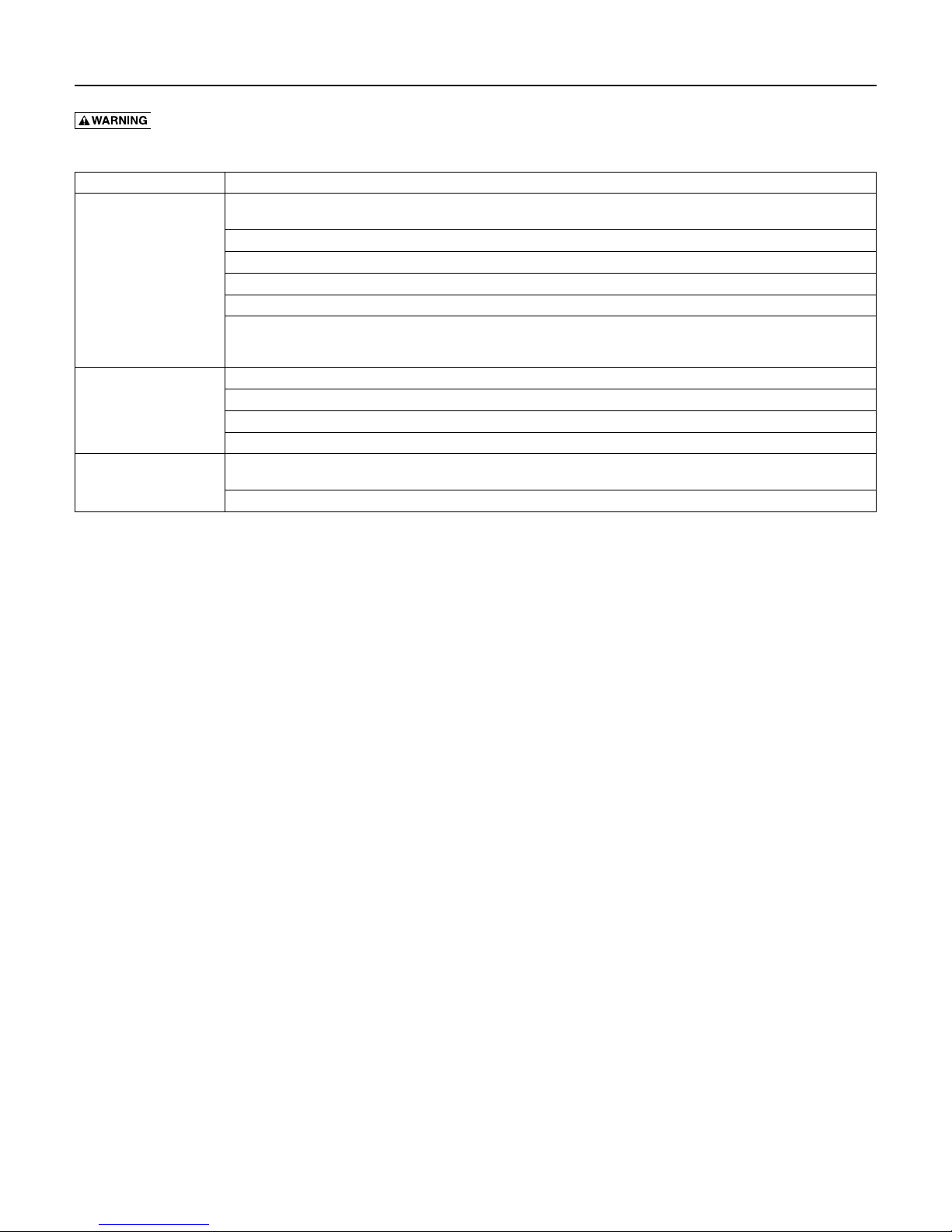
Important Safety Instructions
SAVE THESE INSTRUCTIONS - This manual contains
important instructions that should be followed during
installation, operation, and maintenance of the product.
Save this manual for future reference.
This is the safety alert symbol. When you see this
symbol on your pump or in this manual, look for one of
the following signal words and be alert to the potential
for personal injury!
indicates a hazard which, if not avoided, will
result in death or serious injury.
indicates a hazard which, if not avoided,
could result in death or serious injury.
indicates a hazard which, if not avoided,
could result in minor or moderate injury.
NOTICE addresses practices not related to
personalinjury.
Carefully read and follow all safety instructions in this
manual and on pump.
Keep safety labels in good condition. Replace missing or
damaged safety labels.
1. Read these rules and instructions carefully. Failure to
follow them could cause serious bodily injury and/or
property damage.
2. Check your local codes before installing. You must
comply with their rules.
3. Vent sewage or septic tank according to local codes.
4. Do not install pump in any location classified as
hazardous by National Electrical Code, or the
Canadian Electrical Code.
5. Risk of electric shock. Can shock, burn
or kill. During operation the pump is in water. To
avoid fatal shocks, proceed as follows if pump needs
servicing:
• Disconnect power to outlet box before
unplugging pump.
• Take extreme care when changing fuses. Do
not stand in water or put your finger in the
fusesocket.
• Do not modify the cord and plug. When using
the cord and plug, plug into a grounded outlet
only. When wiring to a system control, connect
the pump ground lead to the system ground.
6. Do not run the pump dry. Dry running can overheat
the pump, (causing burns to anyone handling it) and
will void the warranty.
7. The pump normally runs hot. To avoid burns when
servicing pump, allow it to cool for 20 minutes after
shut-down before handling it.
8. The pump is permanently lubricated. No oiling
or greasing is required in normal operation. for
overhaul, see instructions under Maintenance.
California Proposition 65 Warning
This product and related accessories contain
chemicals known to the State of California to cause
cancer, birth defects or other reproductive harm.
Description
These submersible sump/effluent and sewage pumps
are designed for effluent and wastewater removal, sump
drainage, dewatering, flood control, and so forth. Units
have built in thermal overload protection with automatic
reset. The mechanical seal and ball bearings on the
motor shaft are permanently lubricated. Stainless steel
hardware and a heavy duty lift out ring allow for easy
disassembly after extended use.
NOTICE This unit is not designed as a waterfall or
fountain pump, or for applications involving salt water or
brine! Use with waterfalls, fountains, salt water or brine
will void warranty.
Do not use where water recirculates.
Specifications
Power supply required...See Motor, Switch and Cord Specifications
Motor duty .............................. Continuous**
Maximum Liquid Temperature................130 °F (55 °C)
** For continuous duty pump must be fully submerged in a liquid
with a maximum temperature of 105° F (40.5° C).
Performance
GPM At Total Feet
Model
SHEF42M1 61 52 45 38 30 21 40
SHEF42A1 61 52 45 38 30 21 40
5 10 15 20 25 30 No flow at
Capacity Gallons/Minute
height shown
below
Motor, Switch, & Cord Specifications
Model
SHEF42M1
SHEF42A1 20 (6.1) 16.5 (419) 7.5 (191)
Motor
Voltage
HP
4/10 115/1 9.7 15
Full Load
Amps
Individual Branch Circuit
Required (Amps)
Cord Length
inft.(m)
20 (6.1) or 30 (9.1) N/A
Switch Setting in Inches (mm)
On Off
Discharge
Size
2”

Warranty 3
Limited Warranty
HYDROMATIC warrants to the original consumer purchaser (“Purchaser” or “You”) of HYDROMATIC Sump Pumps, Effluent
Pumps, Sewage Pumps (other than 2-1/2”), and Package Systems, that they will be free from defects in material and workmanship
for the Warranty Period of 36 months from date of manufacture.
Our warranty will not apply to any product that, in our sole judgement, has been subject to negligence, misapplication, improper
installation, or improper maintenance. Without limiting the foregoing, operating a three phase motor with single phase power
through a phase converter will void the warranty. Note also that three phase motors must be protected by three-leg, ambient
compensated, extra-quick trip overload relays of the recommended size or the warranty is void.
Your only remedy, and HYDROMATIC’s only duty, is that HYDROMATIC repair or replace defective products (at HYDROMATIC’s
choice). You must pay all labor and shipping charges associated with this warranty and must request warranty service through the
installing dealer as soon as a problem is discovered. No request for service will be accepted if received after the Warranty Period
has expired. This warranty is not transferable.
EXCEPTIONS: Hydromatic Special Application Pumps, Battery Back-Up Sump Pumps, Filtered Effluent Pumps, Grinder
Pumps, and 2-1/2” Sewage Pumps are warranted for a period of 12 months from date of purchase or 18 months from date of
manufacture, whichever comes first.
HYDROMATIC SHALL NOT BE LIABLE FOR ANY CONSEQUENTIAL, INCIDENTAL, OR CONTINGENT
DAMAGESWHATSOEVER.
THE FOREGOING LIMITED WARRANTIES ARE EXCLUSIVE AND IN LIEU OF ALL OTHER EXPRESS AND IMPLIED
WARRANTIES, INCLUDING BUT NOT LIMITED TO IMPLIED WARRANTIES OF MERCHANTABILITY AND FITNESS FOR
A PARTICULAR PURPOSE. THE FOREGOING LIMITED WARRANTIES SHALL NOT EXTEND BEYOND THE DURATION
PROVIDED HEREIN.
Some states do not allow the exclusion or limitation of incidental or consequential damages or limitations on the duration of an
implied warranty, so the above limitations or exclusions may not apply to You. This warranty gives You specific legal rights and
You may also have other rights which vary from state to state.
This Limited Warranty is effective June 1, 2011 and replaces all undated warranties and warranties dated before June 1, 2011.
HYDROMATIC
293 Wright Street, Delavan, WI 53115
Phone: 888-957-8677 • Fax: 800-426-9446 • Web Site: hydromatic.com
Installation 4
Risk of electric shock. Can shock, burn
or kill. Do not lift pump by the power cord. See Cord
LiftWarning.
NOTICE Install the pump on a hard, level surface
(cement, asphalt, etc.). Never place the pump directly on
earth, clay or gravel surfaces.
Piping
Piping must not be smaller than pump discharge.
When installed in a sewage system, the pipe must be
capable of handling semi-solids of at least 2” (51mm)
indiameter.
When installed in an effluent system, the pipe must be
capable of handling semi-solids of at least 3/4” (19mm)
in diameter.
The rate of flow in the discharge pipe must keep any
solids present in suspension in the fluid. To meet
minimum flow requirements (2 feet per second in the
discharge line), size the pipe as follows:
A Pipe Size Of: Will Handle a Flow Rate Of:
1-1/2” (38mm) 12 GPM
2” (51mm) 21 GPM
2-1/2” (64mm) 30 GPM
3” (76mm) 48 GPM
In a sewage system use a 2” (51mm) check valve (not
included) in pump discharge to prevent backflow of
liquid into sump basin. The check valve should be a
free flow valve that will easily pass solids. Be sure check
valve installation complies with local codes.
In an effluent system use a 1-1/2” (38mm) check valve
(not included) in pump discharge to prevent backflow
of liquid into sump basin. The check valve should be a
free flow valve that will easily pass solids. Be sure check
valve installation complies with local codes.
NOTICE For best performance of check valve when
handling solids, do not install it with the discharge more
than 45° above the horizontal. Do not install the check
valve in a vertical position as solids may settle in the
valve and prevent it from opening on startup.
Drill a 3/16” (5mm) hole in the discharge pipe about
1–2” (25-51mm) above the pump discharge connection
(but below check valve) to prevent airlocking the pump.
Electrical
Risk of electric shock. Can shock, burn or
kill. When installing, operating, or servicing this pump,
follow the safety instructions listed below.
1. DO NOT splice the electrical power cord.
2. DO NOT allow the electrical cord plug to
besubmerged.
3. DO NOT use extension cords. They are a fire hazard
and can reduce voltage sufficiently to prevent
pumping and/or damage motor.
4. DO NOT handle or service the pump while it is
connected to the power supply.
5. DO NOT remove the grounding prong from the
plug or modify the plug. To protect against electrical
shock, the power cord is a three-wire conductor and
includes a 3-prong grounded plug. Plug the pump
into a 3-wire, grounded, grounding-type receptacle.
Connect the pump according to the NEC or CEC and
local codes.
For automatic operation, plug or wire the pump into an
automatic float switch or duplex controller. The pump
will run continuously when plugged directly into an
electrical outlet.
Connect or wire pump to its own individual branch
circuit with no other outlets or equipment in the circuit.
Size fuses or circuit breakers according to Motor, Switch
and Cord Specifications.
Risk of electric shock. Can shock, burn or
kill. Be sure that power supply information (Voltage/
Hertz/Phase) on pump motor nameplate matches
incoming power supply exactly. Install pump according
to all electrical codes that apply.
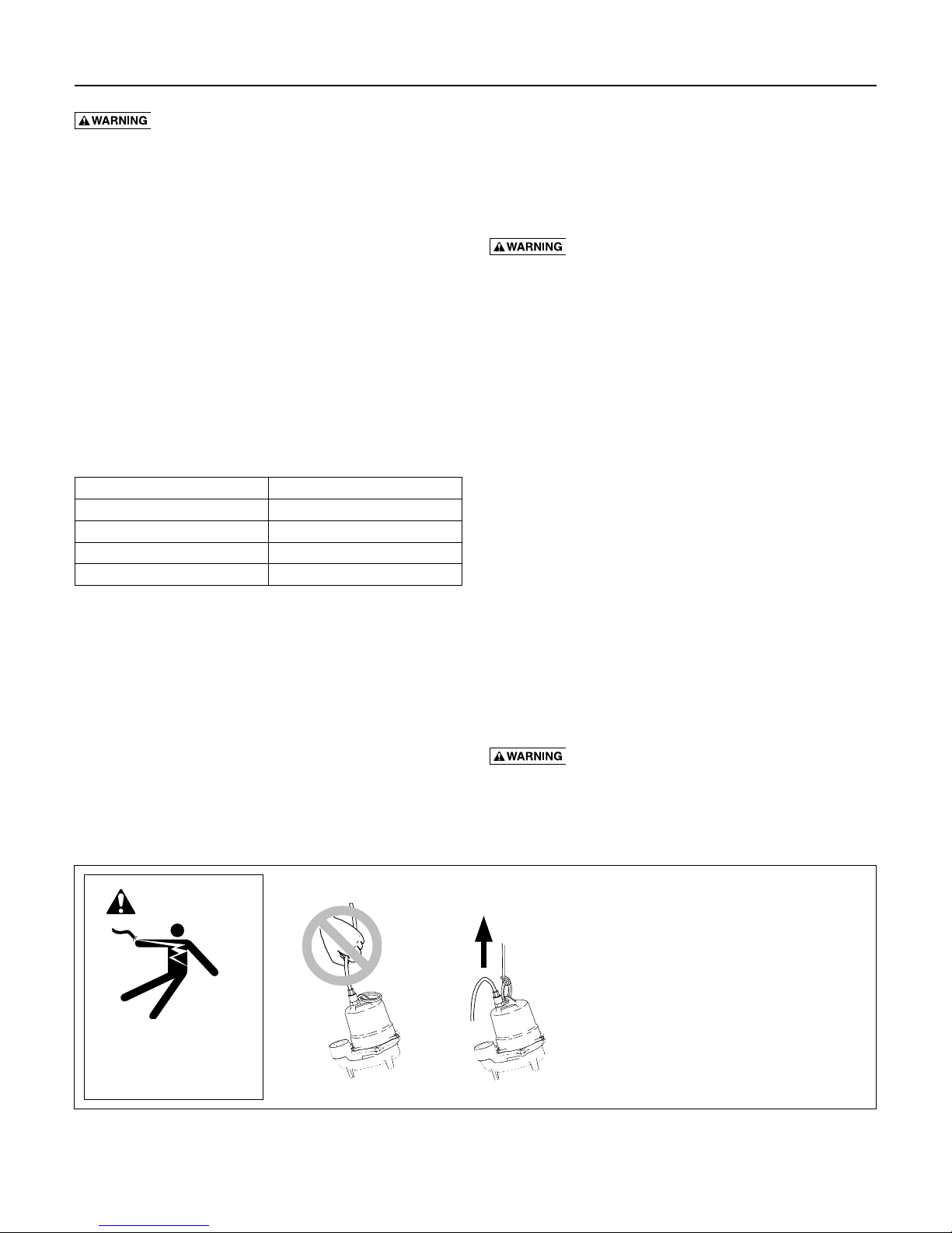
WARNING
Risk of electrical shock.
Can burn or kill.
Do not lift pump by
power cord.
Cord Lift Warning
1. Attempting to lift or support pump by power
cord can damage cord and cord connections.
2. Cord may pull apart, exposing bare wires
with possibility of fire or electrical shock.
3. Lifting or supporting pump by power cord
will void warranty.
4. Use lifting ring or handle on top of pump
for all lifting/lowering of pump. Disconnect
power to pump before doing any work
on pump or attempting to remove pump
fromsump.
Operation • Maintenance 5
Operation
Risk of fire and explosion. Can cause
severe injury, property damage or death. Do not use in
explosive atmospheres. Pump water only with this pump.
NOTICE Do not allow the pump to run in a dry sump. It
will void the warranty and may damage the pump.
An automatic overload protector in the motor will
protect the motor from burning out due to overheating/
overloading. When the motor cools down, the overload
protector will automatically reset and start the motor.
If the overload trips frequently, check for the cause.
It could be a stuck impeller, wrong/low voltage, or
an electrical failure in the motor. If an electrical
failure in the motor is suspected, have it serviced by a
competentrepairman.
The pump is permanently lubricated. No oiling or
greasing is required.
Maintenance
General
Risk of electric shock. Can shock, burn
or kill. Before removing the pump from the basin for
service, always disconnect electrical power to the pump
and the control switch. Do not lift the pump by the
power cord. See Cord Lift Warning.
After removing the basin cover and the necessary
discharge piping, lift the pump out of the basin.
Place the pump in an area where it can be cleaned
thoroughly. Remove all scale and deposits on the pump.
Submerge the complete pump in a disinfectant solution
(dilute chlorine bleach) for at least one hour before
disassembling the pump.
The pump motor housing contains a special lubricating
oil which should be kept clean and free of water at
alltimes.
NOTICE Whenever the motor housing is being removed
for service, remove oil and replace it with new oil at
reassembly. Use only oil listed in parts list in this manual.
When filling with new oil, DO NOT overfill. Allow about
7/8” (22mm) air space from top of boss in housing for
expansion of oil when the pump is operating.
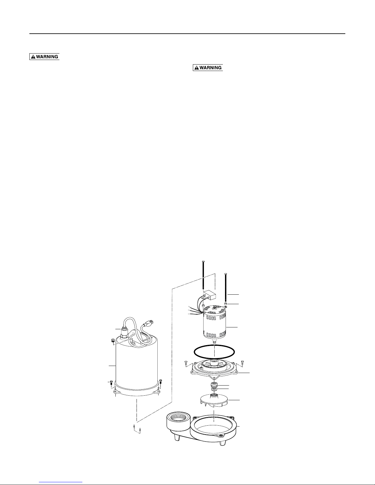
Power cord
connector
Oil fill plug
Upper motor
housing
Housing
capscrew
Pump Disassembly
See pump disassembly, Figure 1.
Rotor/Stator
Capscrew
Grn
Blk
Blk
Spacer
Rotor/Stator
Assembly
Shaft Seal, Stationary Head Assembly
Shaft Seal, Rotating Mating Ring
Impeller
Lower Motor
Housing
Figure 1 - Pump Disassembly
A
(See Fig. 2)
A
Volute

Maintenance 6
Green Wire
Impeller and seal replacement
1. Remove the oil fill plug and turn the pump upside
down to drain oil.
2. Remove the capscrews holding the upper motor
housing to the lower motor housing; lift off the
upper motor housing and remove the motor lead
wires from the connector to detach upper housing
from assembly. The lead wires are fitted with quick
connect terminals for this purpose.
3. Remove the capscrews holding the lower motor
housing to the volute; lift off the lower motor
housing.
4. Hold the rotor shaft assembly and unscrew the
impeller by turning it counter-clockwise. Remove
impeller and clean it.
If no more service is needed, reverse instructions
above to reassemble the pump. Reattach the motor
lead wires as shown in Figure 2, fill with clean SAE
5W-15W (ISO 22-44) mineral oil, check the oil level
and replace fill plug. Oil should cover the top of the
motor.
(connected between
the two tallest
dividers)
Either Black Wire
Short Divider
Either Black Wire
View A-A
Figure 2 - Motor Lead Wires
Shaft seal replacement
1. Follow the instructions to remove the
impeller,above.
2. Remove the stator capscrews and the spacers (if
applicable). Lift off the stator.
3. Remove the seal’s ceramic seat from the shaft
and tap the body of the seal out of the lower
motorhousing.
4. Clean the seal cavity thoroughly before installing the
new seal.
NOTICE Make sure that the seal faces are clean; do
not scratch or damage the new seal face during seal
replacement. Apply gasket sealant sparingly to the
outside edge of seal body before installing the seal in
the lower motor housing.
5. Press the new seal body into position in the lower
housing cavity.
6. Press the ceramic seat onto the motor shaft. The
impeller will pull it into position.
7. Reassemble the stator and tighten the stator
capscrews. If your pump has a capacitor (Repair
Parts Ref. 11), be sure the spacer is under it to keep
it away from the oil in the motor.
Risk of electric shock. Can shock, burn
or kill. Discharge capacitor before handling it.
Electrical shock can burn or kill.
8. Reassemble the impeller and the pump (reverse
instructions 1 through 4 in Impeller And
SealReplacement).
9. Install new capacitor.
10. Reattach the motor lead wires as shown in Figure 2.
11. Fill with fill with clean SAE 5W-15W (ISO 22-44)
mineral oil, check the oil level and replace the oil fill
plug.
Troubleshooting 7
Risk of electrical shock, cuts, and possible unexpected starts. If the power is on to the pump when
thermal overload resets, the pump may start without warning. If you are working on the pump, you may get an
electrical shock or the impeller may catch fingers or tools. Disconnect the power before servicing the pump.
Symptom Possible Cause(s) / Corrective Action
1. Check to be sure that power cord is securely plugged into outlet or securely wired into controller or switch box. Disconnect
power to outlet before handling pump or motor.
2. Check to be sure you have electrical power.
3. Check that liquid fluid level is high enough to activate switch or controller.
Pump fails to operate.
Pump fails to empty sump.
Pump will not shut off.
4. Check to be sure that 3/16” (5mm) vent hole in discharge pipe is not plugged.
5. Check for blockage in pump inlet, impeller, check valve or discharge pipe.
6. Disconnect the pump from the power source for a minimum of 30 minutes to allow the motor to cool and to protect yourself
from sudden starts. See Warning above. Check for the cause of overheating. Pump is running dry because the float switch is
caught up on something. Inlet pipe is plugged. Outlet pipe is plugged.
1. Be sure all valves in discharge pipe are fully open.
2. Clean out discharge pipe and check valve.
3. Check for blockage in pump inlet or impeller.
4. Pump not sized properly. A higher capacity pump may be required.
1. Check switch or controller automatic floats for proper operation and location. See installation instructions for switch/
controller.
2. If pump is completely inoperative or continues to malfunction, consult your local serviceman.
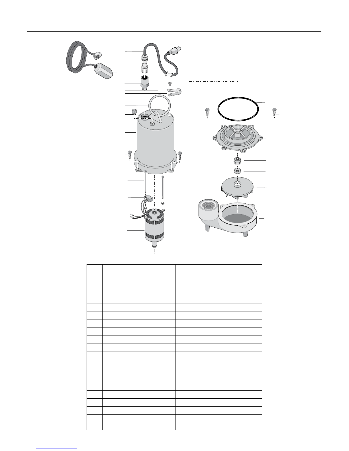
Repair Parts 8
1
2
3
4
5
6
7
14
9
8
9
10
11
12
13
Ref. Description Qty. SHEF42M1 SHEF42A1
Power Cord, 20’
1
Power Cord, 30’ PW117-293-TSU
1
PW117-122-TSE
2 Automatic Float Switch 1 - PS17-109
3 Cord Connector 1 PS17-46P
4 #8-32 x 1/2” Capscrew 1 - U30-539SS
5 Switch Cord Clamp 1 - CC0030-13
6 Handle Ring 1 U97-128
7 1/4” NPT Plug 1 U78-57DT
8 Upper Motor Housing 1 PW18-133
9 #10-32 x 3/4” Capscrew 6 U30-482SS
10 #10-32 x 3-1/8” Capscrew 2 U30-963ZP
11 Capacitor 1 PS18-148
12 Spacer 2 U43-139
13 Motor 1 PW118-145
14 O-Ring 1 U9-339
15 Lower Motor Housing 1 PW18-134
16A Shaft Seal, Stationary Head Assembly 1 U9-379A
16B Shaft Seal, Rotating Mating Ring 1 U9-379C
17 Impeller 1 PW5-16P
18 Volute 1 PW1-16
15
16A
16B
17
18
 Loading...