

Pentair SEP 100 Installation Manual
English
sep 100™ D.e. seperation tank
d.e. filter
INSTALLATION GUIDE / INSTALLATIEHANDLEIDING
BEDIENUNGSANTLEITUNG / GUIDE DE L’INSTALLATION
GUIA DE INSTALACION / GUIDE ALL’INSTALLAZIONE
2
Deutsch
9
Nederlands
16
Français
IMPORTANT SAFETY INSTRUCTIONS READ AND FOLLOW ALL INSTRUCTIONES SAVE THESE INSTRUCTIONS
23
Español Italiano
30
37
WATER SOLUTION G-INSB-SEP (Rev. 08/2012)

Customer Support
HERENTALS, BELGIUM (8:30 A.M. to 4:30 P.M.) CET
Website: www.pentairpooleurope.com
English
E-mail : poolemea@pentair.com
The manufacturer, Pentair, has the right to modify the products without previous notice for as far as their
characteristics are not really changed by this.
© 2012 Pentair. All rights reserved. This document is subject to change without notice.
Trademarks and disclaimers: High Flo™, SEP 100™ and Pentair ® are trademarks and/or registered
trademarks of Pentair and/or its afliated companies in the United States and/or other counties.
Warranty conditions: please visit our website www.pentairpooleurope.com
IMPORTANT SAFETY PRECAUTIONS
THESE OPERATING INSTRUCTIONS CONTAIN IMPORTANT INFORMATION
ON THE SAFE, PROPER AND ECONOMICAL OPERATION OF THIS SWIMMING
POOL APPLIANCE. STRICT OBSERVATION OF THE OPERATING INSTRUCTIONS
WILL HELP TO AVOID DANGERS, REDUCE REPAIR COSTS, SHUTDOWN TIMES
AND INCREASE THE RELIABILITY AND WORKING LIFE OF THE PRODUCT.
2
Section 1.
SEPARATION
TANK
SEPARATION TANK INSTALLATION
A. GENERAL INFORMATION
1. The separation tank should be mounted on a level concrete slab. Position the tank so that the instructions,
warnings and pressure gauge are visible to the operator. Also, position the
separation tank so that the piping connections, control valve and drain port
are convenient and accessible for servicing and winterizing.
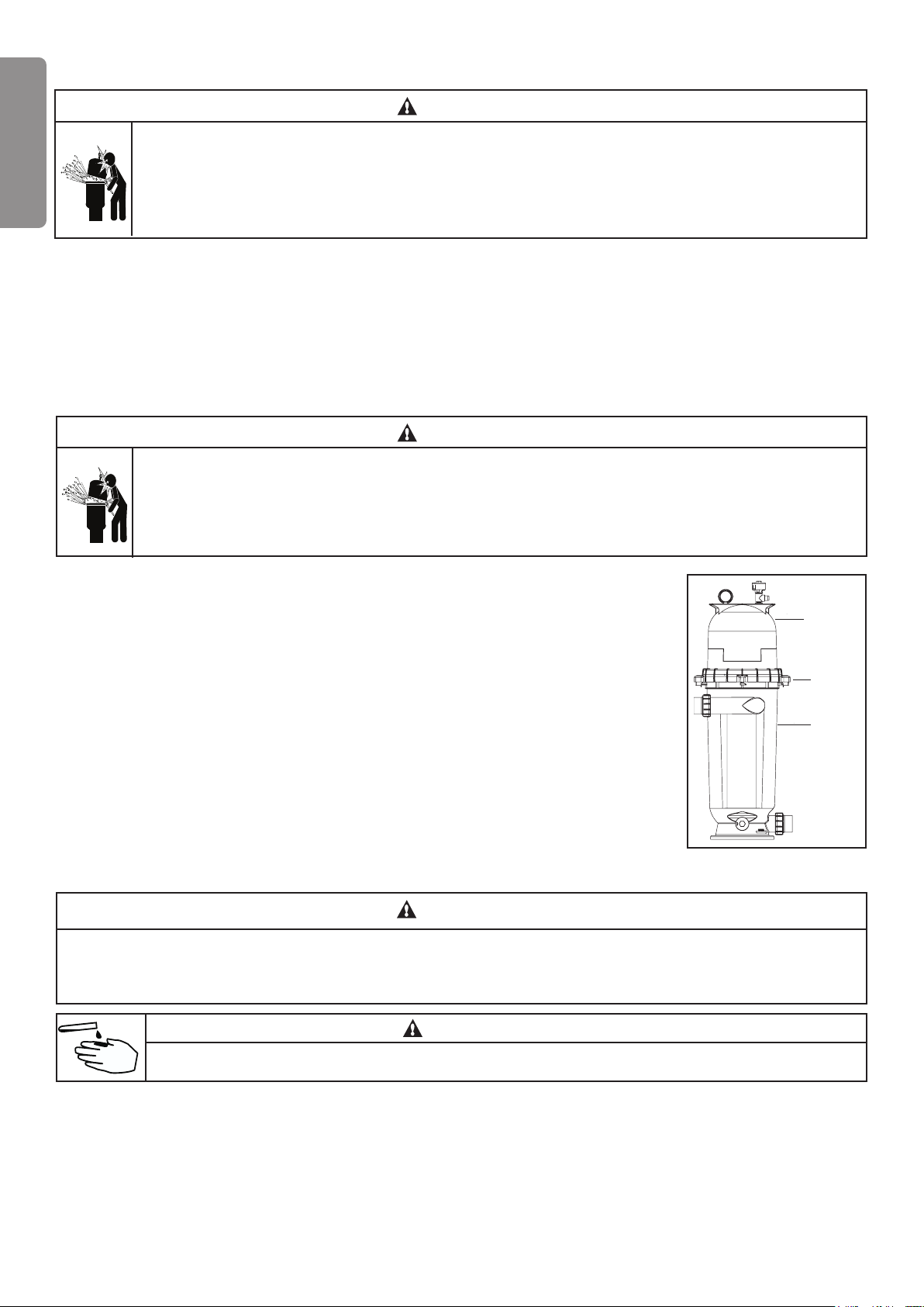
2. Separation tanks are designed to work primarily with diatomaceous earth
(D.E.) swimming pool or spa lters. Their purpose is to separate the D.E. and
dirt from lter efuent during the backwash cycle. The separation process
should produce water out of the separation tank suitable for return back to
the pool or disposal into city storm drain systems. The separation process
uses a large cloth “lter” bag to literally lter out the D.E. and its entrapped
dirt particles. During backwashing of a D.E. lter, a valve is used to reverse
the normal ow through the lter. The reverse ow dislodges the D.E. cake
from the lter and ushes it into the top of the lter bag. The D.E. and dirt are captured in the bag and clean
water passes through and exits from the tank bottom (outlet). After backwashing the lter, the separation tank
needs to be opened and the bag cleaned before another backwashing cycle.
3. Install electrical controls (e.g., on/off switches, timers control systems, etc.) at least 1.5 meter from the tank,
with enough room to stand clear of the tank during system start up.
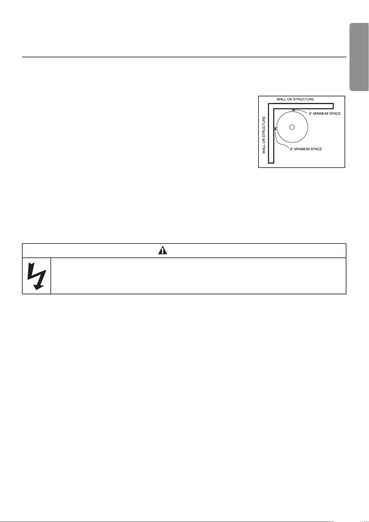
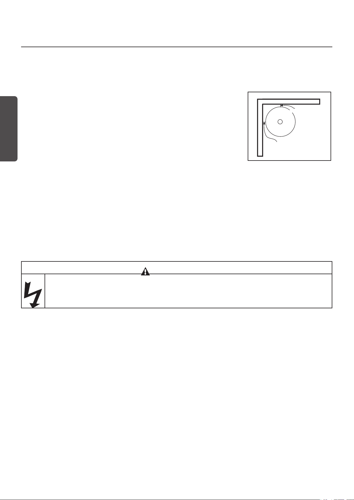
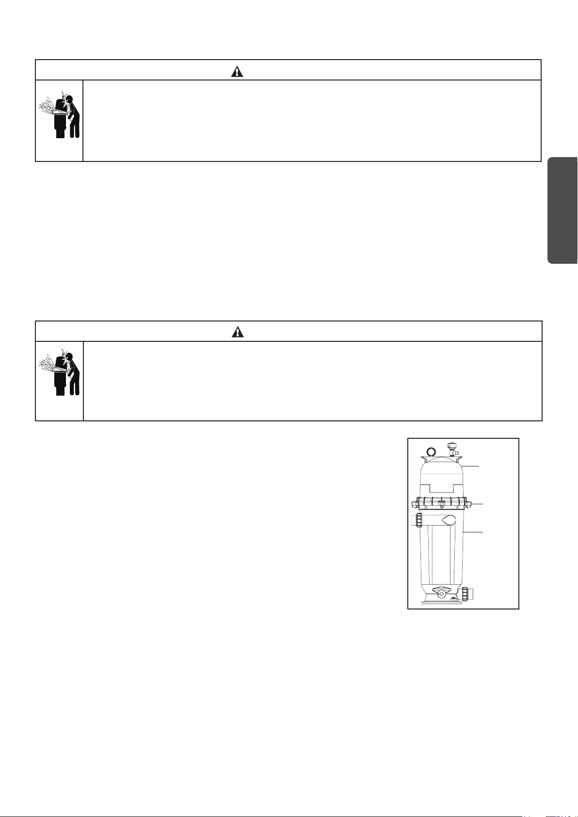
4. Provide sufcient clearance around the tank to permit visual verication that the clamp is properly installed,
see Figure 1.
5. Provide sufcient space above the lter to remove the lter lid for cleaning and servicing.
Figure 1.
English
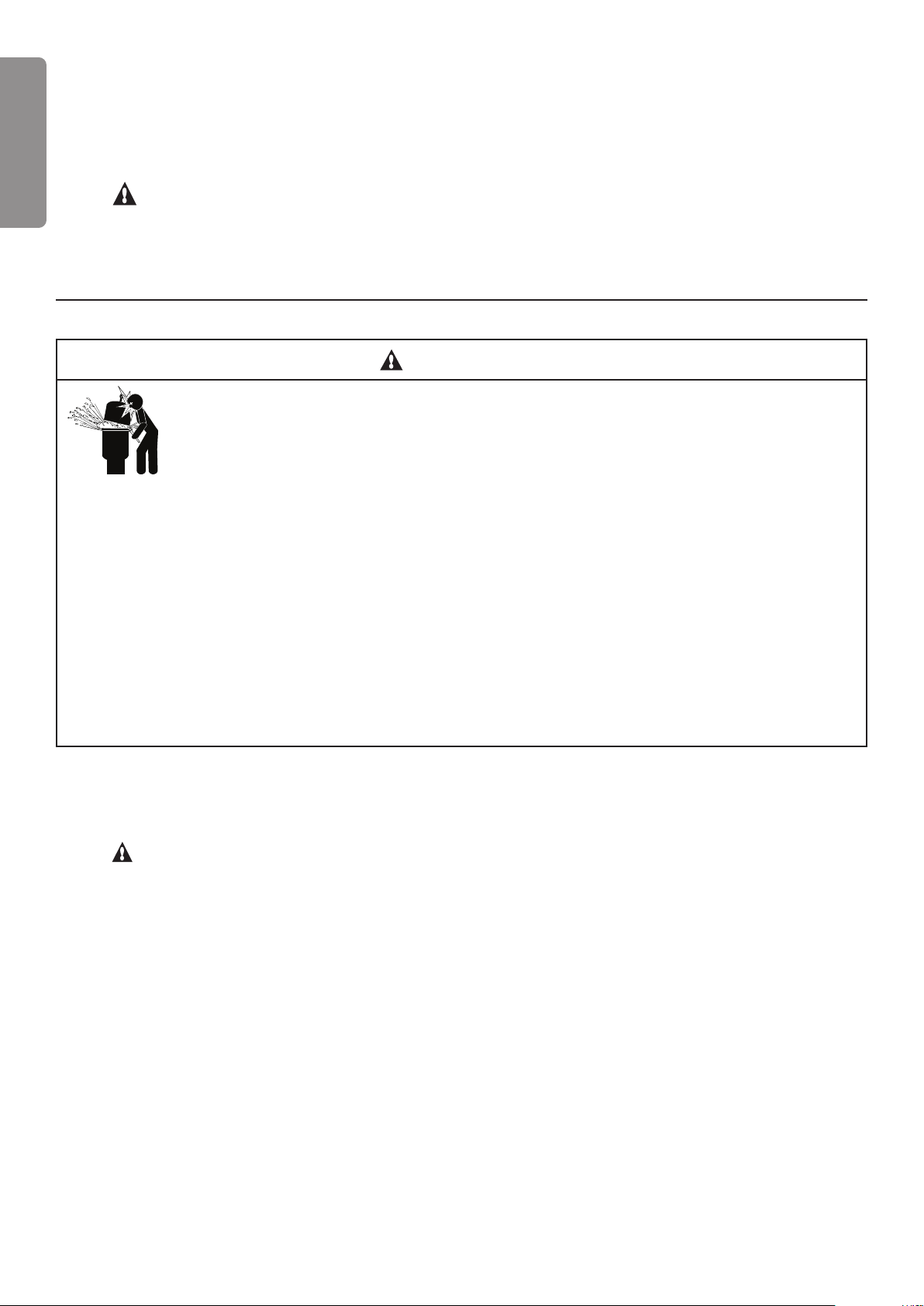
WARNING
Risk of electrical shock or electrocution. Position the separation tank and High Flow™ manual air relief
valve to safely direct water drainage and purged air or water. Water discharged from an improperly
positioned tank or valve can create an electrical hazard that can cause severe personal injury as well as
damage property.
6. When installing the High Flow™ manual air relief valve use the O-ring only, there is no need for thread sealing
compounds. Position the lter to safely direct water drainage. Rotate the valve to safely direct purged air or
water. Water discharged from an improperly positioned lter or valve can create an electrical hazard as well as
damage property.
7. Make all plumbing connections in accordance with local plumbing and building codes. Plumbing connections
are provided with an O-ring seal. Use only a silicone base lubricant on the O-rings. Do not use pipe joint
compound, glue or solvent on the bulkhead connections.
8. The base of the separation tank is provided with four (4) mounting bosses for the purpose of anchoring the
tank to the concrete.
9. The maximum working pressure of the separation tank is 50 psi. Never subject the separation tank to
pressure in excess of this amount, even when conducting hydrostatic pressure tests. Pressures above 50 psi
can cause the lid to be blown off, which can result in severe injury, death or property damage.
When performing hydrostatic pressure tests or when testing for external leaks of the completed ltration and
plumbing system, ensure that the Maximum Pressure that the ltration system will be subjected to DOES NOT
EXCEED THE MAXIMUM WORKING PRESSURE OF ANY OF THE COMPONENTS CONTAINED WITHIN
THE SYSTEM. In most cases, the maximum pressure will be stated on each component of the system.
If doubt exists as to the pressure to which the system will be subjected, install an ASME approved automatic
Pressure Relief or Pressure Regulator in the circulation system for the lowest working pressure of any of the
components in the system.
3
B. SEPARATION TANK INSTALLATION
1. If the separation tank is plumbed to return water back to the pool, a by-pass valve must be used. This valve
must be closed when not backwashing through the separation tank so that the separation tank is not under
English
pressure when in the normal lter mode.
2. WARNING! If the separation tank is plumbed to return water to waste, a positive shut off valve is NOT
recommended in the line from the separation tank. If the system is operated with such a valve closed, the
pressure in the entire system would go abnormally high and could present an explosive situation. Additionally,
running the system with no ow will seriously damage the equipment through heat build-up.
Section 2.
SEPARATION TANK OPERATION
THE SEPARATION TANK OPERATES UNDER HIGH PRESSURE. WHEN ANY PART OF THE
CIRCULATING SYSTEM (e.g., LOCK RING, PUMP, FILTER, VALVES, ETC.) IS SERVICED, AIR
CAN ENTER THE SYSTEM AND BECOME PRESSURIZED. PRESSURIZED AIR CAN CAUSE
THE LID TO BLOW OFF WHICH CAN RESULT IN SEVERE INJURY, DEATH, OR PROPERTY
DAMAGE. TO AVOID THIS POTENTIAL HAZARD, FOLLOW THESE INSTRUCTIONS
1. BEFORE REPOSITIONING VALVES AND BEFORE BEGINNING THE ASSEMBLY, DISASSEMBLY, OR
ADJUSTMENT OF THE LOCK RING OR ANY OTHER SERVICE OF THE CIRCULATING SYSTEM: (A)
TURN THE PUMP OFF AND SHUT OFF ANY AUTOMATIC CONTROLS TO ASSURE THE SYSTEM IS NOT
INADVERTENTLY STARTED DURING THE SERVICING; (B) OPEN AIR RELIEF VALVE; AND (C) WAIT
UNTIL ALL PRESSURE IS RELIEVED -PRESSURE GAUGE MUST READ ZERO (0).
2. WHENEVER INSTALLING THE LOCK RING, FOLLOW THE FILTER LOCK RING INSTALLATION
INSTRUCTIONS EXACTLY.
3. ONCE SERVICE ON THE CIRCULATING SYSTEM IS COMPLETE, FOLLOW SYSTEM RESTART
INSTRUCTIONS EXACTLY.
4. MAINTAIN CIRCULATION SYSTEM PROPERLY. REPLACE WORN OR DAMAGED PARTS IMMEDIATELY
(e.g., lock ring, pressure gauge, relief valve, O-rings, etc.)
5. BE SURE THAT THE SEPARATION TANK IS PROPERLY MOUNTED AND POSITIONED ACCORDING TO
THE INSTRUCTIONS PROVIDED.
WARNING
A. GENERAL INFORMATION
1. The separation tank operates under pressure. When the lock ring is installed properly and operated without air
in the water system, the separation tank will operate in a safe manner.
2. WARNING! The maximum working pressure of the sepataion tank is 3.5 BAR (50 psi). Never subject the
tank to pressure in excess of this amount - even when conducting hydrostatic pressure tests. Pressures above
3.5 BAR (50 psi) can cause lid separation, which can result in serious injury, death or property damage.
When performing hydrostatic pressure tests or when testing for external leaks of the completed ltration and
plumbing system, ensure that the Maximum Pressure that the ltration system will be subjected to DOES NOT
EXCEED THE MAXIMUM WORKING PRESSURE OF ANY OF THE COMPONENTS CONTAINED WITHIN
THE SYSTEM. In most cases, the maximum pressure will be stated on each component of the system.
If doubt exists as to the pressure to which the system will be subjected, install an ASME approved automatic
Pressure Relief or Pressure Regulator in the circulation system for the lowest working pressure of any of the
components in the system.
3. The pressure gauge is the primary indicator of how the separation tank is operating. Maintain your pressure
gauge in good working order.
4
WARNING
Your separation tank is a piece of machinery, do not tamper with it, attempt to disassemble it or
otherwise adjust it unless you fully understand it’s operation. Serious injury or death can occur if the
equipment is improperly handled. Consult a pool service professional for maintenance and service
assistance.
4. Clean your lter when pressure reads between 0.5 - 0.8 BAR (8-10 psi) higher than the original starting
pressure. Your lter pressure reading will increase as it removes dirt from your pool. However, this buildup of
pressure will vary due to different bathing loads, temperature, weather conditions, etc.
MY ORIGINAL STARTING PRESSURE IS ___________ BAR or PSI
I SHOULD CLEAN THE FILTER CARTRIDGES AT __________ BAR or PSI
5. Change valve positions
• if using a multi-port valve, set to backwash position.
• if using a two position valve, reposition the valve to backwash position.
• if separation tank is plumbed to return water to pool, open by-pass valve.
• open manual air bleed on top of separation tank.
6. Stand clear of lter and separation tank. Start pump, this will circulate water backwards through the lter
and ush D.E. cake and contaminants into the separation tank. Close the manual air bleed on the top of the
separation tank when a steady stream of water emerges.
7. When the backwashing action is complete, (see your lter operating instructions), stop the pump.
English
8. Change valve positions;
• set lter valve to lter position.
• close separation tank by-pass valve.
• open manual air bleed on top of separation tank..
9. Disassemble and clean your separation tank following the instructions given herein.
B. LOCK RING INSTALLATION INSTRUCTIONS
These instructions MUST BE FOLLOWED EXACTLY to prevent the lid from blowing off during system restart
or later operation.
1. Perform the following steps before working on any part of the circulating system (e.g., lock ring, pump, lter,
valves, etc.).
a. Turn the pump off and shut off any automatic controls to ensure that the system is not inadvertently
started during servicing.
b. Open the High Flow™ manual air relief valve.
c. Wait until all pressure is relieved. Never attempt to assemble, disassemble or adjust the lter lock
ring while there is any pressure in the tank.
5
THE TANK OPERATES UNDER HIGH PRESSURE. WHEN ANY PART OF THE CIRCULATING
SYSTEM (e.g., LOCK RING, PUMP, FILTER, VALVES, ETC.) IS SERVICED, AIR CAN ENTER THE
English
2. Be certain the O-ring is in position in the lower tank half. Place the lter lid over the lower tank half, making
3. Place lock ring over the tank lid, and centering the lock ring on the threads of the tank body. Turn the lock
4. Follow the System Restart Instructions in Section C.
SYSTEM AND BECOME PRESSURIZED. PRESSURIZED AIR CAN CAUSE THE LID TO BE BLOWN
OFF WHICH CAN RESULT IN SEVERE INJURY, DEATH, OR PROPERTY DAMAGE. TO AVOID THIS
POTENTIAL HAZARD, FOLLOW THESE INSTRUCTIONS.
sure it is fully and rmly seated on the tank half, see Figure 2.
ring clockwise until the safety latches click and the lock ring hits the stops on the body. DO NOT ATTEMPT
TO OVER-TIGHTEN THE LOCK RING AFTER LOCK RING HAS HIT THE STOPS ON THE BODY.
C. SYSTEM RESTART INSTRUCTIONS
THE TANK SEPARATION OPERATES UNDER HIGH PRESSURE. WHEN ANY PART OF THE
CIRCULATING SYSTEM (e.g., LOCK RING, PUMP, FILTER, VALVES, ETC.) IS SERVICED, AIR CAN
ENTER THE SYSTEM AND BECOME PRESSURIZED. PRESSURIZED AIR CAN CAUSE THE LID TO
BE BLOWN OFF WHICH CAN RESULT IN SEVERE INJURY, DEATH, OR PROPERTY DAMAGE. TO
AVOID THIS POTENTIAL HAZARD, FOLLOW THESE INSTRUCTIONS.
WARNING
WARNING
1. Open the High Flow™ manual air relief valve until it snaps into the full open
position (this only requires a quarter turn counterclockwise). Opening this
valve rapidly releases air trapped in the tank.
2. Stand clear of the tank, then start the pump.
3. Close the High Flow™ manual air relief valve after a steady stream of water
appears.
4. The system is not working properly if either of the following conditions occur.
a. A solid stream of water does not appear within 30 seconds, after the
pump’s inlet basket lls with water.
b. The pressure gauge indicates pressure before water outow appears.
If either condition exists, shut off the pump immediately, open valves in the
water return line to relieve pressure, and clean the air relief valve, see Section F.
Cleaning the High Flow™ manual air relief valve.
D. CLEANING THE SEPARATION TANK
WARNING
The following information should be read carefully since it outlines the proper manner of care and
operation for your lter system. As a result of following these instructions and taking the necessary
preventative care, you can expect maximum efciency and life from your lter system.
Filter
Tank
Top
Lock
Ring
Filter
Tank
Body
Figure 2
CAUTION
Please heed all manufacturers’ posted instructions, warnings and cautions when using Baquacil®.
6
1. Turn the pump off, shut off any automatic controls to ensure that the system is not inadvertently started during
servicing.
2. Open the lter High Flow™ manual air relief valve, (and the waste drain valve, or cap, if your system has
one).
3. Remove hair and lint strainer pot lid and clean basket. Replace basket and secure lid.
4. Open the drain valve and wait for the water to drain from the separation tank before removing the bag
containing D.E. and contaminants.
5. Remove locking ring by depressing safety latches on both sides of ring and rotate counterclockwise, then
remove tank lid.
6. Remove the separation bag by pulling straight up on the bag handle loop.
7. Dispose of waste in trash and rinse bag clean. Inspect bag for holes - replace if necessary.
8. Clean and remove debris from inside the lter tank and from the O-ring and O-ring groove on the tankbody.
9. Install the clean bag into the tank assembly making sure it is seated onto the separation tank ring.
10. Replace the tank lid onto the tank body making sure it is fully and rmly seated on the tank body.
11. Place lock ring over tank lid, and centering the lock ring on the threads of the tank body, turn the lock ring
clockwise until the safety latches click and the lock ring hits the stops on the body. DO NOT ATTEMPT TO
OVER-TIGHTEN THE LOCK RING AFTER LOCK RING HAS HIT THE STOPS ON THE BODY.
English
NOTE
Any time the separation tank is opened, and/or separation bag is removed, be sure to generously coat the O-
ring with silicone lubricant before reassembling the unit. DO NOT USE PETROLEUM BASED LUBRICANTS
BECAUSE THEY HAVE A DETERIORATING EFFECT ON RUBBER.
12. Replace drain cap and reinstall High Flow™ manual air relief valve drain hose if used.
E. CLEANING THE HIGH FLOW™ MANUAL AIR RELIEF
VALVE
1. Turn the pump off and shut off any automatic controls to ensure
that the system is not inadvertently started during servicing.
2. OPEN THE HIGH FLOW™ MANUAL AIR RELIEF VALVE UNTIL
IT SNAPS INTO THE FULL OPEN POSITION, THEN WAIT
UNTIL ALL PRESSURE IS RELIEVED.
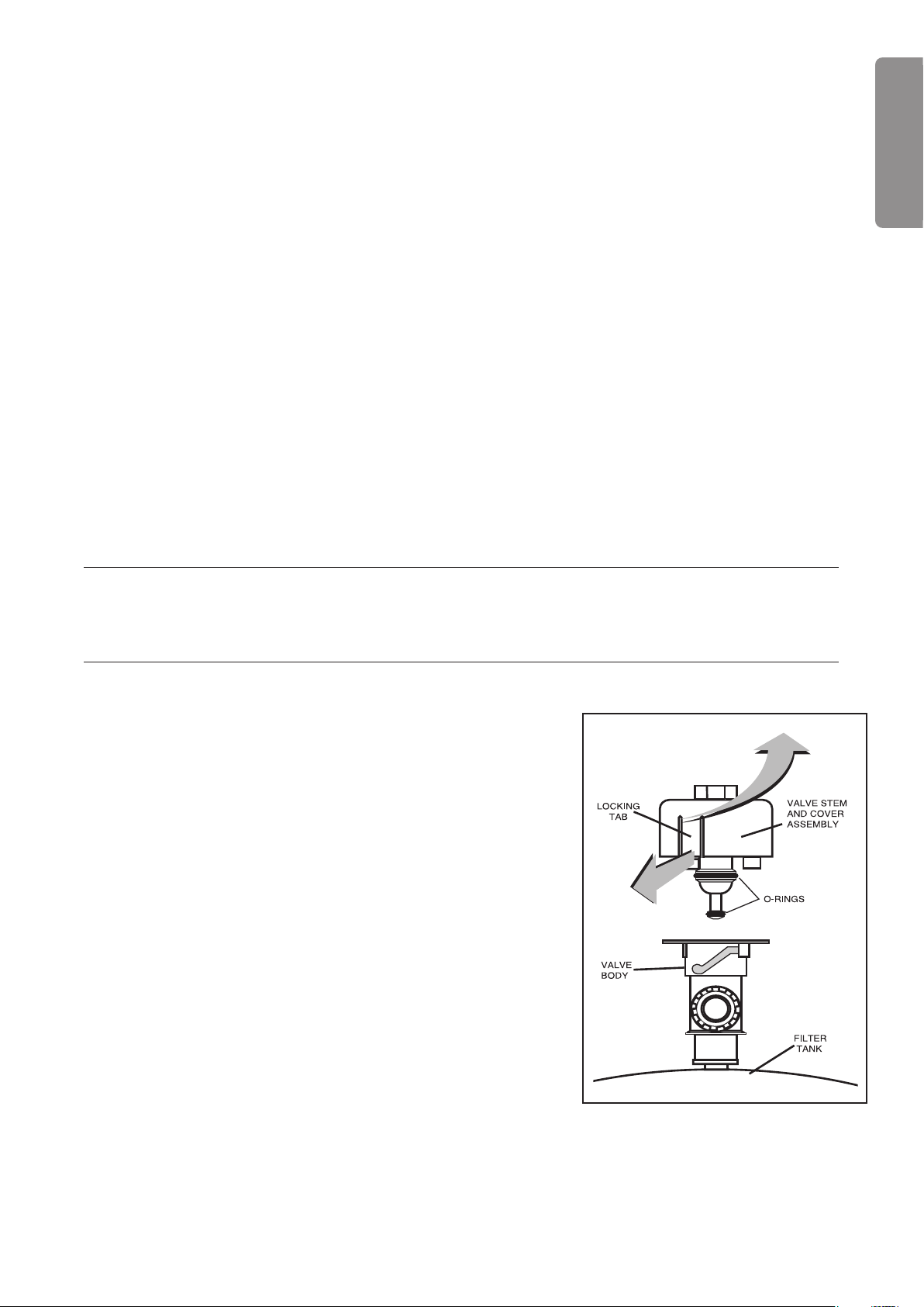
3. With the relief valve attached to the lter tank, pull out the locking
tabs and remove the valve stem and cover assembly with a
counterclockwise and lifting motion, see Figure 3.
4. Clean debris from the valve stem and body. Verify that the lter
tank’s air passage is open by inserting a 5/16 in. drill bit through
the valve body. Verify that the O-ring are in good condition, properly
positioned, and lubricated with a silicone base lubricant.
5. Reinstall the valve stem and cover assembly with a downward and
clockwise motion until it snaps into position.
Figure 3.
7

Section 3.
TROUBLESHOOTING
English
A. Air entering your lter is dangerous and can cause the lid to blow off. Correct any conditions in your ltration
system that allow air to enter the system.
1. Some common ways to identify air entering the system:
a. Low water level in pool or spa - skimmer is starving for water with pump running. Add water to pool or
spa.
b. Air bubbles or low water level in pump hair and lint pot are caused by; low water level, clogged skim-
mer basket, split suction cleaner hose, leak in pump hair and lint pot lid, or leak in pump suction line.
c. Air bubbles coming out of water return lines into pool or spa with pump running, see items 1.a and 1.b
of this section.
d. Air is discharged from the air relief valve on top of the lter when the valve is opened with the pump
running, see items 1.a and 1.b of this section, above.
B. If the D.E. is returning back to the pool upon backwashing, check to make sure the bag is seated properly on
the separation bag ring. Also check the bag to see if it is torn or missing. If the bag is torn, a replacement is
needed.
C. The pressure gauge is an important part of the separation tank. It is your primary indicator of how the system
is operating. Maintain your pressure gauge in good working order. Check the operation of your pressure gauge
in the following manner:
1. The pressure gauge should go to zero (0) when the system is turned off and pressure is relieved.
2. The pressure gauge should indicate pressure when the system is operating.
3. The pressure gauge should be readable and not damaged in any way.
4. Replace the pressure gauge if it is not meeting the requirements of items D.1 through D.2 of this section,
above.
LIMITED WARRANTY : 2 YEARS
Further details : www.pentairpooleurope.com
8

Kundendienst
HERENTALS, BELGIEN (8:30h - 16:30h) MEZ
Webseite: www.pentairpooleurope.com
E-mail : poolemea@pentair.com
Der Hersteller, Pentair, hat das Recht, die Produkte ohne vorherige Mitteilung zu ändern, sofern ihre
Eigenschaften dadurch nicht verändert werden
© 2012 Pentair. Alle Rechte vorbehalten. Änderungen vorbehalten.
Marken und Haftungsausschluss: High Flo XF™, SEP 100™ und Pentair® sind Marken und/oder eingetragene
Marken von Pentair und/oder ihren verbundenen Unternehmen in den Vereinigten Staaten und/oder anderen
Ländern.
Gewährleistungsbedingungen: Bitte besuchen Sie unsere Webseite www.pentairpooleurope.com
.
Deutsch
WICHTIGE SICHERHEITSHINWEISE
DIE BETRIEBSANLEITUNG ENTHÄLT WICHTIGE HINWEISE, UM DIESE APPARATE
SICHERSACHGERECHT UND WIRSCHAFTLICH ZU BETRIEBEN. IHRE BEACHTUNG
HILFT GEFAHREN ZU VERMEIDEN, REPARATURKOSTEN UND AUSFALLZEITEN
ZU VERMINDERN UND DIE ZUVER-LÄSSIKETI UND LEBENSDAUER ZU ERHÖREN.
9
Abschnitt 1.
SEPARATION
TANK
INSTALLATION DES ABSCHEIDEBEHÄLTERS
A. ALLGEMEINE INFORMATIONEN
1. Der Abscheidebehälter sollte auf eine ebene Betonplatte montiert werden. Positionieren Sie den Behälter, so
dass die Anweisungen, Warnungen und Druckanzeige für den Bediener sichtbar sind. Beachten Sie bei der
Positionierung des Abscheidebehälters auch, dass die Leitungsanschlüsse,
Steuerventile und der Abussanschluss für eine optimale Wartung und
Einwinterung zugänglich sind.
2. Die Abscheidebehälter wurden entwickelt, um hauptsächlich mit Kieselerde-
Filtern in Pools oder Whirlpools zu arbeiten. Ihre Aufgabe ist die Abscheidung
von Kieselerde und Schmutz aus dem Filterabwasser beim Rückspülzyklus.
Beim Abscheideprozess muss Wasser entstehen, das wieder in den Pool
Deutsch
oder das Regenwasserableitungssystem der Gemeinde geleitet werden kann.
Der Abscheideprozess nutzt eine große Stoffltertasche, um die Kieselerde
und mitgeführte Schmutzpartikel herauszultern. Bei der Rückspülung eines
Kieselerde-Filters wird ein Ventil eingesetzt, um den normalen Fluss durch
den Filter umzukehren. Der umgekehrte Fluss löst die Ansammlung der Kieselerde vom Filter und spült diese
oben in die Filtertasche. Die Kieselerde und der Schmutz werden in der Tasche gesammelt und sauberes
Wasser ießt durch den Filter und verlässt den Behälter an der unteren Auslassöffnung.
Nach der Rückspülung des Filters muss der Behälter vor dem nächsten
Rückspülzyklus geöffnet und die Filtertasche gereinigt werden.
3. Elektrische Steuerelemente (z.B.: Ein/Aus-Schalter, Zeitschaltsysteme, etc.) sind mindestens mit einem
Abstand von 1,5 Meter zum Behälter zu installieren und es muss ausreichend Platz vorhanden sein, damit der
Behälter beim Systemstart nicht berührt wird.
4. Sorgen Sie für ausreichend Abstand um den Behälter, damit per Sichtprüfung bestätigt werden kann, dass die
Klemme ordnungsgemäß installiert ist, siehe Abbildung 1.
5. Sorgen Sie für ausreichend Platz über dem Filter, um den Filterdeckel für die Reinigung und Wartung
entfernen zu können.
WAND ODER GEBÄUDE
ABSCHEIDE-
BEHÄLTER
WAND ODER GEBÄUDE
Abbildung 1.
MINDESTABSTAND 15 CM
MINDESTABSTAND
15 CM
WARNUNG
10
Gefahr durch elektrischen Strom und Stromschlag. Positionieren Sie den Abscheidebehälter und das manuelle
High Flow™ Entlüftungsventil entsprechend, um den Wasserabuss und die Spülluft sowie das Spülwasser sicher
abzuführen. Der Wasserablass eines unangemessen positionierten Behälters oder Ventils kann Stromschläge
verursachen, die zu Personenschäden oder Sachschäden führen können.
6. Bei der Installation des manuellen High Flow™ Entlüftungsventils dürfen nur O-Ringe verwendet werden. Es
ist nicht erforderlich, Gewindedichtmittel zu verwenden. Positionieren Sie den Filter, um den Wasserablass
sicher abzuführen. Rotieren Sie das Ventil, um die Spülluft oder das Spülwasser sicher abzuführen. Der
Wasserablass eines unangemessen positionierten Filters oder Ventils kann Stromschläge oder Sachschäden
verursachen.
7. Alle Rohrleitungsanschlüsse sind entsprechend der örtlichen Klempner- und Gebäuderichtlinien
auszuführen. Rohrleitungsanschlüsse werden mit einer O-Ring-Dichtung versehen. Verwenden Sie bei
den O-Ringen nur Silikon-Schmiermittel. Verwenden Sie keine Dichtmasse, Kleber oder Lösemittel an den
Trennwandanschlüssen.
8. Der Abscheidebehälter verfügt an der Unterseite über vier (4) Montageaufnahmen zur Befestigung des
Behälters auf dem Beton.
9. Der maximale Arbeitsdruck des Abscheidebehälters beträgt 50psi. Lassen Sie den Abscheidebehälter niemals
über diesem Druck arbeiten, auch nicht bei der Durchführung von hydrostatischen Drucktests. Bei einem
Druck über 50psi kann der Deckel abgerissen werden und zu schwerwiegenden Verletzungen, zum Tod oder
zu Sachschäden führen.
Bei der Durchführung von hydrostatischen Tests oder wenn auf externe Undichtigkeiten der kompletten Filtereinheit und des Rohrleistungssystems geprüft wird, ist sicherzustellen, dass der maximale, auf die Filtereinheit
wirkende Druck, NICHT DEN MAXIMALEN ARBEITSDRUCK DER BAUTEILE IM SYSTEM ÜBERSCHREITET.
In den meisten Fällen wird der maximale Druck auf jedem Bauteil des Systems angegeben.
Sollte nicht klar sein, welchem Druck das System ausgesetzt wird, müssen Sie einen ASME-zertizierten auto-
B. INSTALLATION DES ABSCHEIDEBEHÄLTERS
1. Wenn der Abscheidebehälter über ein Rohrleistungssystem verfügt, um das Rückusswasser wieder in den
Pool zu leiten, muss ein Bypass-Ventil verwendet werden. Dieses Ventil muss geschlossen werden, wenn
keine Rückspülung durch den Abscheidebehälter durchgeführt wird, so dass der Abscheidebehälter im
normalen Filtermodus nicht unter Druck steht.
2.
ACHTUNG! Wenn der Abscheidebehälter über ein Rohrleistungssystem verfügt, um das Rückusswasser
in das Abwassersystem zu leiten, wird NICHT empfohlen, dass die Leitung des Abscheidebehälters ein
formschlüssiges Absperrventil besitzt. Wenn das System betrieben wird, wenn solch ein Ventil geschlossen
ist, würde sich der Druck im gesamten System abnormal erhöhen und einen explosiven Zustand erreichen.
Darüber hinaus würde ein Betrieb des Systems ohne Wasserdurchuss zu einem Wärmestau und somit zu
Schäden an der Anlage führen.
Abschnitt 2.
BETRIEB DES ABSCHEIDEBEHÄLTERS
WARNUNG
DER ABSCHEIDEBEHÄLTER ARBEITET BEI HOHEM DRUCK. WENN EIN TEIL DES UMLAUFSYSTEMS
(z.B. SICHERUNGSRING, PUMPE, FILTER, VENTILE, USW.) GEWARTET WIRD, KANN LUFT IN DAS
SYSTEM GELANGEN UND ZU EINEM DRUCKAUFBAU FÜHREN. DER DRUCK KANN DAZU FÜHREN,
DASS DER DECKEL ABGERISSEN WIRD, WAS ZU SCHWEREN VERLETZUNGEN, TOD ODER
SACHSCHÄDEN FÜHREN KANN. UM DIESE POTENZIELLE GEFAHR ZU VERMEIDEN, BEFOLGEN SIE
DIESE ANWEISUNGEN.
Deutsch
1. VOR DER NEUPOSITIONIERUNG DER VENTILE ODER VOR BEGINN DER MONTAGE, DEMONTAGE
ODER EINSTELLUNG DES SICHERUNGSRINGS ODER JEGLICHE SONSTIGE WARTUNGSARBEITEN
AM UMLAUFSYSTEM: (A) MUSS DIE PUMPE UND ALLE AUTOMATISCHEN STEUERFUNKTIONEN
AUSGESCHALTET WERDEN, UM SICHERZUSTELLEN, DASS DAS SYSTEM WÄHREND DER
WARTUNG NICHT UNGEWOLLT STARTET; (B) IST DAS ENTLÜFTUNGSVENTIL ZU ÖFFNEN;
UND (C) MUSS GEWARTET WERDEN, BIS DER GESAMTE DRUCK ABGELASSEN WURDE – DIE
DRUCKANZEIGE MUSS NULL (0) ANZEIGEN.
2. BEI DER INSTALLATION DES SICHERUNGSRINGS IST DIE EINBAUANWEISUNG DES
SICHERUNGSRINGS FÜR DEN FILTER GENAU ZU BEACHTEN.
3. SOBALD DIE WARTUNG AM UMLAUFSYSTEM ABGESCHLOSSEN IST, IST DIE ANWEISUNG FÜR DEN
NEUSTART DES SYSTEMS GENAU ZU BEACHTEN.
4. DAS UMLAUFSYSTEM IST ORDNUNGSGEMÄSS ZU WARTEN. VERSCHLISSENE ODER
BESCHÄDIGTE TEILE SIND SOFORT AUSZUTAUSCHEN (z.B. Sicherungsring, Druckanzeige,
Ablassventil, O-Ringe, etc.)
5. STELLEN SIE SICHER, DASS DER ABSCHEIDEBEHÄLTER GEMÄSS DEN ANWEISUNGEN
ORDNUNGSGEMÄSS MONTIERT UND POSITIONIERT IST.
A. ALLGEMEINE INFORMATIONEN
1. Der Abscheidebehälter arbeitet unter Druck. Wenn der Sicherungsring ordnungsgemäß installiert wurde und
keine Luft im Wassersystem vorhanden ist, arbeitet der Abscheidebehälter sicher.
2. ACHTUNG! Der maximale Arbeitsdruck des Abscheidebehälters beträgt 3,5 bar (50psi). Lassen Sie
den Behälter niemals über diesem Druck arbeiten, auch nicht bei der Durchführung von hydrostatischen
Drucktests. Bei einem Druck über 3,5bar (50psi) kann der Deckel abgerissen werden und zu
schwerwiegenden Verletzungen, zum Tod oder zu Sachschäden führen.
Bei der Durchführung von hydrostatischen Tests oder wenn auf externe Undichtigkeiten der kompletten Filtereinheit und des Rohrleistungssystems geprüft wird, ist sicherzustellen, dass der maximale, auf die Filtereinheit
wirkende Druck, NICHT DEN MAXIMALEN ARBEITSDRUCK DER BAUTEILE IM SYSTEM ÜBERSCHREITET.
In den meisten Fällen wird der maximale Druck auf jedem Bauteil des Systems angegeben.
Sollte nicht klar sein, welchem Druck das System ausgesetzt wird, müssen Sie einen ASME-zertizierten automatischen Druckbegrenzer oder Druckregler in das Umlaufsystem einbauen, so dass das Bauteil im System mit
dem niedrigsten Arbeitsdruck geschützt ist.
3. Die Druckanzeige ist der wichtigste Indikator hinsichtlich des Betriebs des Abscheidebehälters. Halten Sie den
11
Druckanzeiger in einwandfreiem Zustand.
4. Reinigen Sie Ihren Filter, wenn der Druck zwischen 0,5 - 0,8 bar (8 - 10 psi) höher liegt, als der ursprüngliche
Startdruck. Der Druck in Ihrem Filter steigt mit der Zeit an, wenn Schmutz aus Ihrem Pool herausgeltert wird.
Diese Schmutzansammlung variiert jedoch abhängig von der Nutzung des Schwimmbads, der Temperatur,
den Wetterbedingungen, etc.
MEIN URSPRÜNGLICHER STARTDRUCK BETRÄGT ___________ BAR oder PSI
ICH SOLLTE DIE FILTERKARTUSCHE BEI EINEM DRUCK VON __________ BAR oder
Deutsch
5. Veränderung der Ventilpositionen
• Wenn ein Mehrwegeventil verwendet wird, das Ventil auf die Rückspülposition stellen.
• Wenn ein Zweiwegeventil verwendet wird, das Ventil auf die Rückspülposition stellen.
• Wenn der Abscheidebehälter über ein Rohrleistungssystem verfügt, um das Rückusswasser wieder in
• Das manuelle Entlüftungsventil oben am Abscheidebehälter öffnen.
6. Halten Sie etwas Abstand zum Filter und dem Abscheidebehälter. Starten Sie die Pumpe, dadurch wird
Wasser rückwärts durch den Filter geleitet und die Ansammlung der Kieselerde sowie Verschmutzungen in
den Abscheidebehälter gespült. Schließen Sie das manuelle Entlüftungsventil oben am Abscheidebehälter,
wenn ein stetiger Wasseruss austritt.
WARNUNG
Ihre Abscheidebehälter ist eine Maschine; manipulieren Sie das Gerät nicht, versuchen Sie nicht es zu
demontieren oder anderweitig einzustellen, wenn Sie nicht umfassend mit dem Betrieb vertraut sind. Eine
unsachgemäße Nutzung der Anlage kann zu ernsthaften Verletzungen oder zum Tod führen. Nehmen Sie für die
Wartung und Hilfe beim Service Kontakt mit einem Schwimmbadbauer auf.
PSI REINIGEN
den Pool zu leiten, muss das Bypass-Ventil geöffnet werden.
7. Wenn der Rückspülprozess abgeschlossen ist, (siehe Ihre Anweisungen zum Filterbetrieb), stoppen Sie die
Pumpe.
8. Veränderung der Ventilpositionen
• Stellen Sie das Filterventil auf die Filterposition.
• Das Bypass-Ventil des Abscheidebehälters schließen.
• Das manuelle Entlüftungsventil oben am Abscheidebehälter öffnen.
9. Den Abscheidebehälter gemäß den hier genannten, folgenden Anweisungen demontieren und säubern.
B. INSTALLATIONSANWEISUNGEN DES SICHERUNGSRINGS
Diese Anweisungen MÜSSEN GENAU BEFOLGT WERDEN, um zu verhindern, dass der Deckel beim
Systemneustart oder späteren Betrieb abgerissen wird.
1. Führen Sie die folgenden Schritte aus, bevor an Bauteilen des Umlaufsystems (z.B. Sicherungsring, Pumpe,
Filter, Ventile, etc.) gearbeitet wird.
a. Schalten Sie die Pumpe aus und stellen Sie alle automatischen Steuerfunktionen aus, um
sicherzustellen, dass das System während der Wartung nicht ungewollt startet.
b. Öffnen Sie das manuelle High Flow™ Entlüftungsventil.
c. Warten Sie bis der gesamte Druck abgelassen wurde. Versuchen Sie niemals, den Sicherungsring
für den Filter zu montieren, demontieren oder einzustellen, während der Behälter noch unter
Druck steht.
12
WARNUNG
DER BEHÄLTER ARBEITET BEI HOHEM DRUCK. WENN EIN TEIL DES UMLAUFSYSTEMS
(z.B. SICHERUNGSRING, PUMPE, FILTER, VENTILE, USW.) GEWARTET WIRD, KANN LUFT IN DAS
SYSTEM GELANGEN UND ZU EINEM DRUCKAUFBAU FÜHREN. DER DRUCK KANN DAZU FÜHREN, DASS
DER DECKEL ABGERISSEN WIRD, WAS ZU SCHWEREN VERLETZUNGEN, TOD ODER SACHSCHÄDEN
FÜHREN KANN. UM DIESE POTENZIELLE GEFAHR ZU VERMEIDEN, BEFOLGEN SIE DIESE
ANWEISUNGEN.
2. Stellen Sie sicher, dass der O-Ring in der unteren Behälterhälfte in Position ist. Platzieren Sie den Filterdeckel
über die untere Behälterhälfte, wobei darauf zu achten ist, dass er vollständig und fest auf der Behälterhälfte
sitzt, siehe Abbildung 2.
3. Platzieren Sie den Sicherungsring über den Behälterdeckel und richten Sie den Sicherungsring mittig
auf den Gewinden des Behältergehäuses aus. Drehen Sie den Sicherungsring im Uhrzeigersinn bis die
Sicherungslaschen einrasten und der Sicherungsring am Anschlag des Gehäuses anschlägt. VERSUCHEN
SIE NICHT DEN SICHERUNGSRING ZU ÜBERDREHEN, NACHDEM ER DEN ANSCHLAG AM GEHÄUSE
ERREICHT HAT.
4. Beachten Sie die in Abschnitt C beschriebene Anweisung für den Neustart des Systems.
C. ANWEISUNGEN FÜR DEN NEUSTART DES SYSTEMS
WARNUNG
DER ABSCHEIDEBEHÄLTER ARBEITET BEI HOHEM DRUCK. WENN EIN TEIL DES UMLAUF SYSTEMS (z.B.
SICHERUNGSRING, PUMPE, FILTER, VENTILE, USW.) GEWARTET WIRD, KANN LUFT IN DAS SYSTEM
1. Öffnen Sie das manuelle High Flow™ Entlüftungsventil bis dieses
2. Halten Sie einen Abstand zum Behälter ein und starten Sie dann die Pumpe.
3. Schließen Sie das manuelle High Flow™ Entlüftungsventil, wenn ein stetiger
4. Das System arbeitet nicht ordnungsgemäß, wenn eine der folgenden
GELANGEN UND ZU EINEM DRUCKAUFBAU FÜHREN. DER DRUCK KANN DAZU FÜHREN, DASS DER
DECKEL ABGERISSEN WIRD, WAS ZU SCHWEREN VERLETZUNGEN, TOD ODER SACHSCHÄDEN
FÜHREN KANN. UM DIESE POTENZIELLE GEFAHR ZU VERMEIDEN, BEFOLGEN SIE DIESE
ANWEISUNGEN.
vollständig geöffnet ist (hierfür ist nur eine Viertelumdrehung gegen
Uhrzeigersinn erforderlich). Durch das Öffnen des Ventils entweicht die im
Behälter vorhandene Luft schnell.
Wasseruss austritt.
Zustände auftritt.
a. Wenn innerhalb von 30 Sekunden kein stetiger Wasseruss austritt,
nachdem der Zulaufkorb der Pumpe sich mit Wasser gefüllt hat.
a. Wenn die Druckanzeige einen Druck anzeigt, bevor Wasser austritt.
Filter-
behälter
oben
Sicherungsring
Filter-
behältergehäuse
Deutsch
Wenn beide Zustände eintreten, muss sofort die Pumpe ausgeschaltet
werden; die Ventile der Wasserrückussleitung geöffnet werden, um den
Druck entweichen zu lassen; und das Entlüftungsventil gereinigt werden,
siehe Abschnitt F. Reinigung des manuellen High Flow™ Entlüftungsventils.
13
Abbildung 2
D. REINIGUNG DES ABSCHEIDEBEHÄLTERS
WARNUNG
Die folgenden Informationen sollten aufmerksam gelesen werden, da hier die ordnungsgemäße
Pege und der richtige Betrieb Ihres Filtersystems beschrieben wird. Wenn Sie diese Anweisungen
befolgen und das System entsprechend pegen, wird das Filtersystem eine maximale Leistung
erbringen und eine lange Nutzungsdauer aufweisen.
VORSICHT
Bitte befolgen Sie alle angegebenen Anweisungen sowie Warnungs- und Achtungsmeldungen des
Herstellers bei der Verwendung von Baquacil®.
Deutsch
1. Schalten Sie die Pumpe aus und stellen Sie alle automatischen Steuerfunktionen aus, um sicherzustellen,
dass das System während der Wartung nicht ungewollt startet.
2. Öffnen Sie das manuelle High Flow™ Entlüftungsventil (und das Abussventil, oder die Kappe, falls Ihr
System damit ausgestattet ist).
3. Entfernen Sie den Deckel vom Haar- und Fusselsieb und reinigen Sie den Korb. Setzen Sie den Korb wieder
ein und befestigen Sie den Deckel.
4. Öffnen Sie das Abussventil und warten Sie bis das gesamte Wasser aus dem Abscheidebehälter abgelassen
wurde, bevor die Tasche mit der Kieselerde und dem Schmutz entnommen wird.
5. Entfernen Sie den Sicherungsring, indem Sie die Sicherungslaschen auf beiden Seiten des Rings
niederdrücken und den Ring gegen den Uhrzeigersinn drehen. Nehmen Sie anschließend den Behälterdeckel
ab.
6. Entnehmen Sie die Abscheidetasche, indem Sie den Schlaufengriff der Tasche gerade nach oben ziehen.
7. Entsorgen Sie den Abfall im Restmüll und spülen Sie die Tasche aus. Überprüfen Sie die Tasche auf Löcher -
ggf. ersetzen.
8. Säubern Sie den Filterbehälter und entfernen Sie Verschmutzungen im Inneren des Filterbehälters und an
dem O-Ring sowie der Nut für den O-Ring am Behältergehäuse.
9. Installieren Sie die saubere Tasche in die Behälterbaugruppe und achten Sie darauf, dass diese auf dem Ring
des Abscheidebehälters sitzt.
10. Platzieren Sie den Behälterdeckel wieder auf dem Behältergehäuse, wobei darauf zu achten ist, dass er
vollständig und fest auf dem Gehäuse sitzt.
11. Platzieren Sie den Sicherungsring über den Behälterdeckel und richten Sie den Sicherungsring mittig
auf den Gewinden des Behältergehäuses aus. Drehen Sie den Sicherungsring im Uhrzeigersinn bis die
Sicherungslaschen einrasten und der Sicherungsring am Anschlag des Gehäuses anschlägt. VERSUCHEN
SIE NICHT DEN SICHERUNGSRING ZU ÜBERDREHEN, NACHDEM ER DEN ANSCHLAG AM GEHÄUSE
ERREICHT HAT.
HINWEIS
Jedes Mal, wenn der Abscheidebehälter geöffnet und/oder die Abscheidetasche entfernt wurde, muss der O-Ring
vor dem Zusammenbau der Einheit großzügig mit Silikon-Schmiermittel geschmiert werden. VERWENDEN SIE
KEINE SCHMIERSTOFFE AUF MINERALÖLBASIS, DA DIESE DEN GUMMI ZERSETZEN.
12. Setzen Sie die Abschlusskappe wieder auf und installieren den Abussschlauch des manuellen High Flow™
Entlüftungsventils, falls verwendet.
14
 Loading...