

Pentair Schroff 20836-716, Schroff 20836-815, Schroff 20836-719 User Manual
Artisan Technology Group is your source for quality
new and certied-used/pre-owned equipment
• FAST SHIPPING AND
DELIVERY
• TENS OF THOUSANDS OF
IN-STOCK ITEMS
• EQUIPMENT DEMOS
• HUNDREDS OF
MANUFACTURERS
SUPPORTED
• LEASING/MONTHLY
RENTALS
• ITAR CERTIFIED
SECURE ASSET SOLUTIONS
SERVICE CENTER REPAIRS
Experienced engineers and technicians on staff
at our full-service, in-house repair center
Instra
Remotely inspect equipment before purchasing with
our interactive website at www.instraview.com
Contact us: (888) 88-SOURCE | sales@artisantg.com | www.artisantg.com
SM
REMOTE INSPECTION
View
WE BUY USED EQUIPMENT
Sell your excess, underutilized, and idle used equipment
We also offer credit for buy-backs and trade-ins
www.artisantg.com/WeBuyEquipment
LOOKING FOR MORE INFORMATION?
Visit us on the web at www.artisantg.com for more
information on price quotations, drivers, technical
specications, manuals, and documentation
VME System Subracks 7 U / 8 U
User Manual
Product Numbers:
20836-716
20836-719
20836-815
Doc-No: 63972-147
Artisan Technology Group - Quality Instrumentation ... Guaranteed | (888) 88-SOURCE | www.artisantg.com
Revision: R1.0, September 22, 2006
Rev. Date updated Change
R1.0 September 22, 2006 Initial Release
Impressum:
Schroff GmbH
D-75334 Straubenhardt, Germany
The details in this manual have been carefully compiled and
checked - supported by certified Quality Management System
to EN ISO 9001/2000
The company cannot accept any liability for errors or misprints.
The company reserves the right to amendments of technical
specifications due to further development and improvement of
products.
Copyright
© 2006
All rights and technical modifications reserved.
Artisan Technology Group - Quality Instrumentation ... Guaranteed | (888) 88-SOURCE | www.artisantg.com

VME System Subracks 7 U / 8 U
20836-716/-719/-815
Table of Contents
1 Safety................................................................................................................. 1
1.1 Indended Application........................................................................................... 1
1.2 Safety Instructions............................................................................................... 2
1.3 Safety Symbols used in this document................................................................ 2
1.4 General Safety Precautions................................................................................. 2
1.5 References and Architecture Specifications........................................................ 3
2 Product Definition............................................................................................. 4
2.1 Mechanical Overview........................................................................................... 5
2.2 Subrack................................................................................................................ 6
2.3 VME Backplane................................................................................................... 6
2.4 Power Supply....................................................................................................... 7
2.4.1 Grounding.............................................................................................. 7
2.5 Thermals............................................................................................................ 10
2.6 Fan Control Module (FCM)................................................................................ 11
2.7 Chassis Monitoring Module (CMM) -optional- ................................................... 12
2.8 Display Module.................................................................................................. 13
3 Installation....................................................................................................... 14
3.1 Unpacking.......................................................................................................... 14
3.1.1 Ensuring Proper Airflow....................................................................... 14
3.2 Rack-Mounting................................................................................................... 15
3.3 Assembly of additional Backplanes................................................................... 16
3.4 Basic Functional Check..................................................................................... 17
4 Service............................................................................................................. 18
4.1 Technical support and Return for Service Assistance....................................... 18
4.2 Declaration of Conformity.................................................................................. 18
4.3 Scope of delivery............................................................................................... 19
4.4 Accessories ....................................................................................................... 19
4.5 Spare Parts........................................................................................................ 19
5 Technical Data ................................................................................................ 20
6 Dimensions ..................................................................................................... 21
www.schroff.biz I R1.0, September 22, 2006
Artisan Technology Group - Quality Instrumentation ... Guaranteed | (888) 88-SOURCE | www.artisantg.com

VME System Subracks 7 U / 8 U
20836-716/-719/-815
www.schroff.biz II R1.0, September 22, 2006
Artisan Technology Group - Quality Instrumentation ... Guaranteed | (888) 88-SOURCE | www.artisantg.com

VME System Subracks 7 U / 8 U Safety
20836-716/-719/-815
1 Safety
1.1 Indended Application
The VME system subrack, described in this manual, is indended as a platform
for a microcomputer system based on the VME bus system (VITA 1-1994).
The VME system subracks are designed for protection class IP 20 and can be
used only in the resp. environments.
For higher protection requirements, a.e. IP 54/55 you must install the system
subrack in a protective case.
VME system subracks are not end-products, so there is no valid approval for this
unit. In order to enable stand-alone functionality,additional elements are
required. An operational system is achieved only by way of appropiate VME
boards.
The completion and final testing of the units have been carried out, or at least
supervised, by qualified technicians. These instructions are directed exclusively
to these qualified technicians i.e.engineers, trained and qualified electricians
etc.
Make sure that:
• the assembled unit complies with the safety regulations currently applicable
in the country it is going to be used.
• the overall unit complies with all other regulations and specifications at the
place and country of use, e.g. interference limits, approval by the telecommunications authorities.
www.schroff.biz 1 R1.0, September 22, 2006
Artisan Technology Group - Quality Instrumentation ... Guaranteed | (888) 88-SOURCE | www.artisantg.com
VME System Subracks 7 U / 8 U Safety
20836-716/-719/-815
1.2 Safety Instructions
The intended audience of this User’s Manual is system integrators and
hardware/software engineers.
1.3 Safety Symbols used in this document
Hazardous voltage!
This is the electrical hazard symbol. It indicates that there are dangerous
voltages inside the Shelf.
Caution!
This is the user caution symbol. It indicates a condition where damage of the
equipment or injury of the service personnel could occur. To reduce the risk of
damage or injury, follow all steps or procedures as instructed.
Danger of electrostatic discharge!
The Shelf contains static sensitive devices. To prevent static damage you must
wear an ESD wrist strap.
1.4 General Safety Precautions
Warning!
Voltages over 60 VDC can be present in this equipment. This equipment is
intended to be accessed, to be installed and maintained by qualified and
trained service personnel only.
This equipment is designed in accordance with protection class 1!
It must therefore be operated only with protective GND/earth connection!
• Service personnel must know the necessary electrical safety, wiring and
connection practices for installing this equipment in a telecommunication
environment.
• Install this equipment only in compliance with local and national electrical
codes.
www.schroff.biz 2 R1.0, September 22, 2006
Artisan Technology Group - Quality Instrumentation ... Guaranteed | (888) 88-SOURCE | www.artisantg.com

VME System Subracks 7 U / 8 U Safety
20836-716/-719/-815
1.5 References and Architecture Specifications
• User Manual VME Backplanes
Order no.: 73972-103
• Short Form User Manual VME J1/J2 Monolithic Backplanes
Order no.: 73972-128
• User Manual Fan Control Module (FCM)
Order no.: 73972-083
For more information see the catalogue „Electronic Packaging“ and at
www.schroff.biz
www.schroff.biz 3 R1.0, September 22, 2006
Artisan Technology Group - Quality Instrumentation ... Guaranteed | (888) 88-SOURCE | www.artisantg.com
VME System Subracks 7 U / 8 U Product Definition
20836-716/-719/-815
2 Product Definition
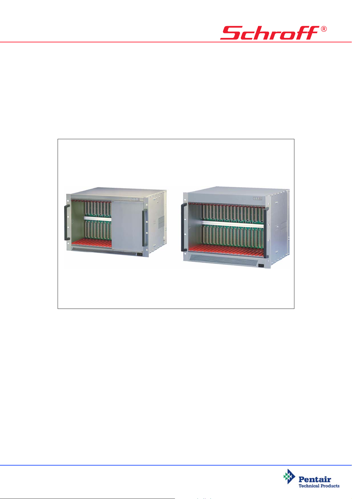
The Schroff VME subrack system consists of:
• A shielded 19“ subrack with front assembly area for
6 U front boards according to VME Standard (VITA 1-1994)
• A VME (VITA 1-1994) Backplane
• An open frame power supply with wide range input
• Speed controlled fans for cooling the boards
• Fan Control Module (FCM) for fan monitoring/controlling
• Display module
• Mains/line switch
• Rear assembly area for three 6 U, 4 HP Rear Transition Modules
The fans and the power supply are assembled on the bottom-hinged rear panel.
System differences:
The subracks 20836-716/-719 are identical in their construction. The only
difference is the depth (355 mm/475 mm).
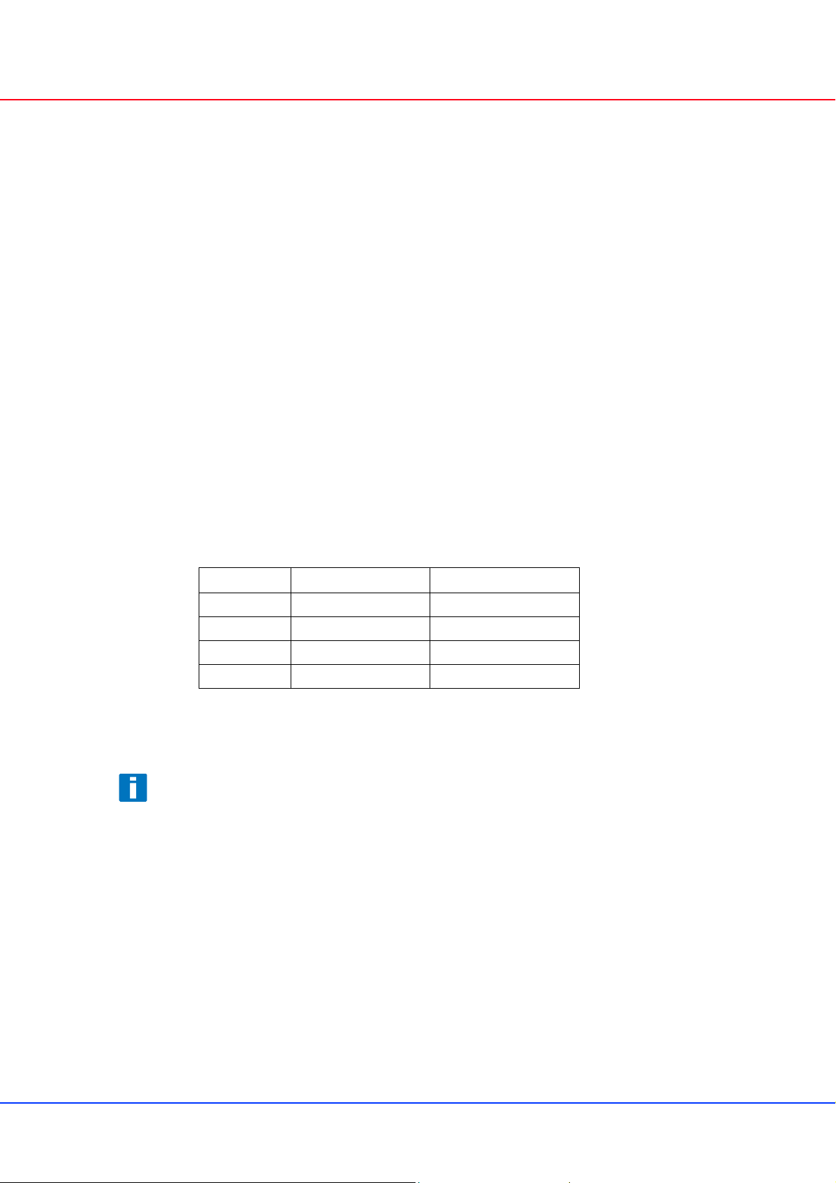
The subrack 20836-815 is identical to 20836-716 with the following exceptions:
20836-717 20836-815
Power supply 5 V / 60 A 5 V / 120 A
Fans 3 x 170 m³/h (100 cfm) 3 x 237 m³/h (140 cfm)
Backplane 12-Slot 21-Slot
Height 7 U 8 U
The 7 U system has a 0,5 U bottom plenum and a 0,5 U upper plenum. The 8 U
system has a 1 U bottom plenum and a 1 U upper plenum for more efficient
airflow and cooling.
Variations
The Schroff assembly service can customize your subrack system with:
• Different Backplane configurations
• Drive mounting cassettes
• Special power supplies
• A Chassis Monitoring Module (CMM)
More information in the catalogue or at www.schroff.biz
www.schroff.biz 4 R1.0, September 22, 2006
Artisan Technology Group - Quality Instrumentation ... Guaranteed | (888) 88-SOURCE | www.artisantg.com
 Loading...