


Pentair SB-SE-DOM-001B, SB-SE-TEC-001B, SB-CO-DIV-008B, SB-SE-BBX-001B, SB-SE-PER-001C Installation And User Manual
...
MAESTRO
SB-PF-ENS-002D
®
AUTOMATION
®
MAESTRO
CONTROL
28/04/2017 15:23:48
Water temp. :+29.0°C
pH:7.8 ORP:607mV
Cond:5264uS 3.28g/l
ESC
1 2 3 4 5
®
MAESTRO
PROBE UNIT
Water temperature
pH
ORP
VALID
Conductivity
pH
ORP
Conductivity
INSTALLATION AND USER GUIDE
IMPORTANT SAFETY INSTRUCTIONS,
READ AND FOLLOW ALL OF THE INSTRUCTIONS,
KEEP THESE INSTRUCTIONS
PENTAIR AQUATIC SYSTEMS SB-CU-IMP-052H (Rev. 03/2019)
EN
Pentair thanks you for your trust and for purchasing a MAESTRO®, a system for water analysis and its off-board display environment, with remote
monitoring of your pool via the MAESTRO application from Pentair available in the App store and Play store.
The MAESTRO® probe unit will make it possible for you to learn about the main parameters which regulate the life of your pool. The MAESTRO®
Control Center will automatically regulate your pool and permit you to control it remotely via the internet relay.
Please carefully read this user manual to fully benet from all of the functions of MAESTRO®. Store it carefully so that it can be consulted at any time.
Declaration of conformity
Directives – Harmonised standards
Pentair International Sarl - Avenue de Sévelin 18 - 1004 Lausanne - Switzerland
We declare, under our own responsibility, that the product meets the directives
SAFETY EN 62368-1:2014
EMC EN 61326-1: EN 301 489-3
EMF EN 62311
RADIO EN 300 220-2
MAESTRO (+ PARTS)
SB-PF-ENS-002D
PART NUMBERS:
SB-SE-PRO-001D SB-SE-TEC-001B SB-CO-DIV-008B
SB-SE-PER-001C SB-SE-BBX-001B SB-SE-DOM-001B
Other normative documents Authorised person for technical documentation
Pentair International S.a.r.l
Avenue de Sévelin 18
1004 Lausanne - Switzerland
Lausanne, 01/04/2019
Guillaume Goussé
European Vice President of Operations
Product specications: SB-PF-ENS-002D model
Operating temperature: 0° to 40° C Operating hygrometry: 40% at 75° C Power supply: 230 V ~, 50 Hz
Maximum operating altitude: 2,000 m Weight (excluding probes): 3.5 kg
Radio relay (external use): IP 65 Control Center + Probe Unit (internal use): IP 64
Internal display (internal use): IP 40 Internet relay (internal use): IP 20
Internet relay supply specications: 230 V/DC Jack 5.5/2.1 mm (external - negative): VEL05US060-EU-JA
Input: 100-240 V~50/60 Hz 0.18 A Output: 6.0 V 0.83 A max.
Waste treatment of electronic devices at the end of their service life:
The crossed-out bin placed on the main parts which make up the product indicates that it must not be disposed of together with the
household waste. It must be returned to an appropriate collection point for electronic device recycling (information available from the
local household waste collection service). This product contains potentially dangerous substances which may have adverse effects on
the environment and human health.
Customer Support: PISA, ITALY (8:30 A.M. to 4:30 P.M.) CET website: www.pentairpooleurope.com
- Warranty (excluding probes and consumables): 2 years
© 2019 Pentair International LLC, All rights reserved - The document is subject to change without notice
Trademarks and disclaimers: Maestro® and Pentair® are trademarks and/or registered trademarks of Pentair and/or its aliated companies.
Unless indicated otherwise, names and brands of others that may be used in this document are not used to indicate an aliation or endorsement
between the owners of these names and brands and Pentair. Those names and brands may be the trademarks or the registered trademarks of
these parties, or others.

Summary
PRESENTATION
> General operation
> Installation example
> Important safety instructions
> Functions
> Supplementary inlets/outlets
> Internet relay, installation and connection
> Internet relay - functioning and connection and account creation
> Probe unit, description
> Control Center, description
> Wall installation of MAESTRO housings
> Control Center, hygiene of electrical connections
> Control Center, settings basis
> General electrical/hydraulic installation
> Temperature probes
> Probe unit, electrical connections
> Control Center, ltration, connections and settings
> Control Center, disinfection, connections and settings
> Control Center, pH pump and lighting - connection and settings
> Control Center, lighting - connection and settings
> Control Center, heating pump - connections and settings, other alert messages
> Radio pairing
> Control Center, activity, internal menus
> Navigating the menus
> Radio relay - description
> Radio relay - installation
> Indoor display - Presentation
> Indoor display - Reading and intervention following a message
> Indoor display - pH reading
> Indoor display - Conductivity reading
> Indoor display - RedOx reading
> Indoor display - Reading and intervention following a message 2
> Indoor display - Radio mode
> Indoor display - Alarm mode
> Indoor display - Calib. mode, change of unit and voluntary correction of values
> Indoor display - Calibration of pH and RedOx probes
> Maintaining pH and RedOx probes and wintering
> Radio relays and indoor display and spare parts
> Updating of MAESTRO probe unit
> Technical characteristics and guarantee
> RedOx/pH/Free chlorine ratio
p 01
p 02
p 03
p 05
p 06
p 07
p 08
p 09
p 10
p 11
p 12
p 13
p 14
p 15
p 16
p 17
p 19
p 20
p 21
p 22
p 23
p 24
p 25
p 27
p 28
p 29
p 30
p 32
p 33
p 34
p 35
p 36
p 37
p 39
p 40
p 41
p 42
p 43
p 44
p 45
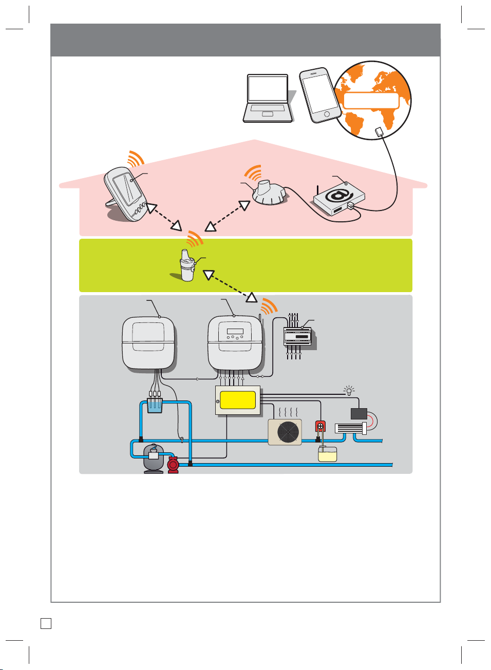
General operation
- Remote access to information and
and remote management of the pool:
Internal display
MAESTRO
Probe Unit
MAESTRO
Control Center
Internet relays
Radio relay
www.
automation
-piscine.eu
www.
automation
-piscine.eu
Internet box
4X Extension
6 inlet/4 outlet option
outlets
INTERNET
Electrical
cabinet
- Control of the equipment in the technical room:
MAESTRO supplies the dry contacts to which the classic equipment of the technical room is connected (ltration pump, disinfectant
[electrolyser, dosing pump], heat pump, lighting, AUX1).
Please do not use the individual automations of the equipment. MAESTRO will start/stop the devices.
- Receiving and processing information:
MAESTRO probe unit supplies the information required for regulating the MAESTRO Control Center; indeed, at the end of a dosing
(disinfection, addition of a pH regulator, heating pump, etc.), the device providing the information sends a value which makes it possible
for MAESTRO to rene its settings
01
pH
ORP
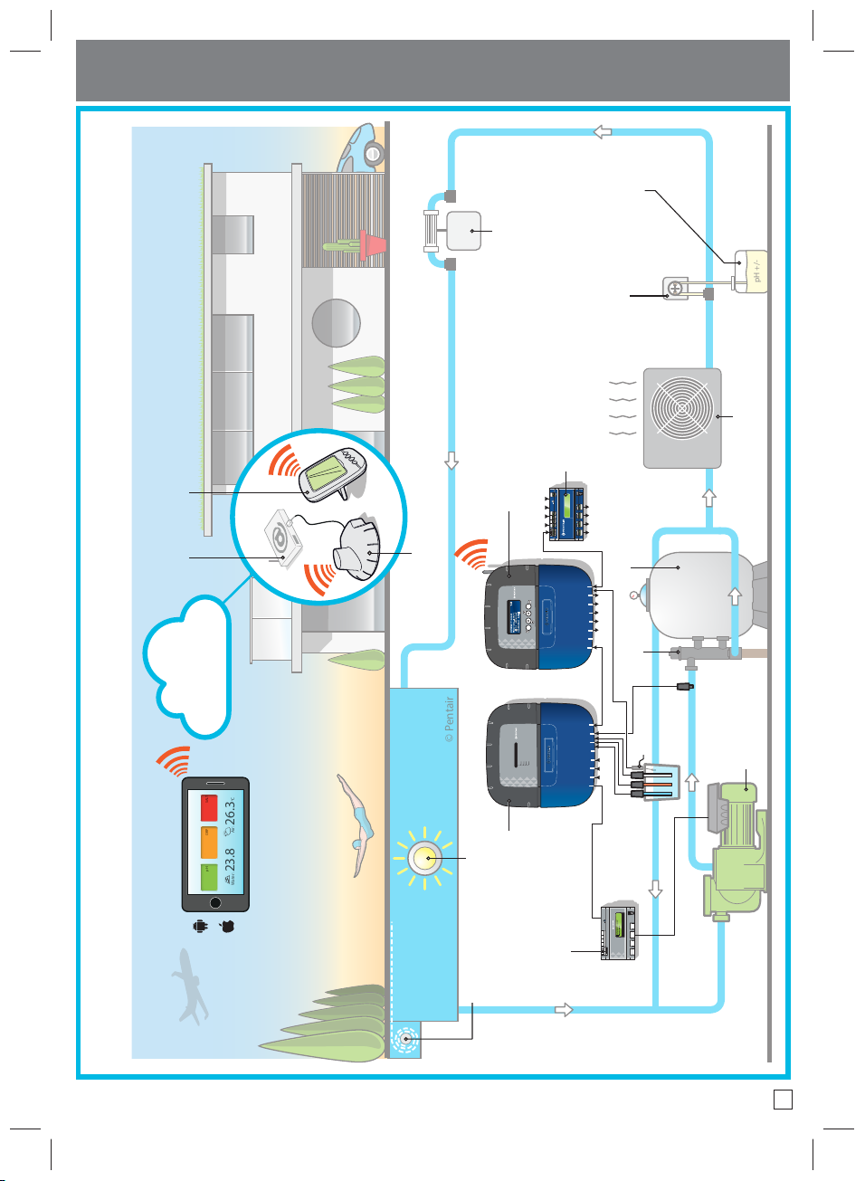
Installation example
Internal display
Internet box
*option
B Alarm
low level
3 Chlorinator
pH +/-
2 pH dosing pump
5 Heating
4X EXTENSION
6 inlets/4 outlets*
(4 outlets + 1 aux)
Control Center
Internet retransmitter
Filter
VALID
®
MAESTRO
ESC
28/04/2017 15:23:48
Water temp. :+29.0°C
Cond:5264uS 3.28g/l
pH:7.8 ORP:607mV
CONTROL
1 2 3 4 5A B C
backwash
cloud
Automatic
T°
domotique-piscine
®
Water temperaturepHORP
Conductivity
MAESTRO
PROBE UNIT
°C
Water: 23.8 Air: 26.3°C
7.2 614 mV 2.9 g/L
4 Lighting (ON/OFF + colour change)
Probe Unit
A pool which is fully automated and can be controlled remotely.
Manage your pool remotely
(4 speed #)
(4 probes and 3 inlets)
Flow switch
1 VS pump
pH+ORP+Cond.
USB
ON-OFF
BUS NOT
CONNECTED
Frost protection speed
4-speed mode
VS PUMP
SPEED-FC
MAESTRO EXTENSION
BUS
BUS IN
VS pump controller*
A Pool cover
position sensor
02

IMPORTANT SAFETY GUIDELINES, READ AND FOLLOW ALL OF THE INSTRUCTIONS, KEEP THESE INSTRUCTIONS
GENERAL POINTS
- DANGER - INSTALLERS, POOL SPECIALISTS AND OWNERS MUST CAREFULLY READ THESE WARNINGS AND ALL
INSTRUCTIONS BEFORE USING THIS PRODUCT.
- WARNING - Most countries regulate the construction, installation and operation of public swimming pools and spas, and the construction of
residential pools and spas. It is important to comply with these regulations, many of which directly regulate the installation and use of this product.
Consult your local building and health codes for more information.
- WARNING - This installation and user guide contains important information on the installation, operation and safety of this product. This guide
should be provided to the owner and/or user of this product.
INSTALLATION
- DANGER - RISK OF ELECTRIC SHOCK or electrocution
- BEFORE WORKING ON THIS DEVICE - Always cut the supply to the device at the circuit breaker before maintenance. Failure to do this may lead to
death or serious injury to service staff, pool users or others, due to an electric shock.
- DANGER - SERIOUS BODILY INJURY OR DEATH CAN RESULT IF THIS PRODUCT IS NOT INSTALLED AND USED CORRECTLY.
- WARNING - Before installing this product, read and follow the warnings and instructions of this guide. Failing to follow these warnings and
instructions may lead to serious injuries, death or material damage. Refer to www.pentairpooleurope.com for more information linked to this
product.
- WARNING - Connect the device to a differential interrupter. If this system is used to control the underwater lighting devices, a differential
interrupter must be installed upstream of these devices. Conductors downstream of the differential interrupter shall not be located in ducts,
junction boxes or enclosures containing other conductors, except if the conductors are also protected by a differential interrupter. Refer to valid
local codes for more details.
- WARNING - This product must be installed by an authorised or certied electrician or a qualied swimming pool professional. All of the applicable
installation codes and local regulations must also be respected. Poor installation will create an electrical hazard which could result in serious injury
or the death of pool users, installers or others due to electric shocks, and may also cause damage to property.
- DANGER - DISCONNECT THE POWER SUPPLY CONNECTIONS BEFORE WORKING ON THIS DEVICE; ELECTRICAL POWER MAY BE SUPPLIED TO THE RELAY
TERMINALS FROM OTHER SOURCES.
- WARNING – CHEMICAL BURN HAZARD: Make sure all pumps are switched off at the main circuit breakers at the domestic distribution board before
drilling into any pipes. Set rules for all handling related to electrical aspects, water and chemical products. Group the supply pumps and chemical
product tanks in a safe and secured area.
- WARNING - Do not use this product to control an automatic swimming pool cover. There is a risk that swimmers could become trapped under the
cover.
- WARNING – Devices which are not intended for use in single-family dwellings may require additional safety equipment to comply with local
regulations.
- WARNING – Except for remote controls, install components at a minimum of at least 1.5 m (5 feet) from the inside wall of the pool or spa.
- WARNING - This product is intended for use in swimming pool applications only.
- WARNING - A sucient equipotential earth connection (min. 4.5 mm2 recommended), in accordance with local regulations, is obligatory for all metal
components of the swimming pool, including the pool pump. This is necessary for the electrical safety as well as reduction of the corrosion risk.
03

USE
- DANGER - DO NOT LET CHILDREN OPERATE THIS EQUIPMENT.
- WARNING – Strictly respect the safety and handling procedures from the acid manufacturers, including protective measures for hands, body and
eyes during transfer and use of acid. Follow the prescribed safety precautions for handling muriatic acid intended for checking the water pH.
Muriatic acid may cause serious physical harm and may damage the swimming pool equipment. Extra care must be taken when installing,
maintaining and operating the acid pump feed systems. Acid is dangerous to handle and should be properly contained, transported, poured, stored
and dispensed.
- WARNING – Check the pH and sanitizer levels of the water before using the pool and make sure the ltration device is not obstructed.
- WARNING – Periodically use an independent pH and chlorine testing kit to ensure that the pH and chlorine is at a safe level. If the pH and Oxidation
Reduction Potential (ORP) or conductivity probes are broken, depleted or dirty with oils, lotions, or other contaminants, they can report inaccurate
results to the system causing incorrect water chemistry, which could harm people or equipment.
- WARNING – Consult the device display daily to ensure there are no alarm messages.
- DANGER – Water temperatures greater than 37.7° C (100° F) are a health hazard. Prolonged immersion in hot water may induce hyperthermia.
Hyperthermia occurs when the internal body temperature exceeds the normal temperature of 37° C (98.6 °F) by several degrees. Hyperthermia may
produce the following effects: (1) Unawareness of impending danger. (2) Failure to perceive heat. (3) Failure to recognise the need to leave the spa.
(4) Physical inability to leave the spa. (5) Harm to the foetus in pregnant women. (6) Unconsciousness leading to the risk of drowning. The use of
alcohol, drugs or medicine is a factor which increases the risk of hyperthermia in hot tubs and spas.
- WARNING - When mixing acid with water, ALWAYS ADD THE ACID TO THE WATER. Never add water to the acid. When adding a chemical product to
the swimming pool, carefully follow the manufacturer instructions.
- DANGER - DO NOT MIX SODIUM HYPOCHLORITE AND MURIATIC ACID.
- DANGER - Keep standard solutions away from children, ensure that the bottles are securely closed, store them in a dry and ventilated location and
do not let them freeze. The pH 4 calibration solution is acidic.
- DANGER - Batteries may contain dangerous substances. They should not be thrown into the bin, opened, thrown into re or recharged, as there is
a risk of explosion. Dispose of the batteries in accordance with the manufacturer instructions. There is a risk of explosion if the battery is replaced
by an incorrect type of battery. Handle a leaking battery with gloves. Remove the batteries if the device is not used for an extended period of time.
- DANGER - UV index information is supplied for information only and depends on the orientation and exposure of the radio relay.
For more information, we advise you to consult your dermatologist to inform you of the risks linked to your skin type.
04

Functions
Filtration control:
- By calculating the time according to the pool temperature (automatic mode).
- By programming a 24 hour cycle (makes it possible to benet from off hours).
- By integrating the frost protection function (activation of the ltration below 3°C)
- By giving priority to the heating, RedOx regulation, or pH (if the value of one of these references falls below
the set value, the ltration will start on the next hour, on the hour).
- Possibility to select the start time and end time of the ltration in automatic mode (to prevent noise at night).
- Possibility to increase or reduce the ltration time according to the use of the swimming pool (economical
mode = pool with a low number of visitors, turbo mode = pool with a high number of visitors).
- Possibility to change into “SHOCK” mode (forcing of the ltration and electrolyser for 24 hours) via the
supplied remote control or in the ltration menu.
- Automatic warning of the need to backwash the lter.
- Automatic detection of performance of lter backwash.
Lighting control:
- By programming on a 24h cycle.
Control of a salt chlorinator (or a dosing pump):
- By integrating the information supplied through the RedOx probe.
- Possibility to bring the electrolyser in hibernation at temperatures below 15°C, to prevent premature wear
of the electrodes.
Control of heating (heat pump, electric re-heater, heat exchanger, etc.):
- By incorporating information from the integrated temperature sensor.
Control of an AUX1 outlet:
- Possibility of controlling a pH dosing pump, or a cleaning robot, or a fountain, etc.
- By programming on a 24h cycle (excluding the pH pump).
MAESTRO also makes it possible to visualise, on its screen (in the technical room):
- Instant information from the pool (pH, RedOx, conductivity, water temperature, radio signal strength) as well
as from the previous 64 days.
- The daily functioning durations of ltration, of the electrolyser, of the heating and the AUX1 outlet as well as
those of the 64 previous days.
MAESTRO also provides information on the current status of the outlets (open/closed) and allows, via 4X
extension, various options to be added (peristaltic pump, sensors, inlet or outlet extension).
Therefore, in summer and winter, you no longer need to worry about your ltration and you limit the interventions
in the technical room to a bare minimum.
05
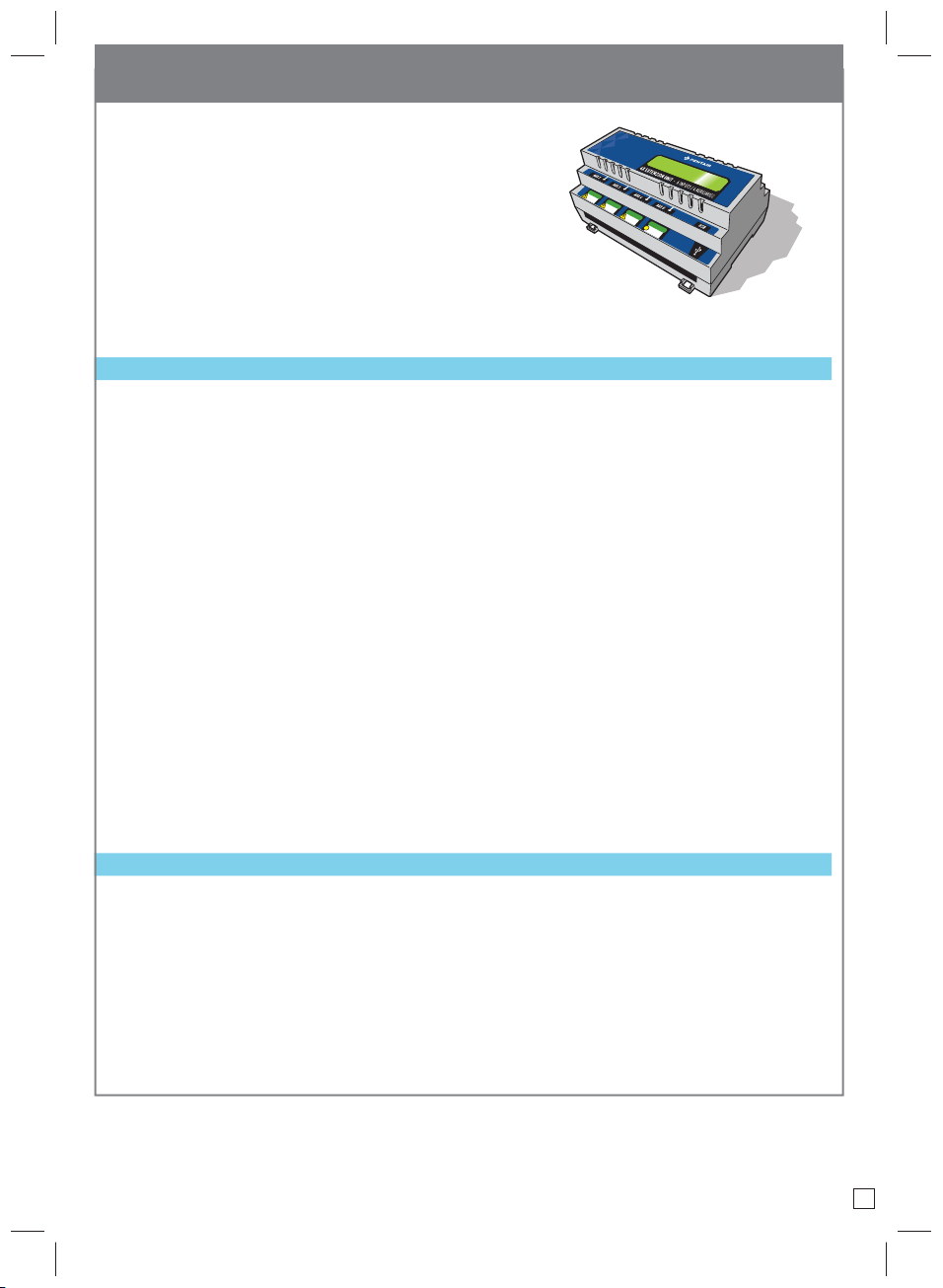
Supplementary inlets and outlets - (option with 4X Extension)
Requirement for additional connected equipment:
- If you need to connect more equipment, the 4X Extension unit
can be linked (ref SB-PF-INA-001A, available as an option).
24 V
Possible connections on the 4 In inlets:
- Disabled: Unused inlet, or makes it possible to disable an inlet which was previously used and to leave the
connection without any consequences.
- pH tank: Affects the relevant input to a dry contact (normally open, the contact closes when there is no more
product) at a low level in the pH tank. In case of low level, the indoor display shows a symbol of a fuel pump in
front of the numerical pH value, an identical indicator appears on the internet account summary and an
e-mail is sent following the pre-set alert settings.
- RedOx tank: Affects the relevant input to a dry contact (normally open, the contact closes when there is no
more product) at a low level in the disinfectant tank. In case of low level, the indoor display shows a symbol of
a fuel pump in front of the numerical RedOx value, an identical indicator appears on the internet account
summary and an e-mail is sent following the pre-set alert settings.
- Filtration stop: Any closure of a dry contact on the relevant input will result in the ltration immediately
stopping.
- Pool cover: Connecting a dry contact linked to closed sensor of a pool cover (the rolling shutter covers the
pool) automatically reduces daily duration production of a salt chlorinator.
- Not specied: Connecting a dry contact has no effect on the operation of the technical room but allows you
to view, on the history menu, the activation time of a piece of equipment that you want to monitor (relling, etc.)
as well as its real time status in the summary menu.
Possible connections to the 4 Aux outlets:
- Disabled: Unused outlet, or makes it possible to disable an outlet which was previously used and to leave the
connection without any consequences.
- pH: The relevant output closes a dry contact which makes it possible to control a pump which injects a pH
corrector. You must specify the type of pH- / pH + regulation in the relevant menu.
- If ltration is on: The relevant output closes a dry contact when the ltration starts (useful for UV lamps).
- Aux: The relevant output closes a dry contact
- Aux triggers ltration: The closure of this output automatically conditions the lter to start.
06
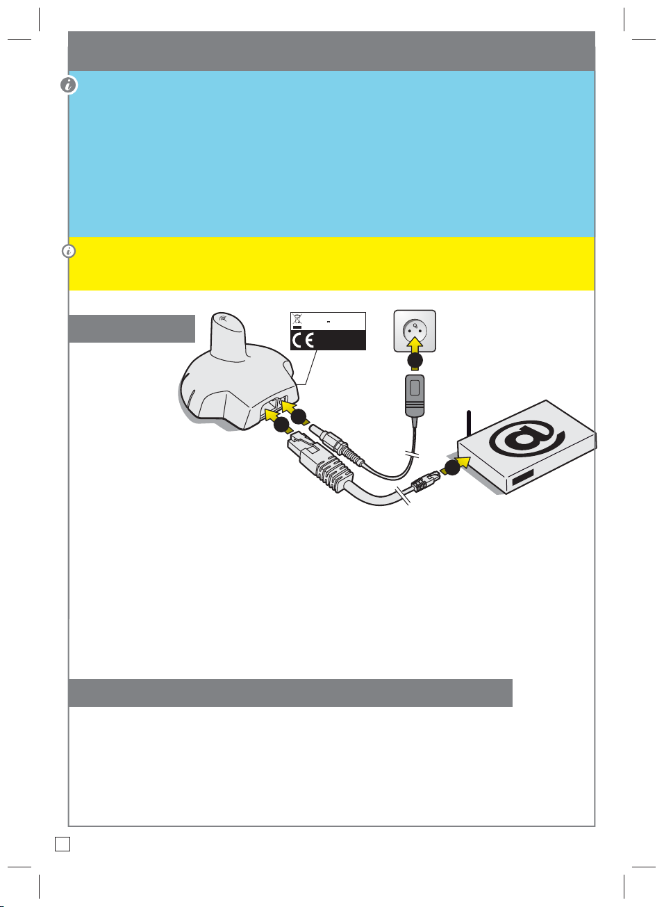
INTERNET RELAY - installation and connections
The INTERNET RELAY makes it possible to stay in contact with your installation. Thanks to the internet
relay, you have access to data in real time and can also work on the settings and orders from a computer or
smartphone connected to the internet.
Simply connect the internet relay to your internet box and connection to the www.domotique-piscine.eu
server is automatic.
By following the instructions, and after creating your free account at www.domotique-piscine.eu, you will be
able to connect to your installation in a few minutes. The controls imposed at MAESTRO via the internet are
effective in a few seconds.
Connecting the internet relay before the installation of MAESTRO to automate pairing of the devices is
preferable. However, if the internet relay was installed after MAESTRO, it can be paired via the radio menu,
see p 18.
SB-SE-BBX-001B
6V 0.8A / IP40
1
433.445 MHz / MADE IN ITALY
Pentair International LLC,
Ave. de Sevellin 18, CH-1004
LAUSANNE, Switzerland
2
2
1
Connection
1 - Connect one
end of the
supplied Ethernet
cable to the
Ethernet port of the internet
relay. Then connect the other end of the
Ethernet cable to a free Ethernet port of
your "box" or ADSL modem.
The supplied Ethernet cable can be replaced by an
equivalent cable with a maximum length of 100 m.
If you do not have a free Ethernet port on your "box" or ADSL modem, we advise you to obtain an Ethernet
switch to permanently connect your installation. Disconnect your Ethernet cables (except for the TV,
telephone) and connect your switch in their place. Then connect your internet relay and the previously
disconnected cable to the Ethernet switch. Then power your switch by connecting its power unit to the
mains supply.
2 - Connect the power cord and plug in the transformer unit. Only use the supplied power pack: 230 V/DC
Jack 5.5/2.1 mm ref. VEL05US060-EU-JA.
DHCP conguration (automatic IP address conguration)
The internet relay is automatically congured provided the DHCP server of your internet box is activated
(in
the vast majority of cases, the DHCP server is activated by default on installation of your internet box).
This function can be accessed via the management menu of your internet "box", refer to your internet
access supplier for more details.
The internet relay uses port 8001. Ensure that this port is open.
07
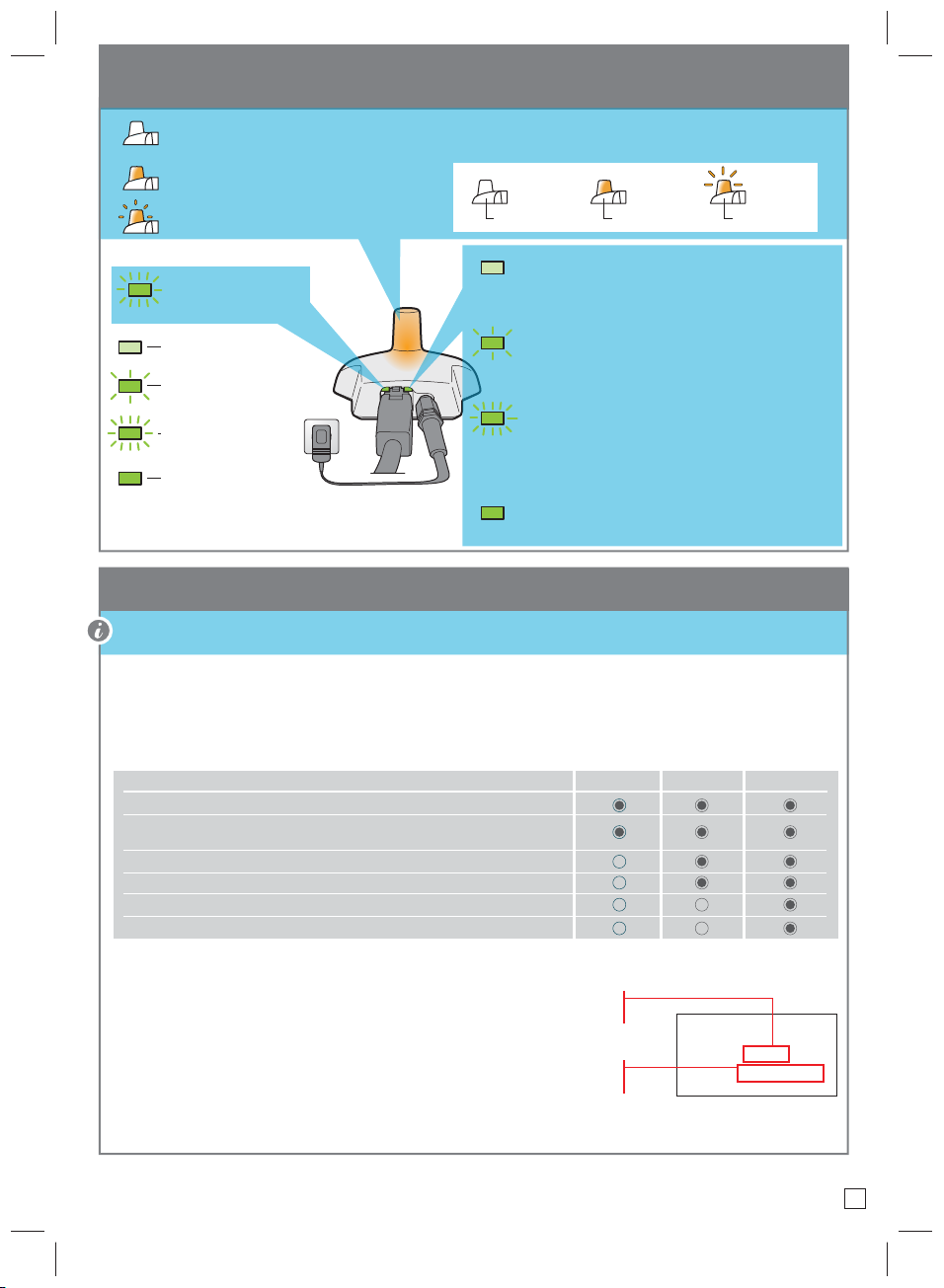
INTERNET RELAY - functioning
= not connected to the server
> Check the power supply, connection of the Ethernet cable and the internet connection.
Connected to the server
Data transfer in progress
Not lit Lit Flashing
Transmission of
> Check the connection of the 220-V supply.
data in progress
Initialisation fault or no supply
Not lit
Slow flashing
No network
> Check the connection of the Ethernet cable and
check the internet connection.
DHCP resolution in progress
Quick flashing
> Takes less than a second. If the flashing continues,
check the activation of the DHCP in the management
Lit
interface of your internet "box"
Network connection
> The internet relay is connected to the network.
Creation of a free account at www.domotique-piscine.eu
To monitor a pool for free on the internet, an account must be created in advance.
> Connect to www.domotique-piscine.eu
> Click My account
> Click Create an account
> Complete the fields of the PERSONAL INFORMATION window
- Account type: A poolbuilder account is reserved for professionals.
Choice of account
Reading of information: (pH, RedOx, Temp, etc.)
Comfort command: heating pump, lighting and if a 4x extension is connected, only the “Aux” outlets
are accessible
Setting the schedules: ltration, pH or RedOx priorities, etc.
Fixing the set point values: pH, water temperature
Assigning set point parameters: Injection time, pump volume, etc.
Setting installation parameters: type of disinfectant, pH+ or pH-, etc.
BASIC OWNER POOLBUILDER
> Complete the elds of the INSTALLATION INFORMATION window:
- Pool ID: The Pool ID number is on the side of the probe unit and the control center. It is a
ve-digit number. Do not use the serial number of the internet relay or the indoor display.
- ID Key: This is a unique security code which certies the device. It is on the same label.
> Click Create account
The account has been created.
MAESTRO
Pool ID: 12 345
ID Key: 1A:2B:33:99
08
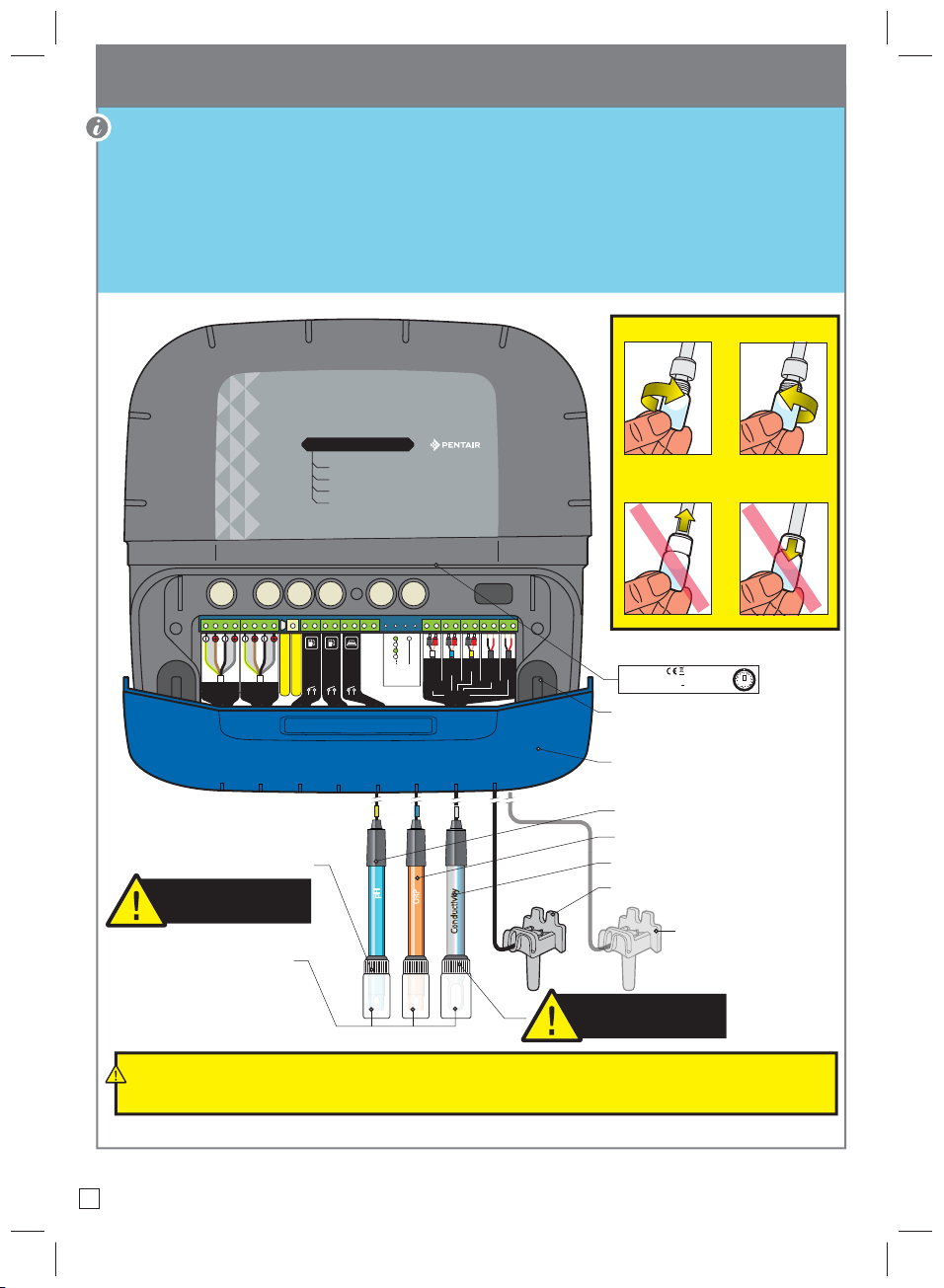
Probe Unit (P.U.), description
The multi-sensor measurement makes it possible to nd the water values. The length of the cables for the
pH and RedOx probes is voluntarily limited to 50 cm to ensure good probe reading precision.
The service life of the probes (according to the conditions of use) is around 18 years for the pH probe, 5 years
for the RedOx probe and a lifetime for the conductivity and temperature probes.
Only Pentair probes are compatible and guarantee proper functioning of the MAESTRO probe unit (see p40).
Tighten/loosen the probe bottles.
Data
Data
Power
Power
BUS
BUS
pH/ORP probe canister
The probe canisters must be filled
with potassium chloride or, failing
this, running water
with (with screw above) = probe out of the water
Probe canister
without = probe in the water
MAESTRO
PROBE UNIT
Water temperature
pH
ORP
Conductivity
Pool
Tank
empty
Radio learning
Firmware update via USB
covered
ORP tank
pH empty
®
Never push or pull on the fitted probe bottles
of the end plug.
Manufacturer tag
OFF
CONDUCT
PROBES
AIR T°
WATER T°
pH
ORP
ON
Serial number
SB-PF-ENS-002D SB-SE-PRO-001D
QC Passed
Pentair International Sarl
Avenue de Sévelin 18
CH-1004 Lausanne, Switzerland
Screw cover
(Isolating acid vapours and the circulating humidity)
via the screw hole)
Elastomer cover
(Insulator of acidic vapours
and humidity)
S/N 1234ABCD1234ABCD1234ABCD01
24 V / IP64 / 2.4 W
MADE IN ITALY
Mfg Year
Apr-2019
SCAN
ME
pH probe
RedOx probe
Conductivity probe
pH
ORP
Conductivity
Water temperature probe
Air temperature sensor
(option see p38)
The cap of the conductivity probe
may not be used for other probes.
The bypass must be isolated by closing the two valves before changing a probe which is at risk
of flooding.
09
pH
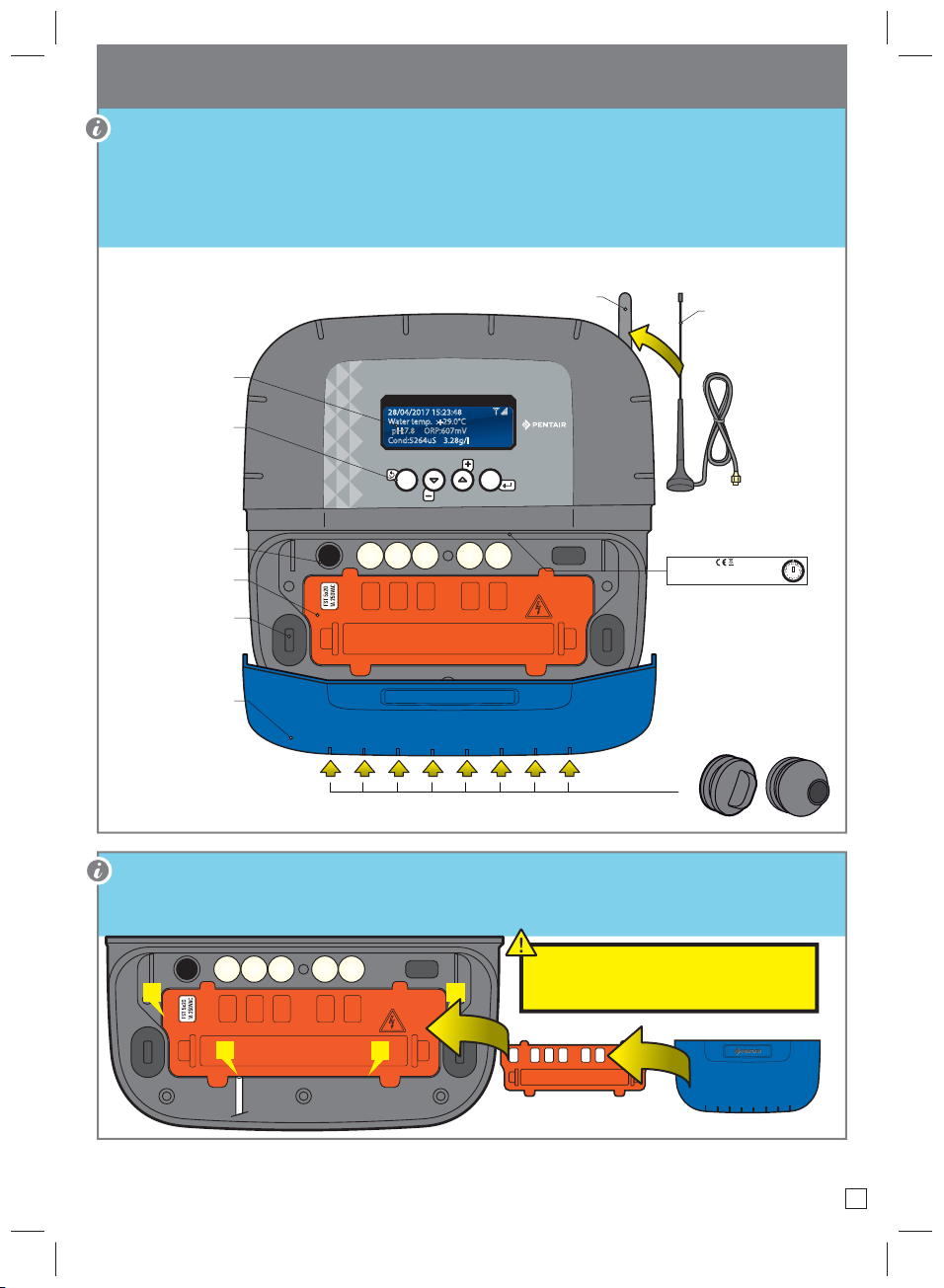
Control Center (C.C.), description
It is the brain of the system. SOLEO calculates automatically and controls the operating time of each piece
of the equipment.
It receives the orders via remote control (depending on the model) or via internet and launches the lighting
of the device involved.
The activity is stored in internal memory for 64 days (can be consulted by the user).
Screen
(4 x 20 characters)
(navigation in the menus)
(Insulator of acidic vapours
and humidity circulating
(Insulator of acidic vapours
Buttons
Fuse holder
(1A)
Connector cover
(Removable with a
flat screwdriver)
Screw cover
via the screw hole)
Elastomer cover
and humidity)
FRONT VIEW
MAESTRO
CONTROL
28/04/2017 15:23:48
Water temp. :+29.0°C
pH:7.8 ORP:607mV
Cond:5264uS 3.28g/l
ESC
®
VALID
Radio antenna
Magnetic, off-board radio
antenna option
3m
Ref.: SB-OP-ANT-001A
Manufacturer tag
Serial number
SB-PF-ENS-002D SB-SE-TEC-001B
QC Passed
S/N 1234ABCD1234ABCD1234ABCD01
Pentair International Sarl
Avenue de Sévelin 18
230 V 50 Hz~ / IP64 / 16 W
CH-1004 Lausanne, Switzerland
433.445 MHz
MADE IN ITALY
Mfg Year
Apr-2019
SCAN
ME
A safety cover which cannot be unclipped without a tool is positioned above the connectors which provide
the voltage. > Place a at screwdriver on the at part of clips 2 and 3, while keeping pressure on to unclip it.
After each intervention, put the
1
2
3
4
orange safety cover then and the soft
blue cover back in place.
10
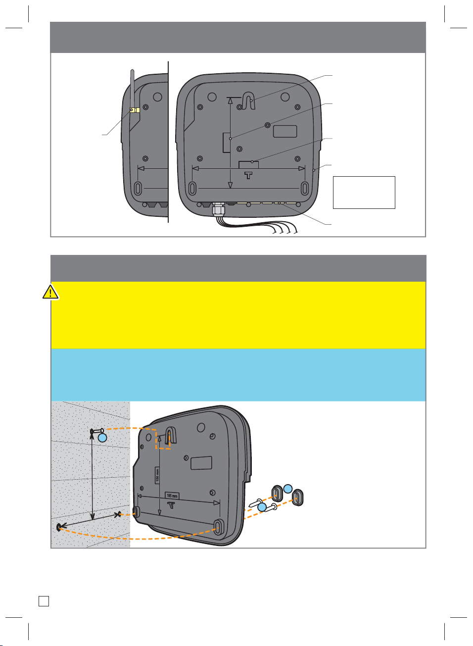
Back of devices
Probe UnitControl Center
Location of
fastening screw head
Centre axis between
both blocking screws
and fastening screw
Radio antenna
150 mm
185 mm
150 mm
185 mm
Centre axis of two
locking screws
Pool-ID label
Internet access codes
MAESTRO
Pool ID: 12 345
ID Key: 1A:2B:33:99
Caps
(Do not remove)
Wall mounting of the Probe Unit and Control Center
- This device is intended to be used inside, installed in a technical room which cannot be accessed by
children.
- Set the device at a height lower than 2 m using three screws (4 to 5 mm diameter) in appropriate plugs
for the type of support and x the device vertically on a clean support which is able to bear a minimum
vertical load of 5 kg.
Pierce three holes in accordance with the below dimensions then place 3 suitable plugs.
1 - Tighten the screw at the top, leaving 2 mm under the screw head, then hang the device on this.
2 - Place the 2 lower screws.
3 - Add the 2 lower screw covers to ensure a full seal.
1
m
m
0
5
1
m
m
5
8
1
11
3
2
185 mm
150 mm
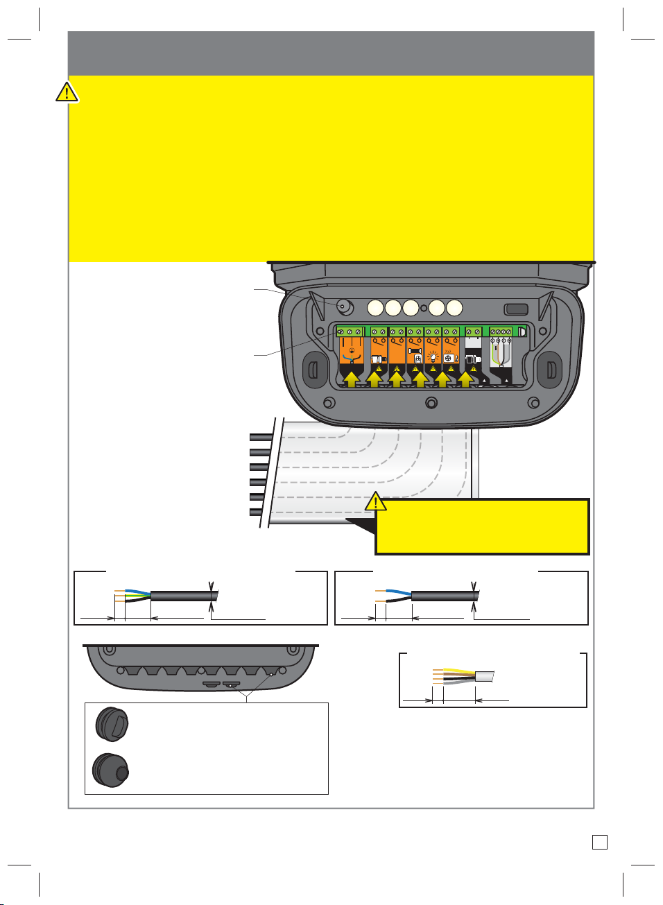
Hygiene of Control Center electrical connections
- The device must be installed by a qualied technician according to valid local regulation
- This device is permanently connected.
- The power supply to the device is cut by its interrupter, which must be close and must remain
accessible at all times.
- The device needs to be connected to the earth and its power supply needs to be protected by 16A 30
mA differential protection. This protection must be cut before any intervention on the device.
- Overvoltage category II (2,500 V peak) electrical device. If necessary, place overvoltage protection
equipment before the device.
- The device must be placed close to the electrical cabinet to aid connections (3 m max.).
Interchangeable fuse
FST 5x20 250 V AC 1 A fast
A1
Slotted screwdriver 2.5 mm/0.5-0.6 Nm
Screw terminals
POWER SUPPLY 230 V / 50 Hz +- 10%
FILTRATION PUMP - 230 V 10A max.
AUX 1 - 230 V 10 A max.
DISINFECTION - 230 V 10A max.
LIGHTING - 230 V 10 A max.
HEATING - 230 V 10 A max.
N L
230 V ~
AUX1 CL
The supply cable as well as the cables of the
dry power contacts must be placed in a plated
and closed channel under the device.
A2
ON?
24 V
RS-485
BUS
Compatible power supply cables 230 V
= RO2V (3 x 1.5 mm2 min.)
30 mm max. 5 mm
Caps
- must be installed if an outlet is not in use
(to stop any humidity or acidic vapour entering)
Cable ducts
- must be installed if an outlet is in use,
(to stop any humidity or acidic vapour entering)
Ø 8/8.8 mm
REAR VIEW
Compatible dry contact cables
= RO2V (2 x 1.5 mm2 min.)
30 mm max. 5 mm
Ø 8/8.8 mm
“BUS IN” (RS485) compatible cable
= VGV (4 x 0.75 mm2)
20 mm max. 5 mm
12
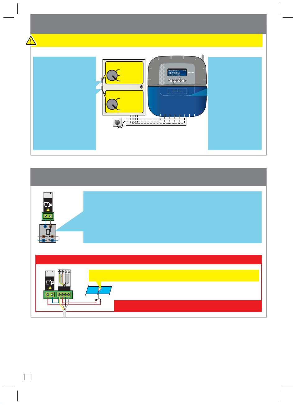
Control center, basis for settings in an existing installation
- RS-485 connections must remain within the building.
The 3-position interrupters
are kept.
The ltration interrupter
makes it possible to rinse
the lter using the FORCED
OPERATION/STOP positions.
If used with MAESTRO, use
position CLOCK.
The lighting interrupter
remains in STOP position.
FILTRATION
FORCED OPERATION
STOP
AUTO-CLOCK
LIGHTING
OPERATION
STOP
®
MAESTRO
CONTROL
28/04/2017 15:23:48
Water temp. :+29.0°C
pH:7.8 ORP:607mV
Cond:5264uS 3.28g/l
ESC
VALID
MAESTRO is connected
to a classic electrical
installation.
All of the outlets are
dry contacts which
are normally open
(NO) and can interrupt
up to 230 V-10 A
(above this, add a
contactor).
Basis for connections and settings in an existing installation
A1
ON?
A1 A2
A2
MAESTRO needs to obtain information on ltration; a parallel connection is
made on the ltration contactor coil at the A1 and A2 terminals. 230 V is
present when the ltration runs.
! If a variable speed pump is connected!
A1
ON?
A2
24 V
RS-485
BUS
Add a flow switch after the variable speed filtration pump.
Never 230 V on the ow switch!
13