

Pentair S060516G041, S060316G031, S060326G031, S060516G031, S060526G041 Instruction Manual
...
SPECTRACOOL™
Slim Fit Air ConditionerS
All modelS
INSTRUCTION MANUAL
Rev. I
© 2015 Pentair Equipment Protection 89116616
P/N 89116616

TABLE OF CONTENTS
Pentair Cooling Sales and Service Contacts ....................................................................................................4
Warranty and Return Policy ............................................................................................................................. 4
General Information ......................................................................................................................................... 5
Standards, CE, Declaration of Conformity ...........................................................................................................................5
Receiving The Air Conditioner .......................................................................................................................... 6
Handling and Testing The Air Conditioner ....................................................................................................... 6
PHASE MONITOR (460v Only) .....................................................................................................................................6
How to Read Model Numbers ........................................................................................................................... 6
General Safety Information .............................................................................................................................. 7
General Technical Information ......................................................................................................................... 7
Sequence of Operation .........................................................................................................................................................7
Cooling ............................................................................................................................................................................7
Component Operation ...........................................................................................................................................................7
Smart Controller (General Alarms)...............................................................................................................................7
Remote Access Control (Optional) ................................................................................................................................7
Door Switch ....................................................................................................................................................................7
Active Condensate Management ...................................................................................................................................7
Mounting .......................................................................................................................................................... 8
Tools Required For Installation: ...........................................................................................................................................8
External Mounting ................................................................................................................................................................8
Partial Recessed Mounting (Not Applicable to 300W Unit) .................................................................................................8
Full Recessed Mounting .....................................................................................................................................................10
Electrical Installation ..................................................................................................................................... 11
Principles of Operation .................................................................................................................................. 11
Smart Controller ............................................................................................................................................ 12
Introduction .........................................................................................................................................................................12
Energizing The Controller ..................................................................................................................................................12
Control Status Indication ....................................................................................................................................................12
Displaying and Changing Program Variables ....................................................................................................................13
Models with °C Controller ........................................................................................................................................13
Operating Parameters .................................................................................................................................................13
Alarm Parameters .......................................................................................................................................................13
Models with °F Controller ........................................................................................................................................13
Operating Parameters .................................................................................................................................................13
Alarm Parameters .......................................................................................................................................................13
Displaying Temperature Sensor #2 ...................................................................................................................................14
Compressor Restart Time Delay ........................................................................................................................................14
Alarm Output Contact .........................................................................................................................................................14
Alarm Input Connection ......................................................................................................................................................14
Alarm Condition Display .....................................................................................................................................................14
Remote Access Control .................................................................................................................................. 15
Air Conditioner Unit Communication Features (Optional) ................................................................................................15
USB Communication ....................................................................................................................................................15
Ethernet Communication ............................................................................................................................................15
SOFTWARE AND CONFIGURATION FILE DOWNLOADS .........................................................................................15
Remote Access Control Pin-out ..................................................................................................................................15
Technical Information .................................................................................................................................... 16
S06 Models 300/500W .........................................................................................................................................................16
S06 Schematic 300/500W ............................................................................................................................................16
S06 Wire Diagram 300/500W .......................................................................................................................................17
S06 Dimensional Drawings .........................................................................................................................................18
300W ..........................................................................................................................................................................18
500W ..........................................................................................................................................................................18
S06 Installation Instruction .........................................................................................................................................19
S06 300W Cutout Drawing ...........................................................................................................................................19
Surface Mount ..............................................................................................................................................................19
Full Recess Mount ........................................................................................................................................................19
S06 500W Cutout Drawing ...........................................................................................................................................20
Surface Mount ..............................................................................................................................................................20
Partial and Full Recess Mount ....................................................................................................................................20
S06 Unit Characteristics ..............................................................................................................................................21
S06 Components ..........................................................................................................................................................22
S10 Models 1000/1500W .....................................................................................................................................................23
- 2 -
© 2015 Pentair Equipment Protection
89116616

S10 Schematics ............................................................................................................................................................23
1000W 115V, 230V .....................................................................................................................................................23
1000W 460V ...............................................................................................................................................................23
1500W 115V ..................................................................................................................................................................24
1500W 230V ..................................................................................................................................................................24
1500W 460V ..................................................................................................................................................................25
S10 Wire Diagrams ......................................................................................................................................................26
1000W 115V, 230V .....................................................................................................................................................26
1000W 460V ...............................................................................................................................................................27
1500W 115V ...............................................................................................................................................................28
1500W 230V ...............................................................................................................................................................29
1500W 460V ...............................................................................................................................................................30
S10 Dimensional Drawing ...........................................................................................................................................31
1000/1500W ..............................................................................................................................................................31
S10 Installation Instruction .........................................................................................................................................32
S10 1000/1500W Cutout Drawing ................................................................................................................................32
Surface Mount ..............................................................................................................................................................32
Partial and Full Recess Mount ....................................................................................................................................32
S10 Unit Characteristics (115V, 230V) .........................................................................................................................33
S10 Unit Characteristics (460V) ...................................................................................................................................34
S10 Components (1 Phase) ..........................................................................................................................................35
S10 Components (3 pHASE) ........................................................................................................................................36
S16 Models 2000/2500W .....................................................................................................................................................37
S16 Schematics ............................................................................................................................................................37
2000W 115V ...............................................................................................................................................................37
2000W 230V ...............................................................................................................................................................37
2000W 460V ...............................................................................................................................................................38
2500W 115V ...............................................................................................................................................................38
2500W 230V ...............................................................................................................................................................39
2500W 460V ...............................................................................................................................................................39
4000W 460V ...............................................................................................................................................................40
S16 Wire Diagrams .....................................................................................................................................................41
2000W 115V ...............................................................................................................................................................41
2000W 230V ...............................................................................................................................................................42
2000W 460V ...............................................................................................................................................................43
2500W 115V ...............................................................................................................................................................44
2500W 230V ...............................................................................................................................................................45
2500W 460V ...............................................................................................................................................................46
4000W 460V ...............................................................................................................................................................47
S16 Dimensional Drawing ...........................................................................................................................................48
2000/2500W ..............................................................................................................................................................48
4000W ........................................................................................................................................................................49
S16 Installation Instruction .........................................................................................................................................50
S16 2000/2500W Cutout Drawing ................................................................................................................................50
Surface Mount ..............................................................................................................................................................50
Partial and Full Recess Mount ....................................................................................................................................50
S16 4000W Cutout Drawing .........................................................................................................................................51
Surface Mount ..............................................................................................................................................................51
Partial Recess Mount ...................................................................................................................................................51
S16 Unit Characteristics (115V, 230V) .........................................................................................................................52
S16 Unit Characteristics (460V) ...................................................................................................................................53
S16 Components )115V, 230V) .....................................................................................................................................54
S16 Components (460V) ...............................................................................................................................................55
Maintenance ................................................................................................................................................... 56
Compressor .........................................................................................................................................................................56
Inlet Air Filter (Field Installed Option) ................................................................................................................................56
How To Remove, Clean or Install an optional Inlet Air Filter ............................................................................................56
Condenser and Evaporator Air Movers ..............................................................................................................................56
Maintenance / Inspection Recommendations ............................................................................................................57
Basic Air Conditioning Trouble Shooting Check List - Remote Access Control Version ................................. 59
Basic Air Conditioning Trouble Shooting Checklist ...........................................................................................................60
3-Phase Basic Air Conditioning Trouble Shooting Check List - Remote Access Control Version ...................................61
3-Phase Symptoms and Possible Causes - Remote Access Control Version ..................................................................62
89116616
© 2015 Pentair Equipment Protection
- 3 -

PENTAIR COOLING SALES AND SERVICE CONTACTS
EUROPE:
Deutschland (Germany) +49 (0) 7082 794 0
France +33 (0) 3 88 90 64 90
Italia (Italy) +39 02 932 714-1
Polska (Poland) +48 22 209 98 37
Россия (Russia) +7 495 926 18 85
Sverige (Sweden) +46 (0) 8 683 6100
United Kingdom +44 (0) 1442 240 471
MIDDLE EAST:
UAE +971 4 378 1700
NORTH AMERICA:
México +52 555 280 1449
US & Canada +1 763 421 2240
SOUTH AMERICA:
Brasil (Brazil) +55 15 3363 9100
ASIA/SOUTH PACIFIC:
中国 (China) +86 400 820 1133
India +91 80 2845 4640
日本 (Japan) +81 (0) 45 476 02 81
Singapore +65 6768 5800
Or visit PentairProtect.com
WARRANTY AND RETURN POLICY
Visit www.pentairprotect.com/en/na/warranty for product warranty and return policy.
- 4 -
© 2015 Pentair Equipment Protection
89116616

GENERAL INFORMATION
STANDARDS, CE, DECLARATION OF CONFORMITY
PENTAIRTECHNICALSOLUTIONS
Minneapolis,MN55303‐1745,USA
2100HoffmanWay
+1.763.421.2240main
DeclarationofConformity
Issued by Manufacturer
Pentair Technical Products China dba Hoffman
declare at our sole responsibility, that these devices are designed and constructed according to the fundamental safety and health
requirements of the relevant EC directives.
Equipment Description: S0603X6GXXX, S0605X6GXXX, S1010X6GXXX, S1015X6GXXX, S1620X6GXXX,
S1625X6GXXX, S1640X6GXXX
Product Name: “ SpectraCool SLIM Fit” Control Cabinet Air-Conditioner
First Year of CE Marking: 2014
Ingress Protection: IP 34 – Ambient Side, IP 54 Enclosure Side
Applicable Directives: Directive /95/EC Low Voltage Directive
Laws for electrical equipment within certain voltage limits
Directive /108/EC EMC Directive relating to
Electromagnetic compatibility
Directive /65/EU on the restriction of the use of certain hazardous substances in
electrical and electronic equipment
Applicable Standards:
EN 378-1 and -2 Refrigerating systems and heat pumps-safety and environmental
requirements
EN 12100-1 and -2 Safety of machinery, equipment and facilities
EN ISO 13857 Safety of machinery-safety distances to prevent hazard zones being
reached by upper and lower limbs
EN 60335-1 and -2-40 Appliances-Safety, Particular requirements for electrical heat
pumps, air-conditioners and dehumidifiers
DIN EN 14511-2 (4) Air conditioner, Test conditions
DIN EN 14511-3 (4) Air Conditioner, Test methods
DIN EN 14511-4 (4.2, 4.5, 4.6) Air Conditioner, operating requirements
DIN 3168-4.5 Coolers for distribution boxes, concepts testing, marking
EN 61000-6-2 Electromagnetic compatibility (EMC)- Part 6-2: Generic standards -
Immunity for industrial environments
EN 61000-6-3 Electromagnetic compatibility (EMC)- Part 6-3: Generic standards –
Emission standard for residential, commercial, and light industrial environments
EN 60529, IEC 60529 Degrees of protection provided by enclosures (IP code)
EN 50581: Technical documentation for the assessment of electrical and electronic
products with respect to the restriction of hazardous substances
DIN 45635 Measurement of noise emitted by machines, airborne noise emission
For official DoC, go to http://www.pentairprotect.com/en/na/Compliance
Air Port Industrial Zone
Shuangyuan Road South
Chengyang District
Qingdao,
Shandong 266108 China
Authorizedby:
Manager,Lab&Certifications
Subject to Change Without Notice DOC: 00001 -A
89116616
7/15/2014
Tom Hurney Date
© 2015 Pentair Equipment Protection
- 5 -
RECEIVING THE AIR CONDITIONER
Inspect the air conditioner. Check for concealed damage that may have occurred during shipment. Look for dents,
scratches, loose assemblies, evidence of oil, etc. Damage evident upon receipt should be noted on the freight bill.
Damage should be brought to the attention of the delivering carrier -- NOT to Pentair Equipment Protection -within 15 days of delivery. Save the carton and packing material and request an inspection. Then file a claim with
the delivering carrier.
Pentair Equipment Protection cannot accept responsibility for freight damages; however, we will assist you in any
way possible.
HANDLING AND TESTING THE AIR CONDITIONER
If the air conditioner has been in a horizontal position, be certain it is placed in an upright, vertical or mounting
position for a minimum of five (5) minutes before operating.
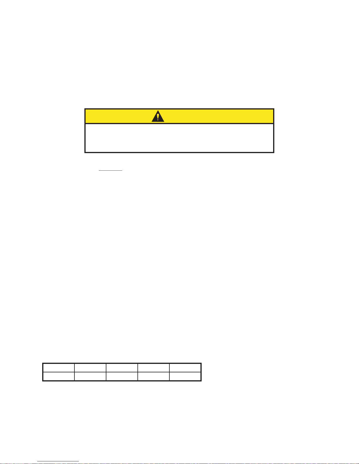
CAUTION
Do not attempt to operate the air conditioner while it is horizontal or
on its side, back or front. The refrigeration compressor is filled with
lubricating oil. This will cause permanent damage to the air conditioner
and also voids the warranty.
TEST FOR FUNCTIONALITY BEFORE MOUNTING THE AIR CONDITIONER TO THE ENCLOSURE.
Refer to the nameplate for proper electrical current requirements, and then wire the unit to a properly grounded
power supply using copper conductors only. Power supply wiring should be restrained after field installation to
ensure no contact with internal fan. Minimum circuit ampacity should be at least 125% of the amperage shown on
the unit nameplate. No other equipment should be connected to this circuit to prevent overloading.
Electrical circuit should be fused with slow blow or heating, air conditioning and refrigeration (HACR) rated circuit
breaker. Use a higher ampere rated circuit breaker or time-delay fuse that is closest to the nominal ampere
rating of the air conditioner, or sum of the individual component ampere ratings, to protect system electrical
circuits from short circuit or overload.
PHASE MONITOR (460V ONLY)
Note Location: Rear access panel, D-shaped sight port.
Reference S10 Dimensional Drawing on page 31; S16 Dimensional Drawing,
2000/2500W on page 48; S16 Dimensional Drawing, 4000W on page 49
This product is equipped with Phase/Voltage Protection. Please verify correct phasing and voltage before
operating. Note the fans may still operate if phasing is incorrect, but the compressor will not, so the unit
will not cool. Illuminated light on Phase Monitor indicates phase is correct.
If the light is not illuminated, disconnect power from the unit and swap any two power leads at the
terminal block. This should correct the phasing. The light should now illuminate when power is reapplied.
Immediately after applying power, the evaporator blower (enclosure air) should start running. Operate the air
conditioner with the compressor running for five (5) to ten (10) minutes. You will need to set the cooling controller
setpoint below the ambient temperature to operate the compressor.
Condenser air temperatures should be warmer than normal room temperatures within a few minutes after the
condenser impellers start.
See Sequence of Operation on page 7 for specifics on how the unit operates when powered up.
HOW TO READ MODEL NUMBERS
S10 15 2 6 G031
1 2 3 4 5
1. Identifies the type/family of air conditioner and the approximate height (i.e. S10 = Slim Fit family
about 1000mm high (10x100).
2. This is the air conditioner’s listed capacity in Watts at rated conditions. (i.e. 15=1500W (15x100) at
35/35 C)
3. 1 = 115 Volt, 2 = 230 Volt, 4 = 400/460 Volt.
4. 5 = 50 Hz only, 6 = 50/60 Hz or 60 Hz only.
5. Unique set of numbers for each air conditioner which identifies the accessories on a model.
- 6 -
© 2015 Pentair Equipment Protection
89116616

GENERAL SAFETY INFORMATION
Please observe the following general safety instructions when assembling and operating the unit:
• Assembly,installation and servicing may only be performed by properly trained specialists.
• When transporting the enclosure with the cooling unit externally mounted, always use an additional shipping brace
to support the cooling unit.
GENERAL TECHNICAL INFORMATION
The evaporator outlet sensor monitors the enclosure return air temperature to prevent ice buildup on the
evaporator coil. If the air temperature drops below -1°C, the compressor and condenser air mover(s) shut off.
They turn back on when the temperature rises above 15°C.
The compressor and the air movers are equipped with overload protection to guard against excess current and
temperatures.
SEQUENCE OF OPERATION
The air conditioner comes standard with smart controller. During cooling modes, the evaporator fan will be
running.
COOLING
When the enclosure temperature is above the cooling setpoint, power is applied to the compressor and
condenser air mover(s).
Operating the air conditioner below the minimum ambient temperature or above the maximum
ambient temperatures indicated on the nameplate voids all warranties. DO NOT adjust the setpoint to a
temperature lower than 20°C. Doing so can increase the likelihood of frost buildup on the evaporator coil.
The moisture that the sealed enclosure air can contain is limited. If moisture flows from the drain tube
continuously this can only mean that ambient air is entering the enclosure. Be aware that frequent
opening of the enclosure’s door admits humid air that the air conditioner must then dehumidify.
COMPONENT OPERATION
NOTE: Do not reduce the time delay setting on the controller to less than 120 seconds. This may
cause the compressor to cycle too rapidly, shortening the life of the compressor.
SMART CONTROLLER (GENERAL ALARMS)
See Smart Controller on page 12
REMOTE ACCESS CONTROL (OPTIONAL)
See Remote Access Control on page 15
DOOR SWITCH
Several door switches may be connected in series and operated on one cooling unit. The door switch
only supports a floating connection, no external voltages. Remove jumper from terminals 3 and 4 of the
connector and connect the door switch to the two terminals if a door switch is available.
NOTE: The alarm code “TP” will appear on the controller display if this jumper wire is removed
without the addition of a customer installed door switch.
ACTIVE CONDENSATE MANAGEMENT
At low temperatures and high humidity levels inside the enclosure, condensation may form on the
evaporator coil.
Slim Fit air conditioners continuously evaporate the water that may be in the drain pan due to
condensation from the evaporator coil into the external air stream. Excess condensate is routed
downwards out of the air conditioner via a barbed fitting at the bottom of the condenser side of the unit. A
10 mm (.40) inside diameter tube can be attached to the fitting and routed to a nearby drain.
89116616
© 2015 Pentair Equipment Protection
- 7 -
MOUNTING
TOOLS REQUIRED FOR INSTALLATION:
• #2 Phillips screwdriver
• 6.5 mm slotted screwdriver
• 13 mm wrench or socket
EXTERNAL MOUNTING
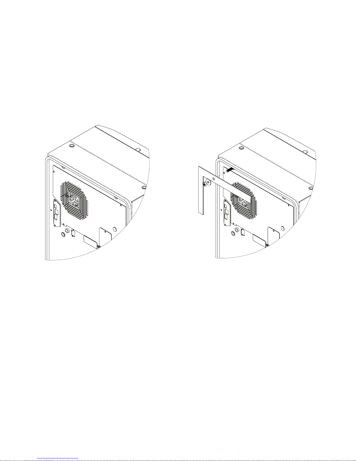
1. Using the mounting gasket kit provided with the unit, install gasket to the air conditioner, see Figure
1.
2. Screw the supplied grub screws into the blind nuts on the rear of the unit, see Figure 2.
3. Secure the unit to the enclosure using the supplied washers and nuts. Use caution to avoid damaging
the gasket while positioning the unit.
Figure 1 Figure 2
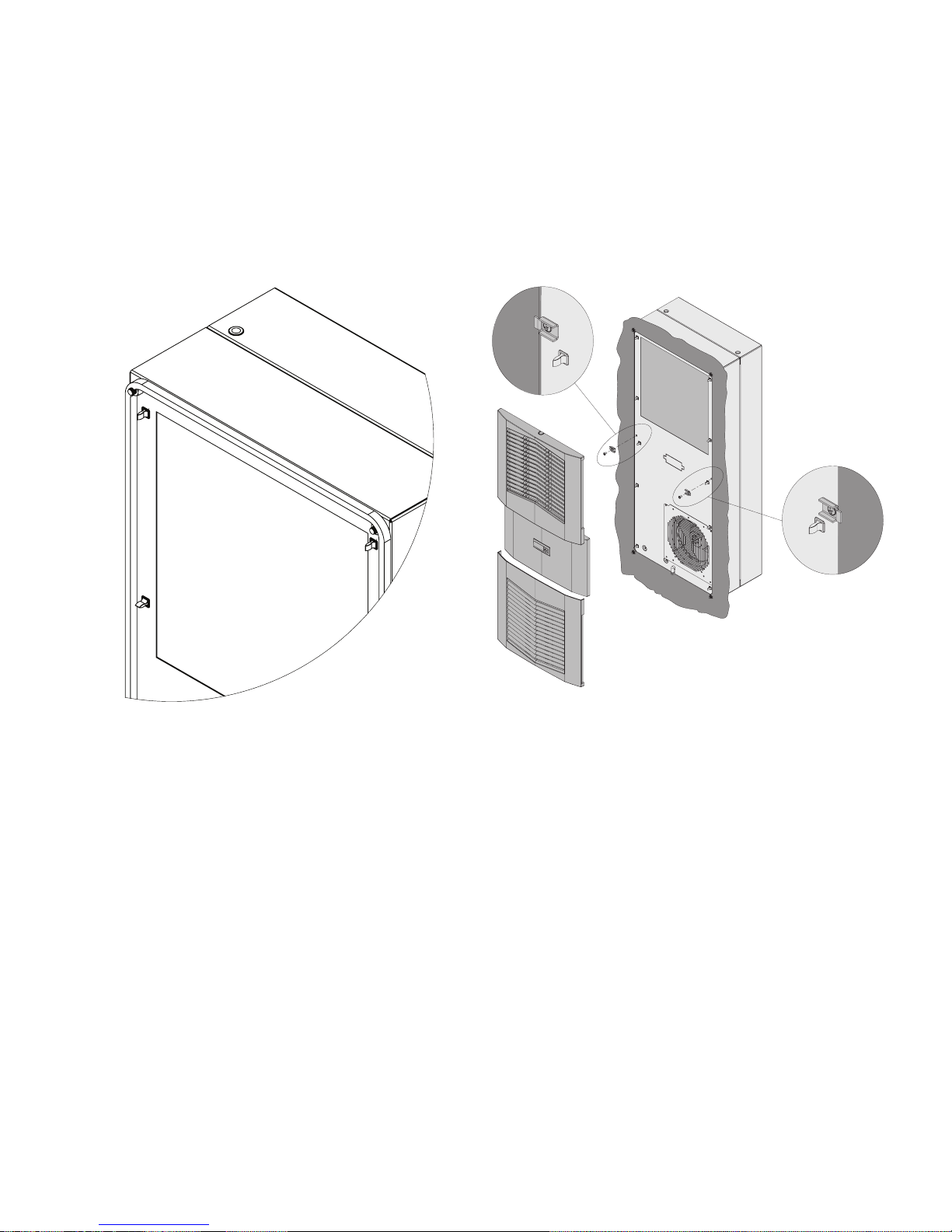
PARTIAL RECESSED MOUNTING (NOT APPLICABLE TO 300W UNIT)
1. Carefully remove the louvered grille, and where applicable, remove the center panel from the
enclosure by pulling forwards. See Figure 3 on page 9.
2. Carefully disconnect the connectors from the rear of the smart controller.
3. Remove the two front screws.
4. Remove the four nuts on the front panel and pull the panel assembly forward approximately 5 cm.
See Figure 4 on page 9.
5. Disconnect the fan electrical connection.
6. Remove the front panel.
7. Remove the four standoffs, leaving the grub screws in place.
8. Push the rear enclosure half into the mounting cutout and secure it with the four standoffs. See
Figure 5 on page 9.
9. Push the smart controller cables through the rectangular hole in the front panel.
10. Reconnect the fan electrical connector.
11. Mount the front panel using the nuts removed in step 4.
12. Install two front screws.
13. Carefully reconnect the smart controller connectors .
14. Push the louvered grille and, where applicable, the center panel, onto the front panel. See Figure 6
on page 9.
- 8 -
© 2015 Pentair Equipment Protection
89116616
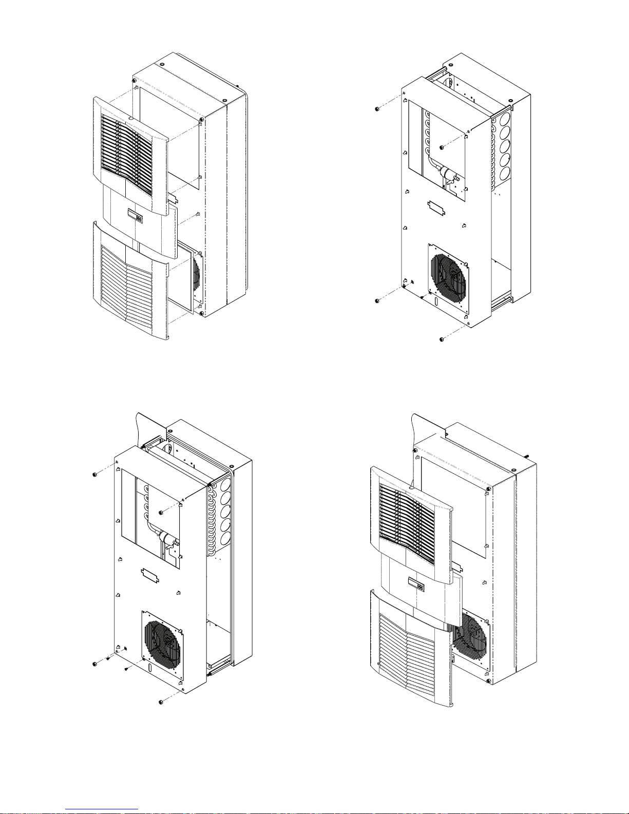
Figure 3
Figure 4
Figure 5 Figure 6
89116616
© 2015 Pentair Equipment Protection
- 9 -
FULL RECESSED MOUNTING
1. Carefully remove the louvered grille, and where applicable, remove the center panel from the
enclosure by pulling forwards.
2. Carefully disconnect the connectors from the rear of the smart controller.
3. Using the mounting gasket kit provided with the unit, install gasket to the air conditioner front panel.
See Figure 7.
4. Remove the four nuts on the front panel.
5. Push the unit into the mounting cutout and secure it using the nuts removed in step 4.
6. Carefully reconnect the smart controller.
7. Push the louvered grille and, where applicable, the center panel, onto the front panel. See Figure 8.
- 10 -
Figure 7
© 2015 Pentair Equipment Protection
Figure 8
89116616
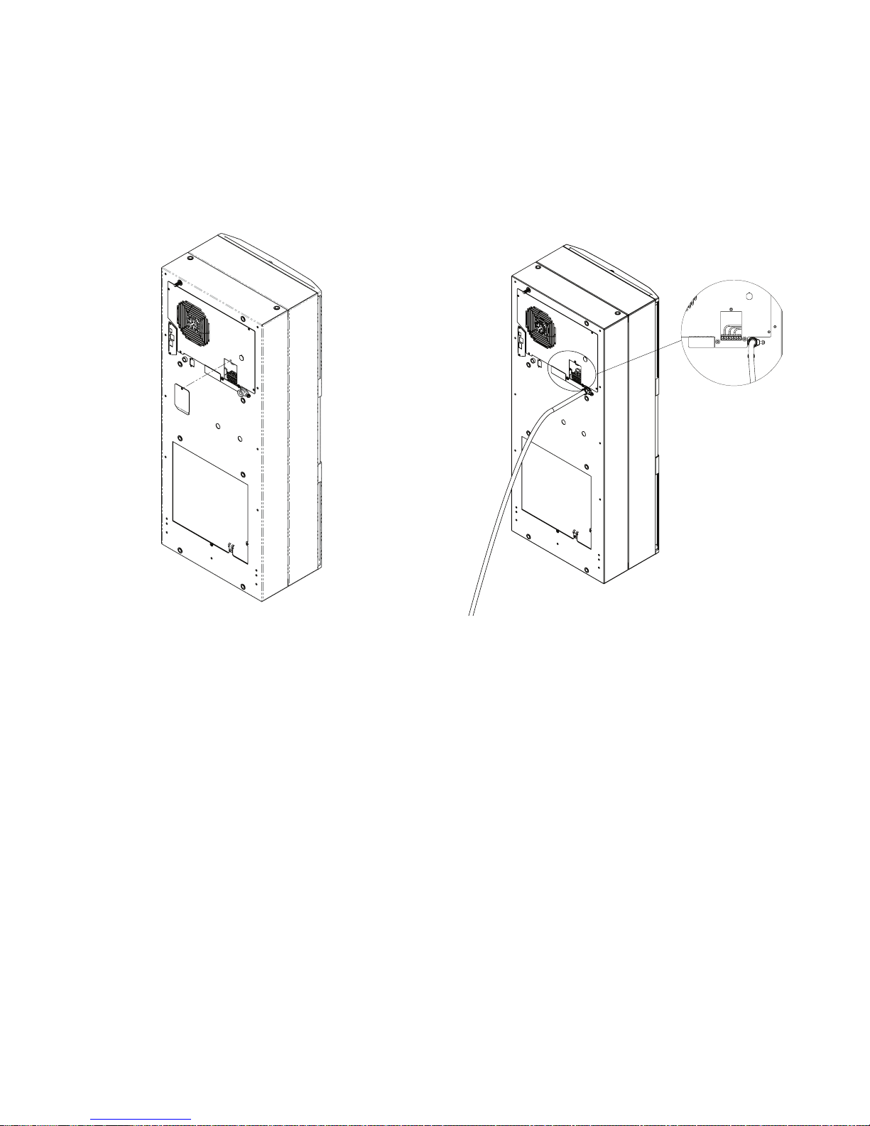
ELECTRICAL INSTALLATION
1. Loosen the screw on the evaporator access panel and remove the power access panel. See Figure 9.
2. Push the power supply wire through the strain relief.
3. Connect the wire to the terminal block per the label.
4. Reinstall the power access panel and screw.
5. Tighten the screw on the strain relief to secure the supply wire, see Figure 10.
NOTE: Use a higher ampere rated circuit breaker, or time-delay fuse, that is closest to the
nominal ampere rating of the air conditioner, or sum of the individual component ampere ratings,
to protect the system electrical circuits from short circuit or overload.
Figure 9
Figure 10
PRINCIPLES OF OPERATION
If electrical power to the air conditioner is interrupted and reapplied, the compressor may take up to five (5)
minutes to restart due to the high back pressure of the compressor.
NOTE: The controller includes a nominal time delay setting of 5 minutes. Do not decrease the
time delay setting to less than 2 minutes, as this may cause rapid cycling of the compressor,
which may reduce the life of the compressor.
89116616
© 2015 Pentair Equipment Protection
- 11 -
SMART CONTROLLER
INTRODUCTION
The smart controller is a parametric controller for the complete management of air conditioners. All settings are
pre-programmed at the factory. Cooling set-points, cooling differential and high/low temperature alarm setpoints can be adjusted by the user. Alarms are outputted through a relay contact.
NOTE: The polyester tape on the top side and the neoprene seal around the connectors
assure IP34 protection for the controller. Do not remove.
ENERGIZING THE CONTROLLER
The controller is wired and programmed at the factory to be energized when power is applied to the air
conditioner.
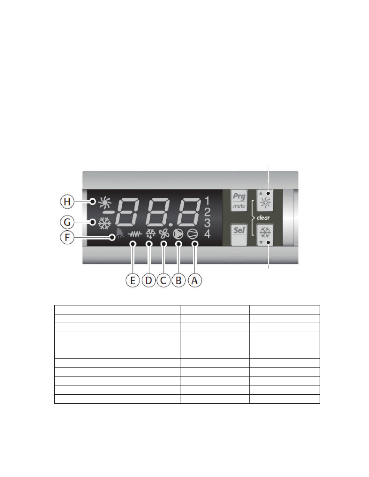
CONTROL STATUS INDICATION
The display has numerous symbols that indicate if the controller is heating, cooling, alarming, if the compressor
is enabled, and if the ambient fan is enabled. The 3 alpha-numeric characters further describe alarms and show
the cabinet temperature by default.
NOTE: The Slim Fit air conditioners do not come standard with a heating option.
Heating (sun)
Cooling
(snowake)
SYMBOL COLOR ICON ON ICON FLASHING
1 AMBER Compressor On Start-up Request
2,3,4 AMBER Not Used Not Used
A AMBER Compressor On Not Used
B AMBER Evaporator Fan On Not Used
C AMBER Not Used Not Used
D AMBER Not Used Not Used
E AMBER Not Used Not Used
F RED Alarm Active Not Used
G AMBER Controller Active Not Used
H AMBER Not Used Not Used
NOTE: On the smart controller, the display symbols for “H” and “E” are not suppose to
turn ON. If they do turn on, simply hold the “Heating” button for 5 seconds to disable
them. Then hold the “Cooling” button for 5 seconds until the snowflake symbol (“G”)
displays.
- 12 -
© 2015 Pentair Equipment Protection
89116616

DISPLAYING AND CHANGING PROGRAM VARIABLES
Access: To view and/or change parameters, press and hold the Prg and Sel buttons for greater than 5 seconds.
Press the up or down arrow buttons until 22 is displayed, then press Sel button. When S-P is displayed, press Sel.
Navigation: Press up or down arrows to display sub-menus then press Sel to select the desired sub-menu. In the
sub-menu, use up or down arrows to display parameters for viewing or changing and press Sel. Use Prg button to
back out of menu levels as desired.
Adjust: Use the up or down arrows to change the parameter value then push Sel to save that setting. If Sel is not
pressed, the change to the value will not be saved. Navigate to and change other parameters as desired. When
finished, push Prg to back out of the sub-menus to the main menu.
NOTE: The display will revert to normal temperature display mode if no buttons are pressed for
60 seconds.
MODELS WITH °C CONTROLLER
Cooling turns on at r01 (Setpoint), and off at r01 (Setpoint) - r02 (Differential).
For example, using default values from the table below, cooling will turn on at 35 °C (setpoint), and turn
off at 30 °C (setpoint – differential).
OPERATING PARAMETERS
Parameter Description Default Value Range
r01 Cooling set-point 35°C 20°C to 55°C
r02 Cooling differential 5°C -
ALARM PARAMETERS
Parameter Default Value Range Description
P16 55°C - High Temperature Alarm
P19 14°C - Low Temperature Alarm
MODELS WITH °F CONTROLLER
Cooling turns on at r01 (Setpoint) + r02 (Differential), and off at r01 (Setpoint).
For example, using default values from the table below, cooling will turn on at 87 °F (setpoint +
differential), and turn off at 80 °F (setpoint).
OPERATING PARAMETERS
Parameter Description Default Value Range
r01 Cooling set-point 80°F 72°F to 120°F
r02 Cooling differential 7°F -
ALARM PARAMETERS
Parameter Default Value Range Description
P16 125°F - High Temperature Alarm
P19 40°F - Low Temperature Alarm
89116616
© 2015 Pentair Equipment Protection
- 13 -

DISPLAYING TEMPERATURE SENSOR #2
Sensor number 2, the air outlet or evaporator coil sensor, can be viewed at any time by pressing the up or down
arrow button on the front panel of the controller display. The display will revert to displaying temperature sensor
number 1 (the evaporator air inlet temperature) after 60 seconds. Both sensors can also be read through the
Ethernet and USB connections with the optional communications board.
COMPRESSOR RESTART TIME DELAY
A factory set 5 minute (300 second) restart delay exists to reduce residual back pressure before allowing the
compressor to restart. The compressor will stay off for the entire restart duration after the compressor is
disabled. A flashing 1 on the controller display will indicate the unit is in a compressor restart delay while calling
for cooling. If the time delay is reduced to less than five (5) minutes, this may cause reduced compressor life.
ALARM OUTPUT CONTACT
The smart controller has a normally open dry contact alarm output with a resistive load rating of 250 VAC at 3
amps. A connector located on the enclosure side of the unit provides a 2 pin connection to this output marked
YEL/ALARM.
ALARM INPUT CONNECTION
The smart controller can accept a dry contact/switch input via the connector terminals marked WHT/DS1 and
WHT/DS2 located on the enclosure side of the unit. This input is associated with the controller display alarm
mnemonic TP (door open and/or smoke detected). To use this feature, remove the jumper wire connecting
terminals DS1 and DS2 and replace with customer supplied wires from the enclosure door switch to DS1 and DS2
terminals.
ALARM CONDITION DISPLAY
There are seven possible non-latching alarm conditions detectable by the controller and are indicated on the
controller display. All alarms can also be accessed through the Ethernet and USB connections with the optional
communications board.
Alarm Mnemonic Description Cause Result Alarm Relay
TP General Alarm
LA High Pressure Warning
E1
E2
Ht
Lt
A1 Frost Alarm
NOTE 1: Air inlet temperature sensor will default to air outlet temperature sensor. Cooling set point defaults to 10°C.
NOTE 2: Unit continues to operate without evaporator freeze protection.
NOTE 3: The MALF high pressure switch is optional.
Air Inlet Temperature
Sensor Alarm
Air Outlet Temperature
Sensor Alarm
High Temperature Alarm
Default = 55°C
Low Temperature Alarm
Default = 14°C
Door open and/or smoke
detected
MALF high pressure
switch opens (See Note 3
below)
Sensor Failure See Note 1 below Relay Contacts Close
Sensor Failure See Note 2 below Relay Contacts Close
Air inlet temperature
greater than 55°C
Air inlet temperature less
than 14°C
Air outlet temperature
less than or equal to
-1.0°C
Unit turns off for duration
of alarm
No effect on function N/A
No effect on function Relay Contacts Close
No effect on function Relay Contacts Close
Compressor and
Condenser fan off for
duration of alarm
Relay Contacts Close
Relay Contacts Close
- 14 -
© 2015 Pentair Equipment Protection
89116616

REMOTE ACCESS CONTROL
AIR CONDITIONER UNIT COMMUNICATION FEATURES (OPTIONAL)
An optional communication board offers capabilities that include SNMP, EtherNet/IP, Modbus TCP and Profinet
protocols through Ethernet and Modbus RTU protocol via USB. Pentair has a PC Interface Tool available for
download that can utilize either mode to communicate with the air conditioner unit.
USB COMMUNICATION
This communication mode allows direct connection of a PC to the air conditioner unit. The protocol
supported is Modbus RTU. Use the Pentair AC monitor to communicate with the air conditioner unit. A
MINI-b USB connection is included with this option.
ETHERNET COMMUNICATION
This communication mode allows remote connection to the air conditioner unit using SNMP, EtherNet/IP
and Modbus/TCP, and Profinet protocols. Customers using their own software can download a MIB file for
SNMP, EDS file or EtherNet_IP Object file for EtherNet/IP, Coil Register file for Modbus TCP and GSDML
file for Profinet.
Note: ACU has a default IP Address of 192.168.1.2
Both Ethernet and USB communication modes allow the ability to:
• Read ACU inlet and outlet air temperatures
• Read and change Cooling Set-point and Cooling Differential
• Read and change High and Low Temperature Alarm Settings
• Read and change Gateway IP Address, Device IP Address, Subnet Mask, Trap IP Address and SNMP Community
• Read and change Unit Identification
• Read and change the type of IP addressing (static or dynamic)
• Read current Alarm Status
• Read MAC address
SOFTWARE AND CONFIGURATION FILE DOWNLOADS
The Pentair AC monitor, MIB file, EDS file, EtherNet_IP Object file, Coil Register file and GSDML file for
Profinet can be downloaded from www.pentairprotect.com/en/na/Product-EnclosureCoolingHeating.
REMOTE ACCESS CONTROL PINOUT
U1 OUTPUTS
U2 INPUTS
U3 DATA
FUNCTION NAME PIN #
COOL No1 1
C1/2 2
C1/2 3
ALARM RELAY OUTPUT No5 12
C5 6
ENCLOSURE DOOR SWITCH ID1 8
MALFUNCTION NC SWITCH ID2 1
NA ID3 (na) 9
NA ID4 (na) 2
DIGITAL INPUT GROUND ID GND 3
T1, EVAP IN THERMISTOR B1 13
T2, EVAP OUT THERMISTOR B2 12
T1, T2 GND GND 6
NA B3 11
CONTROLLER POWER G 7
CONTROLLER POWER G0 14
POWER 1
GROUND 2
DIRECTION 3
DATA 4
89116616
© 2015 Pentair Equipment Protection
- 15 -
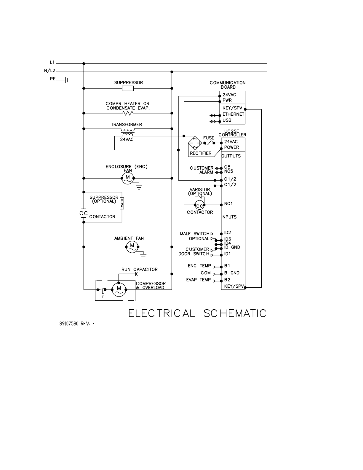
TECHNICAL INFORMATION
S06 MODELS 300/500W
S06 SCHEMATIC 300/500W
- 16 -
© 2015 Pentair Equipment Protection
89116616

S06 WIRE DIAGRAM 300/500W
89116616
© 2015 Pentair Equipment Protection
- 17 -
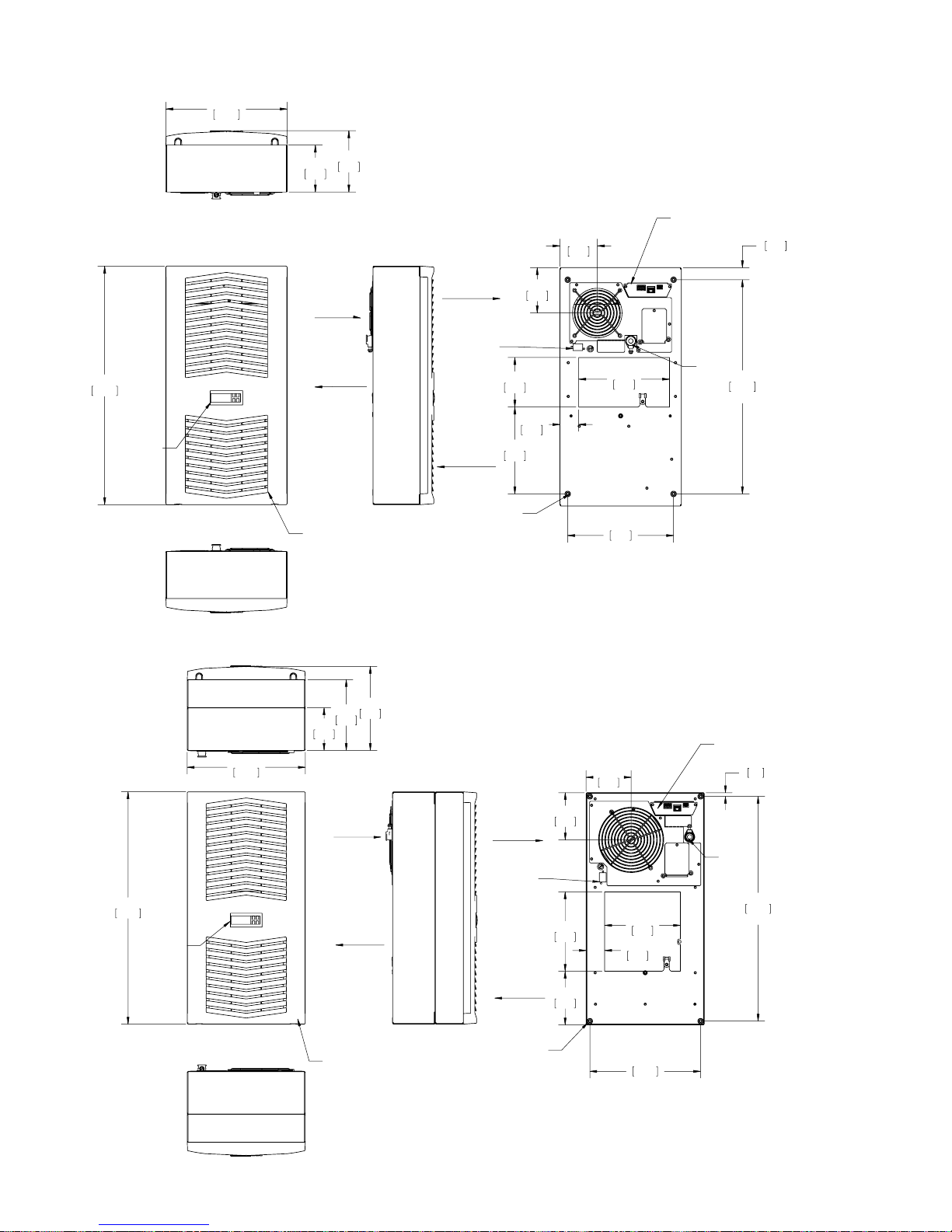
S06 DIMENSIONAL DRAWINGS
300W
280
11.02
108
4.27
5.57
142
3.39
OPTIONAL COMMUNICATION
86
BOARD CONNECTIONS
1.10
28
(2)
550
21.65
ELECTRONIC
CONTROLLER
500W
280
11.02
WARM
ENCLOSURE
AIR IN
COOL
AIR OUT
OPTIONAL FIELD-INSTALLED,CLEANABLE
REUSABLE, ALUMINUM INLET FILTER MOUNTS
BEHIND PLASTIC LOUVER
199
167
7.82
6.58
101
3.97
AIR OUT
ENCLOSURE DOOR
SWITCH SHUT DOWN
AND ALARM OUTPUT
CONNECTOR
114
4.50
M6 MOUNTING
THREADS(4)
200
7.88
AMBIENT
AIR IN
1.70
105
4.13
210
8.25
43
244
9.61
(2)
107
4.20
INPUT
494
POWER
19.44
(2)
OPTIONAL COMMUNICATION
BOARD CONNECTIONS
9
.35
(2)
550
21.65
ELECTRONIC
CONTROLLER
- 18 -
ENCLOSURE
AIR IN
COOL
AIR OUT
OPTIONAL FIELD-INSTALLED,CLEANABLE
REUSABLE, ALUMINUM INLET FILTER MOUNTS
BEHIND PLASTIC LOUVER
© 2015 Pentair Equipment Protection
WARM
AIR OUT
ENCLOSURE DOOR
SWITCH SHUT DOWN
AND ALARM OUTPUT
CONNECTOR
AMBIENT
AIR IN
M6 MOUNTING
THREADS(4)
112
4.40
188
7.40
127
5.00
1.73
179
7.06
44
10.32
262
INPUT
POWER
532
20.94
(2)
(2)
89116616
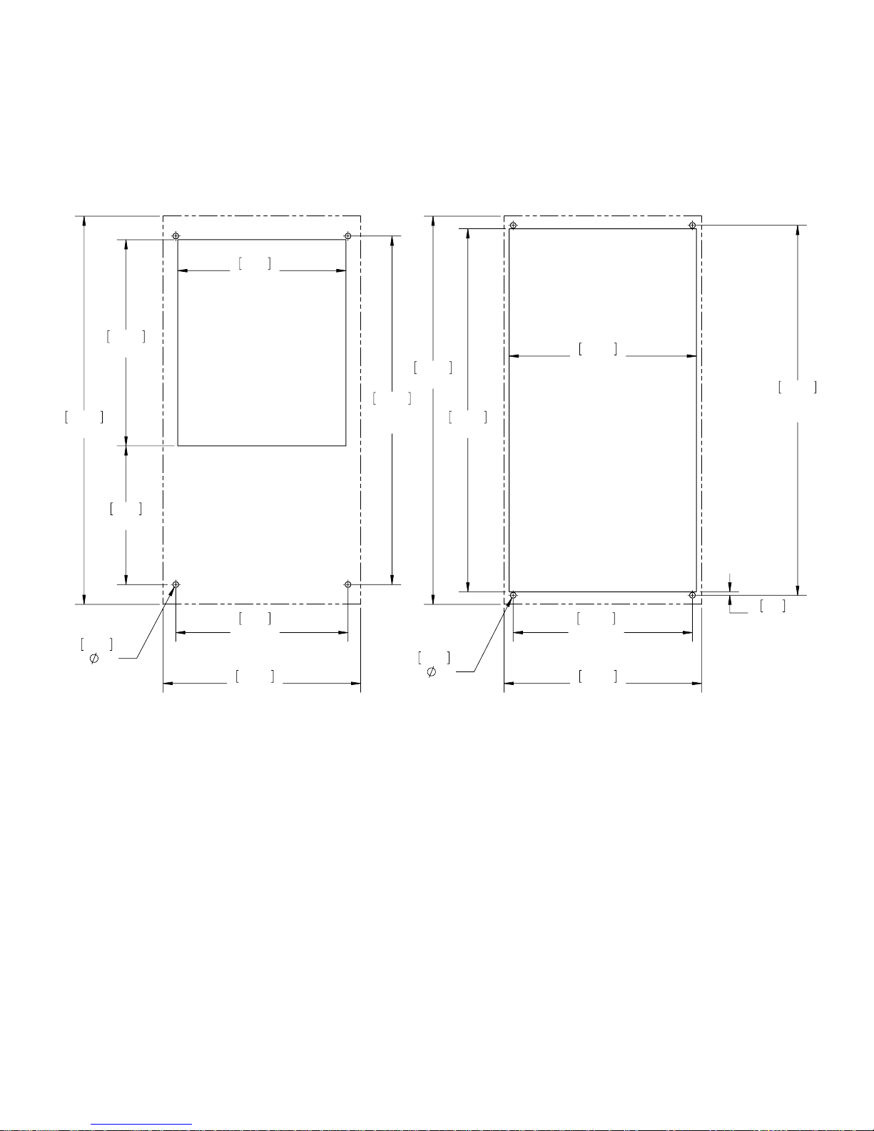
S06 INSTALLATION INSTRUCTION
1. See Receiving The Air Conditioner and Handling and Testing The Air Conditioner on page 6.
2. Using the cutout template provided with the unit, prepare the enclosure. See Figure 11 and Figure 12.
The front of the unit requires a half meter clearance for proper airflow. Five centimeters is required
on each side of the unit. To avoid condensate overflow, unit must be mounted within 3° of level.
3. Refer to mounting instructions on page 8.
4. Adjust controller to desired cabinet temperature. Refer to Displaying and Changing Program
Variables on page 13 for controller adjustment and operation.
9.38
238
21.65
550
.315
(4)
8
11.50
292
7.74
196
9.61
244
(2)
11.02
280
19.44
494
(2)
21.65
550
.315
(4)
8
20.25
514
10.44
265
10.00
254
(2)
11.02
280
20.63
524
(2)
.19
5
Surface Mount Full Recess Mount
Dashed Lines Represent The Air Conditioner
89116616
Figure 11
S06 300W Cutout Drawing
© 2015 Pentair Equipment Protection
- 19 -
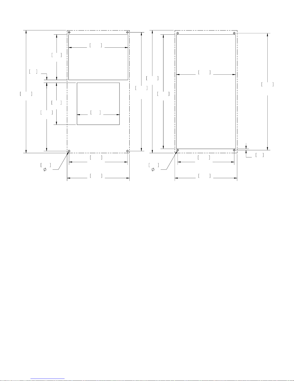
8.00
203
10.50
267
21.65
550
.50
13
12.05
306
.315
8
(4)
10.44
265
10.00
254
(2)
11.02
280
7.40
188
7.56
192
10.32
262
(2)
11.02
280
20.94
532
(2)
21.65
550
20.15
512
.315
8
(4)
Surface Mount Partial and Full Recess Mount
20.63
524
(2)
.24
6
Figure 12
S06 500W Cutout Drawing
Dashed Lines Represent The Air Conditioner
- 20 -
© 2015 Pentair Equipment Protection
89116616
 Loading...