

Pentair S060516G041, S060316G031, S060326G031, S060516G031, S060526G041 Instruction Manual
...Page 1
SPECTRACOOL™
Slim Fit Air ConditionerS
All modelS
INSTRUCTION MANUAL
Rev. I
© 2015 Pentair Equipment Protection 89116616
P/N 89116616
Page 2

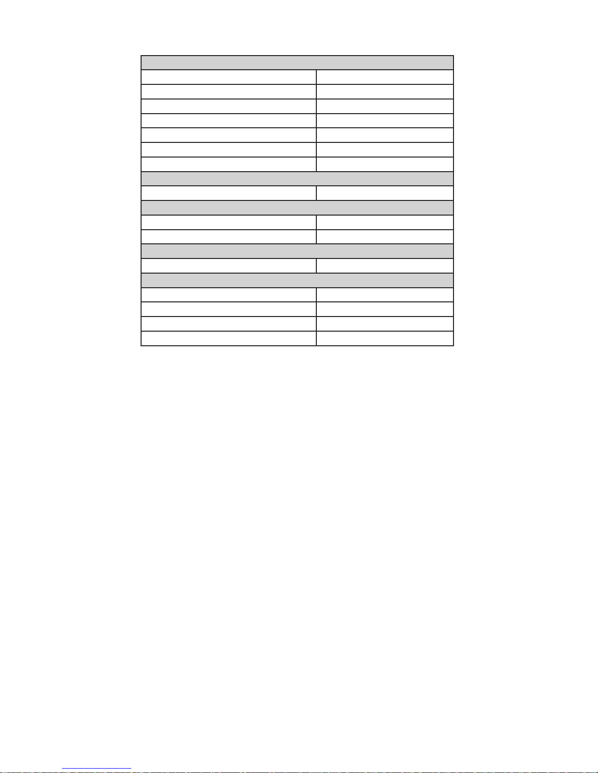
TABLE OF CONTENTS
Pentair Cooling Sales and Service Contacts ....................................................................................................4
Warranty and Return Policy ............................................................................................................................. 4
General Information ......................................................................................................................................... 5
Standards, CE, Declaration of Conformity ...........................................................................................................................5
Receiving The Air Conditioner .......................................................................................................................... 6
Handling and Testing The Air Conditioner ....................................................................................................... 6
PHASE MONITOR (460v Only) .....................................................................................................................................6
How to Read Model Numbers ........................................................................................................................... 6
General Safety Information .............................................................................................................................. 7
General Technical Information ......................................................................................................................... 7
Sequence of Operation .........................................................................................................................................................7
Cooling ............................................................................................................................................................................7
Component Operation ...........................................................................................................................................................7
Smart Controller (General Alarms)...............................................................................................................................7
Remote Access Control (Optional) ................................................................................................................................7
Door Switch ....................................................................................................................................................................7
Active Condensate Management ...................................................................................................................................7
Mounting .......................................................................................................................................................... 8
Tools Required For Installation: ...........................................................................................................................................8
External Mounting ................................................................................................................................................................8
Partial Recessed Mounting (Not Applicable to 300W Unit) .................................................................................................8
Full Recessed Mounting .....................................................................................................................................................10
Electrical Installation ..................................................................................................................................... 11
Principles of Operation .................................................................................................................................. 11
Smart Controller ............................................................................................................................................ 12
Introduction .........................................................................................................................................................................12
Energizing The Controller ..................................................................................................................................................12
Control Status Indication ....................................................................................................................................................12
Displaying and Changing Program Variables ....................................................................................................................13
Models with °C Controller ........................................................................................................................................13
Operating Parameters .................................................................................................................................................13
Alarm Parameters .......................................................................................................................................................13
Models with °F Controller ........................................................................................................................................13
Operating Parameters .................................................................................................................................................13
Alarm Parameters .......................................................................................................................................................13
Displaying Temperature Sensor #2 ...................................................................................................................................14
Compressor Restart Time Delay ........................................................................................................................................14
Alarm Output Contact .........................................................................................................................................................14
Alarm Input Connection ......................................................................................................................................................14
Alarm Condition Display .....................................................................................................................................................14
Remote Access Control .................................................................................................................................. 15
Air Conditioner Unit Communication Features (Optional) ................................................................................................15
USB Communication ....................................................................................................................................................15
Ethernet Communication ............................................................................................................................................15
SOFTWARE AND CONFIGURATION FILE DOWNLOADS .........................................................................................15
Remote Access Control Pin-out ..................................................................................................................................15
Technical Information .................................................................................................................................... 16
S06 Models 300/500W .........................................................................................................................................................16
S06 Schematic 300/500W ............................................................................................................................................16
S06 Wire Diagram 300/500W .......................................................................................................................................17
S06 Dimensional Drawings .........................................................................................................................................18
300W ..........................................................................................................................................................................18
500W ..........................................................................................................................................................................18
S06 Installation Instruction .........................................................................................................................................19
S06 300W Cutout Drawing ...........................................................................................................................................19
Surface Mount ..............................................................................................................................................................19
Full Recess Mount ........................................................................................................................................................19
S06 500W Cutout Drawing ...........................................................................................................................................20
Surface Mount ..............................................................................................................................................................20
Partial and Full Recess Mount ....................................................................................................................................20
S06 Unit Characteristics ..............................................................................................................................................21
S06 Components ..........................................................................................................................................................22
S10 Models 1000/1500W .....................................................................................................................................................23
- 2 -
© 2015 Pentair Equipment Protection
89116616
Page 3

S10 Schematics ............................................................................................................................................................23
1000W 115V, 230V .....................................................................................................................................................23
1000W 460V ...............................................................................................................................................................23
1500W 115V ..................................................................................................................................................................24
1500W 230V ..................................................................................................................................................................24
1500W 460V ..................................................................................................................................................................25
S10 Wire Diagrams ......................................................................................................................................................26
1000W 115V, 230V .....................................................................................................................................................26
1000W 460V ...............................................................................................................................................................27
1500W 115V ...............................................................................................................................................................28
1500W 230V ...............................................................................................................................................................29
1500W 460V ...............................................................................................................................................................30
S10 Dimensional Drawing ...........................................................................................................................................31
1000/1500W ..............................................................................................................................................................31
S10 Installation Instruction .........................................................................................................................................32
S10 1000/1500W Cutout Drawing ................................................................................................................................32
Surface Mount ..............................................................................................................................................................32
Partial and Full Recess Mount ....................................................................................................................................32
S10 Unit Characteristics (115V, 230V) .........................................................................................................................33
S10 Unit Characteristics (460V) ...................................................................................................................................34
S10 Components (1 Phase) ..........................................................................................................................................35
S10 Components (3 pHASE) ........................................................................................................................................36
S16 Models 2000/2500W .....................................................................................................................................................37
S16 Schematics ............................................................................................................................................................37
2000W 115V ...............................................................................................................................................................37
2000W 230V ...............................................................................................................................................................37
2000W 460V ...............................................................................................................................................................38
2500W 115V ...............................................................................................................................................................38
2500W 230V ...............................................................................................................................................................39
2500W 460V ...............................................................................................................................................................39
4000W 460V ...............................................................................................................................................................40
S16 Wire Diagrams .....................................................................................................................................................41
2000W 115V ...............................................................................................................................................................41
2000W 230V ...............................................................................................................................................................42
2000W 460V ...............................................................................................................................................................43
2500W 115V ...............................................................................................................................................................44
2500W 230V ...............................................................................................................................................................45
2500W 460V ...............................................................................................................................................................46
4000W 460V ...............................................................................................................................................................47
S16 Dimensional Drawing ...........................................................................................................................................48
2000/2500W ..............................................................................................................................................................48
4000W ........................................................................................................................................................................49
S16 Installation Instruction .........................................................................................................................................50
S16 2000/2500W Cutout Drawing ................................................................................................................................50
Surface Mount ..............................................................................................................................................................50
Partial and Full Recess Mount ....................................................................................................................................50
S16 4000W Cutout Drawing .........................................................................................................................................51
Surface Mount ..............................................................................................................................................................51
Partial Recess Mount ...................................................................................................................................................51
S16 Unit Characteristics (115V, 230V) .........................................................................................................................52
S16 Unit Characteristics (460V) ...................................................................................................................................53
S16 Components )115V, 230V) .....................................................................................................................................54
S16 Components (460V) ...............................................................................................................................................55
Maintenance ................................................................................................................................................... 56
Compressor .........................................................................................................................................................................56
Inlet Air Filter (Field Installed Option) ................................................................................................................................56
How To Remove, Clean or Install an optional Inlet Air Filter ............................................................................................56
Condenser and Evaporator Air Movers ..............................................................................................................................56
Maintenance / Inspection Recommendations ............................................................................................................57
Basic Air Conditioning Trouble Shooting Check List - Remote Access Control Version ................................. 59
Basic Air Conditioning Trouble Shooting Checklist ...........................................................................................................60
3-Phase Basic Air Conditioning Trouble Shooting Check List - Remote Access Control Version ...................................61
3-Phase Symptoms and Possible Causes - Remote Access Control Version ..................................................................62
89116616
© 2015 Pentair Equipment Protection
- 3 -
Page 4
PENTAIR COOLING SALES AND SERVICE CONTACTS
EUROPE:
Deutschland (Germany) +49 (0) 7082 794 0
France +33 (0) 3 88 90 64 90
Italia (Italy) +39 02 932 714-1
Polska (Poland) +48 22 209 98 37
Россия (Russia) +7 495 926 18 85
Sverige (Sweden) +46 (0) 8 683 6100
United Kingdom +44 (0) 1442 240 471
MIDDLE EAST:
UAE +971 4 378 1700
NORTH AMERICA:
México +52 555 280 1449
US & Canada +1 763 421 2240
SOUTH AMERICA:
Brasil (Brazil) +55 15 3363 9100
ASIA/SOUTH PACIFIC:
中国 (China) +86 400 820 1133
India +91 80 2845 4640
日本 (Japan) +81 (0) 45 476 02 81
Singapore +65 6768 5800
Or visit PentairProtect.com
WARRANTY AND RETURN POLICY
Visit www.pentairprotect.com/en/na/warranty for product warranty and return policy.
- 4 -
© 2015 Pentair Equipment Protection
89116616
Page 5

GENERAL INFORMATION
STANDARDS, CE, DECLARATION OF CONFORMITY
PENTAIRTECHNICALSOLUTIONS
Minneapolis,MN55303‐1745,USA
2100HoffmanWay
+1.763.421.2240main
DeclarationofConformity
Issued by Manufacturer
Pentair Technical Products China dba Hoffman
declare at our sole responsibility, that these devices are designed and constructed according to the fundamental safety and health
requirements of the relevant EC directives.
Equipment Description: S0603X6GXXX, S0605X6GXXX, S1010X6GXXX, S1015X6GXXX, S1620X6GXXX,
S1625X6GXXX, S1640X6GXXX
Product Name: “ SpectraCool SLIM Fit” Control Cabinet Air-Conditioner
First Year of CE Marking: 2014
Ingress Protection: IP 34 – Ambient Side, IP 54 Enclosure Side
Applicable Directives: Directive /95/EC Low Voltage Directive
Laws for electrical equipment within certain voltage limits
Directive /108/EC EMC Directive relating to
Electromagnetic compatibility
Directive /65/EU on the restriction of the use of certain hazardous substances in
electrical and electronic equipment
Applicable Standards:
EN 378-1 and -2 Refrigerating systems and heat pumps-safety and environmental
requirements
EN 12100-1 and -2 Safety of machinery, equipment and facilities
EN ISO 13857 Safety of machinery-safety distances to prevent hazard zones being
reached by upper and lower limbs
EN 60335-1 and -2-40 Appliances-Safety, Particular requirements for electrical heat
pumps, air-conditioners and dehumidifiers
DIN EN 14511-2 (4) Air conditioner, Test conditions
DIN EN 14511-3 (4) Air Conditioner, Test methods
DIN EN 14511-4 (4.2, 4.5, 4.6) Air Conditioner, operating requirements
DIN 3168-4.5 Coolers for distribution boxes, concepts testing, marking
EN 61000-6-2 Electromagnetic compatibility (EMC)- Part 6-2: Generic standards -
Immunity for industrial environments
EN 61000-6-3 Electromagnetic compatibility (EMC)- Part 6-3: Generic standards –
Emission standard for residential, commercial, and light industrial environments
EN 60529, IEC 60529 Degrees of protection provided by enclosures (IP code)
EN 50581: Technical documentation for the assessment of electrical and electronic
products with respect to the restriction of hazardous substances
DIN 45635 Measurement of noise emitted by machines, airborne noise emission
For official DoC, go to http://www.pentairprotect.com/en/na/Compliance
Air Port Industrial Zone
Shuangyuan Road South
Chengyang District
Qingdao,
Shandong 266108 China
Authorizedby:
Manager,Lab&Certifications
Subject to Change Without Notice DOC: 00001 -A
89116616
7/15/2014
Tom Hurney Date
© 2015 Pentair Equipment Protection
- 5 -
Page 6
RECEIVING THE AIR CONDITIONER
Inspect the air conditioner. Check for concealed damage that may have occurred during shipment. Look for dents,
scratches, loose assemblies, evidence of oil, etc. Damage evident upon receipt should be noted on the freight bill.
Damage should be brought to the attention of the delivering carrier -- NOT to Pentair Equipment Protection -within 15 days of delivery. Save the carton and packing material and request an inspection. Then file a claim with
the delivering carrier.
Pentair Equipment Protection cannot accept responsibility for freight damages; however, we will assist you in any
way possible.
HANDLING AND TESTING THE AIR CONDITIONER
If the air conditioner has been in a horizontal position, be certain it is placed in an upright, vertical or mounting
position for a minimum of five (5) minutes before operating.
CAUTION
Do not attempt to operate the air conditioner while it is horizontal or
on its side, back or front. The refrigeration compressor is filled with
lubricating oil. This will cause permanent damage to the air conditioner
and also voids the warranty.
TEST FOR FUNCTIONALITY BEFORE MOUNTING THE AIR CONDITIONER TO THE ENCLOSURE.
Refer to the nameplate for proper electrical current requirements, and then wire the unit to a properly grounded
power supply using copper conductors only. Power supply wiring should be restrained after field installation to
ensure no contact with internal fan. Minimum circuit ampacity should be at least 125% of the amperage shown on
the unit nameplate. No other equipment should be connected to this circuit to prevent overloading.
Electrical circuit should be fused with slow blow or heating, air conditioning and refrigeration (HACR) rated circuit
breaker. Use a higher ampere rated circuit breaker or time-delay fuse that is closest to the nominal ampere
rating of the air conditioner, or sum of the individual component ampere ratings, to protect system electrical
circuits from short circuit or overload.
PHASE MONITOR (460V ONLY)
Note Location: Rear access panel, D-shaped sight port.
Reference S10 Dimensional Drawing on page 31; S16 Dimensional Drawing,
2000/2500W on page 48; S16 Dimensional Drawing, 4000W on page 49
This product is equipped with Phase/Voltage Protection. Please verify correct phasing and voltage before
operating. Note the fans may still operate if phasing is incorrect, but the compressor will not, so the unit
will not cool. Illuminated light on Phase Monitor indicates phase is correct.
If the light is not illuminated, disconnect power from the unit and swap any two power leads at the
terminal block. This should correct the phasing. The light should now illuminate when power is reapplied.
Immediately after applying power, the evaporator blower (enclosure air) should start running. Operate the air
conditioner with the compressor running for five (5) to ten (10) minutes. You will need to set the cooling controller
setpoint below the ambient temperature to operate the compressor.
Condenser air temperatures should be warmer than normal room temperatures within a few minutes after the
condenser impellers start.
See Sequence of Operation on page 7 for specifics on how the unit operates when powered up.
HOW TO READ MODEL NUMBERS
S10 15 2 6 G031
1 2 3 4 5
1. Identifies the type/family of air conditioner and the approximate height (i.e. S10 = Slim Fit family
about 1000mm high (10x100).
2. This is the air conditioner’s listed capacity in Watts at rated conditions. (i.e. 15=1500W (15x100) at
35/35 C)
3. 1 = 115 Volt, 2 = 230 Volt, 4 = 400/460 Volt.
4. 5 = 50 Hz only, 6 = 50/60 Hz or 60 Hz only.
5. Unique set of numbers for each air conditioner which identifies the accessories on a model.
- 6 -
© 2015 Pentair Equipment Protection
89116616
Page 7

GENERAL SAFETY INFORMATION
Please observe the following general safety instructions when assembling and operating the unit:
• Assembly,installation and servicing may only be performed by properly trained specialists.
• When transporting the enclosure with the cooling unit externally mounted, always use an additional shipping brace
to support the cooling unit.
GENERAL TECHNICAL INFORMATION
The evaporator outlet sensor monitors the enclosure return air temperature to prevent ice buildup on the
evaporator coil. If the air temperature drops below -1°C, the compressor and condenser air mover(s) shut off.
They turn back on when the temperature rises above 15°C.
The compressor and the air movers are equipped with overload protection to guard against excess current and
temperatures.
SEQUENCE OF OPERATION
The air conditioner comes standard with smart controller. During cooling modes, the evaporator fan will be
running.
COOLING
When the enclosure temperature is above the cooling setpoint, power is applied to the compressor and
condenser air mover(s).
Operating the air conditioner below the minimum ambient temperature or above the maximum
ambient temperatures indicated on the nameplate voids all warranties. DO NOT adjust the setpoint to a
temperature lower than 20°C. Doing so can increase the likelihood of frost buildup on the evaporator coil.
The moisture that the sealed enclosure air can contain is limited. If moisture flows from the drain tube
continuously this can only mean that ambient air is entering the enclosure. Be aware that frequent
opening of the enclosure’s door admits humid air that the air conditioner must then dehumidify.
COMPONENT OPERATION
NOTE: Do not reduce the time delay setting on the controller to less than 120 seconds. This may
cause the compressor to cycle too rapidly, shortening the life of the compressor.
SMART CONTROLLER (GENERAL ALARMS)
See Smart Controller on page 12
REMOTE ACCESS CONTROL (OPTIONAL)
See Remote Access Control on page 15
DOOR SWITCH
Several door switches may be connected in series and operated on one cooling unit. The door switch
only supports a floating connection, no external voltages. Remove jumper from terminals 3 and 4 of the
connector and connect the door switch to the two terminals if a door switch is available.
NOTE: The alarm code “TP” will appear on the controller display if this jumper wire is removed
without the addition of a customer installed door switch.
ACTIVE CONDENSATE MANAGEMENT
At low temperatures and high humidity levels inside the enclosure, condensation may form on the
evaporator coil.
Slim Fit air conditioners continuously evaporate the water that may be in the drain pan due to
condensation from the evaporator coil into the external air stream. Excess condensate is routed
downwards out of the air conditioner via a barbed fitting at the bottom of the condenser side of the unit. A
10 mm (.40) inside diameter tube can be attached to the fitting and routed to a nearby drain.
89116616
© 2015 Pentair Equipment Protection
- 7 -
Page 8
MOUNTING
TOOLS REQUIRED FOR INSTALLATION:
• #2 Phillips screwdriver
• 6.5 mm slotted screwdriver
• 13 mm wrench or socket
EXTERNAL MOUNTING
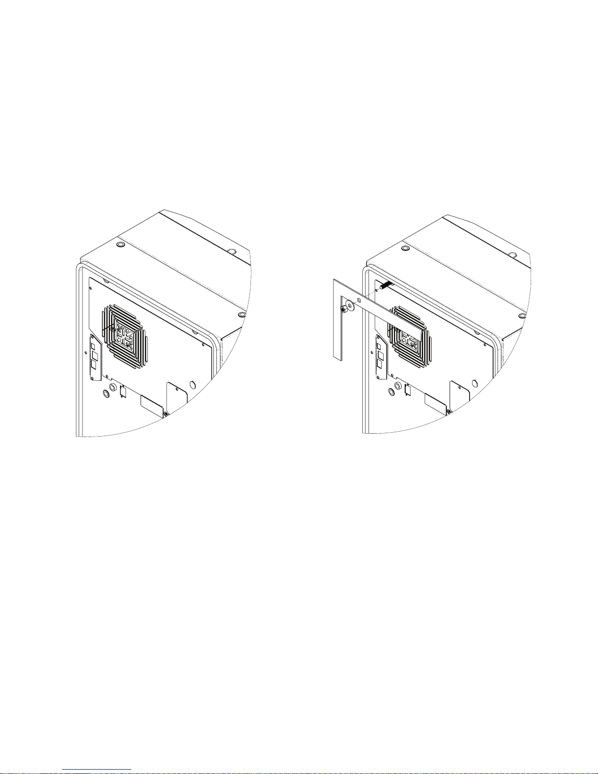
1. Using the mounting gasket kit provided with the unit, install gasket to the air conditioner, see Figure
1.
2. Screw the supplied grub screws into the blind nuts on the rear of the unit, see Figure 2.
3. Secure the unit to the enclosure using the supplied washers and nuts. Use caution to avoid damaging
the gasket while positioning the unit.
Figure 1 Figure 2
PARTIAL RECESSED MOUNTING (NOT APPLICABLE TO 300W UNIT)
1. Carefully remove the louvered grille, and where applicable, remove the center panel from the
enclosure by pulling forwards. See Figure 3 on page 9.
2. Carefully disconnect the connectors from the rear of the smart controller.
3. Remove the two front screws.
4. Remove the four nuts on the front panel and pull the panel assembly forward approximately 5 cm.
See Figure 4 on page 9.
5. Disconnect the fan electrical connection.
6. Remove the front panel.
7. Remove the four standoffs, leaving the grub screws in place.
8. Push the rear enclosure half into the mounting cutout and secure it with the four standoffs. See
Figure 5 on page 9.
9. Push the smart controller cables through the rectangular hole in the front panel.
10. Reconnect the fan electrical connector.
11. Mount the front panel using the nuts removed in step 4.
12. Install two front screws.
13. Carefully reconnect the smart controller connectors .
14. Push the louvered grille and, where applicable, the center panel, onto the front panel. See Figure 6
on page 9.
- 8 -
© 2015 Pentair Equipment Protection
89116616
Page 9
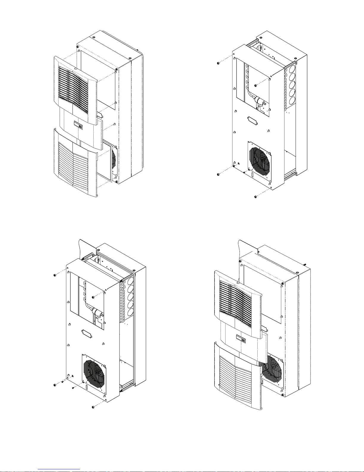
Figure 3
Figure 4
Figure 5 Figure 6
89116616
© 2015 Pentair Equipment Protection
- 9 -
Page 10
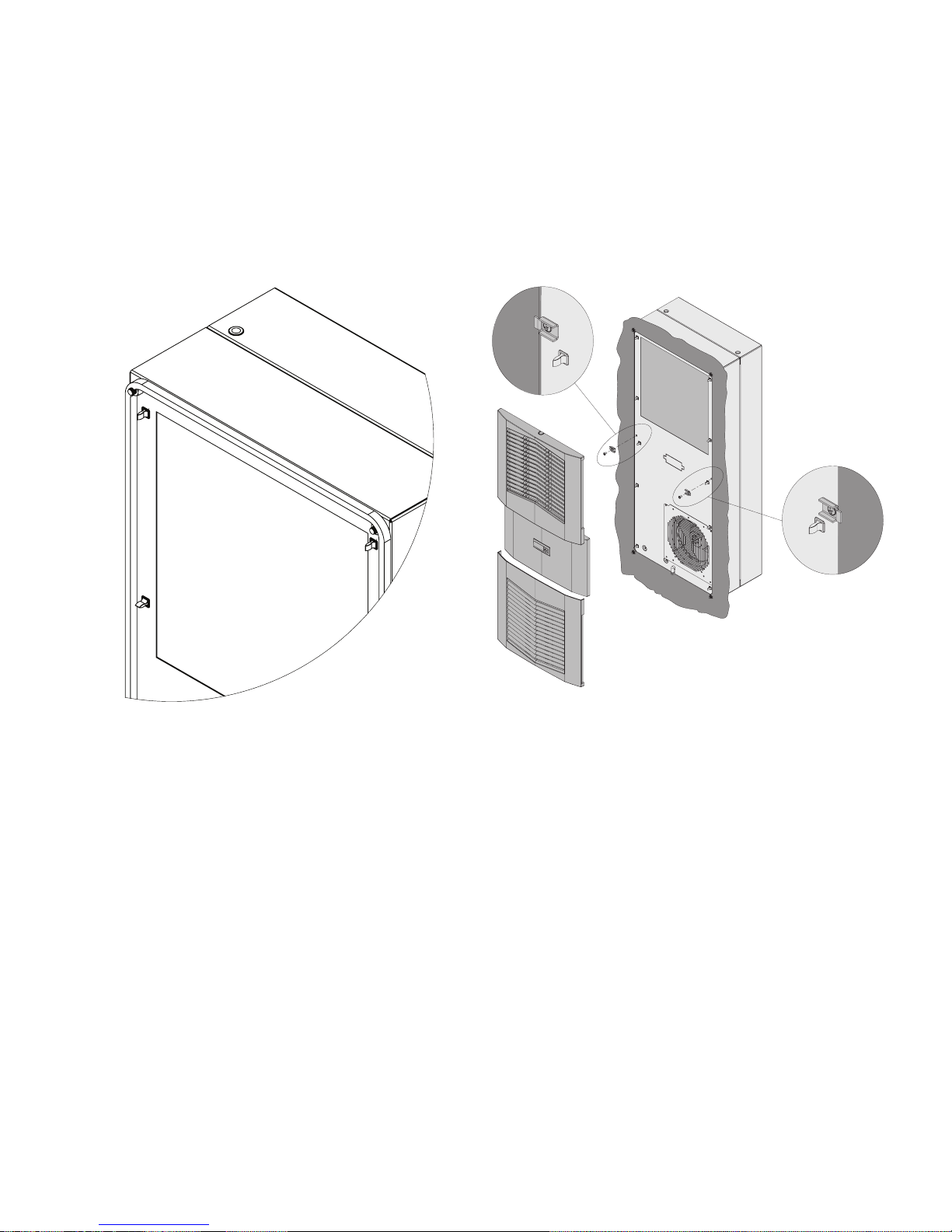
FULL RECESSED MOUNTING
1. Carefully remove the louvered grille, and where applicable, remove the center panel from the
enclosure by pulling forwards.
2. Carefully disconnect the connectors from the rear of the smart controller.
3. Using the mounting gasket kit provided with the unit, install gasket to the air conditioner front panel.
See Figure 7.
4. Remove the four nuts on the front panel.
5. Push the unit into the mounting cutout and secure it using the nuts removed in step 4.
6. Carefully reconnect the smart controller.
7. Push the louvered grille and, where applicable, the center panel, onto the front panel. See Figure 8.
- 10 -
Figure 7
© 2015 Pentair Equipment Protection
Figure 8
89116616
Page 11
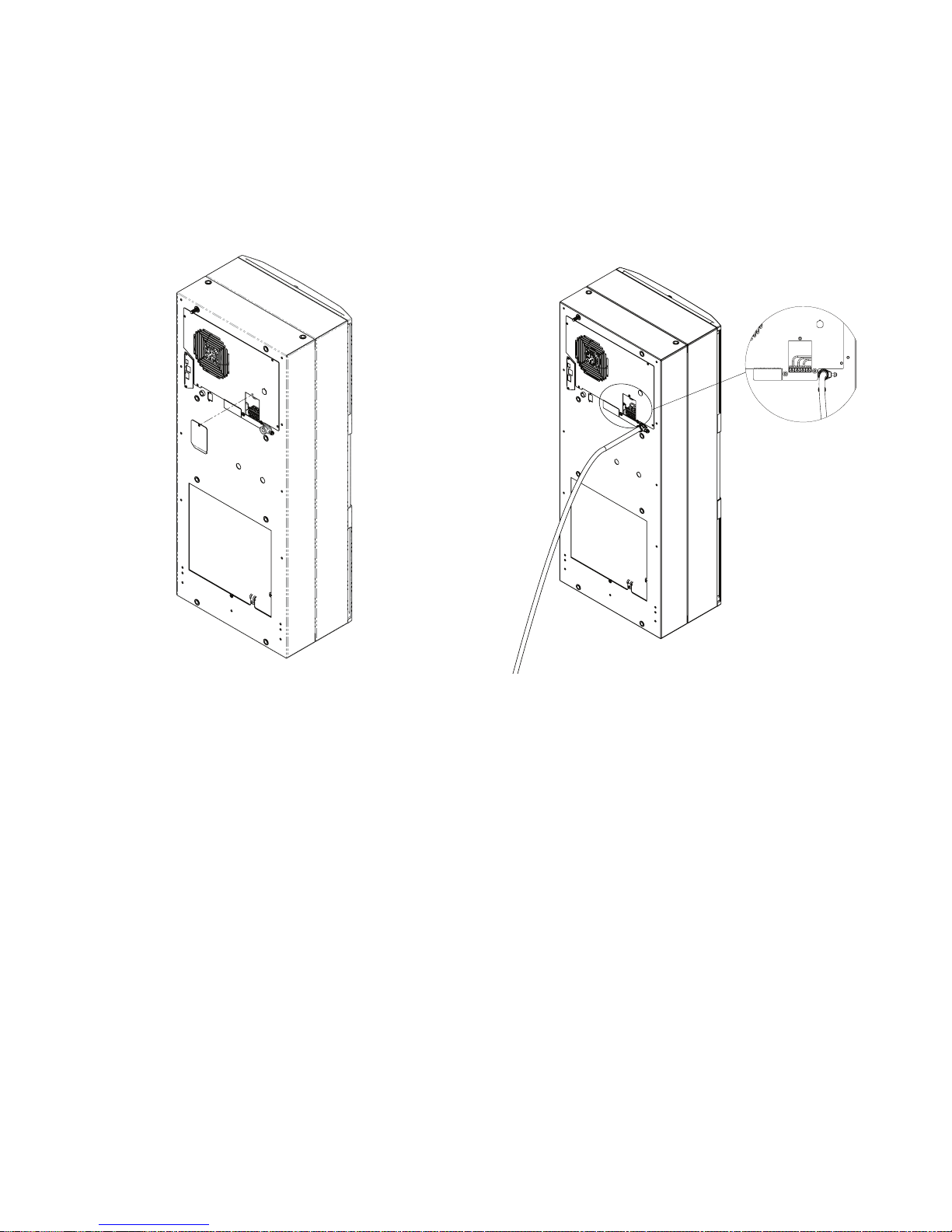
ELECTRICAL INSTALLATION
1. Loosen the screw on the evaporator access panel and remove the power access panel. See Figure 9.
2. Push the power supply wire through the strain relief.
3. Connect the wire to the terminal block per the label.
4. Reinstall the power access panel and screw.
5. Tighten the screw on the strain relief to secure the supply wire, see Figure 10.
NOTE: Use a higher ampere rated circuit breaker, or time-delay fuse, that is closest to the
nominal ampere rating of the air conditioner, or sum of the individual component ampere ratings,
to protect the system electrical circuits from short circuit or overload.
Figure 9
Figure 10
PRINCIPLES OF OPERATION
If electrical power to the air conditioner is interrupted and reapplied, the compressor may take up to five (5)
minutes to restart due to the high back pressure of the compressor.
NOTE: The controller includes a nominal time delay setting of 5 minutes. Do not decrease the
time delay setting to less than 2 minutes, as this may cause rapid cycling of the compressor,
which may reduce the life of the compressor.
89116616
© 2015 Pentair Equipment Protection
- 11 -
Page 12
SMART CONTROLLER
INTRODUCTION
The smart controller is a parametric controller for the complete management of air conditioners. All settings are
pre-programmed at the factory. Cooling set-points, cooling differential and high/low temperature alarm setpoints can be adjusted by the user. Alarms are outputted through a relay contact.
NOTE: The polyester tape on the top side and the neoprene seal around the connectors
assure IP34 protection for the controller. Do not remove.
ENERGIZING THE CONTROLLER
The controller is wired and programmed at the factory to be energized when power is applied to the air
conditioner.
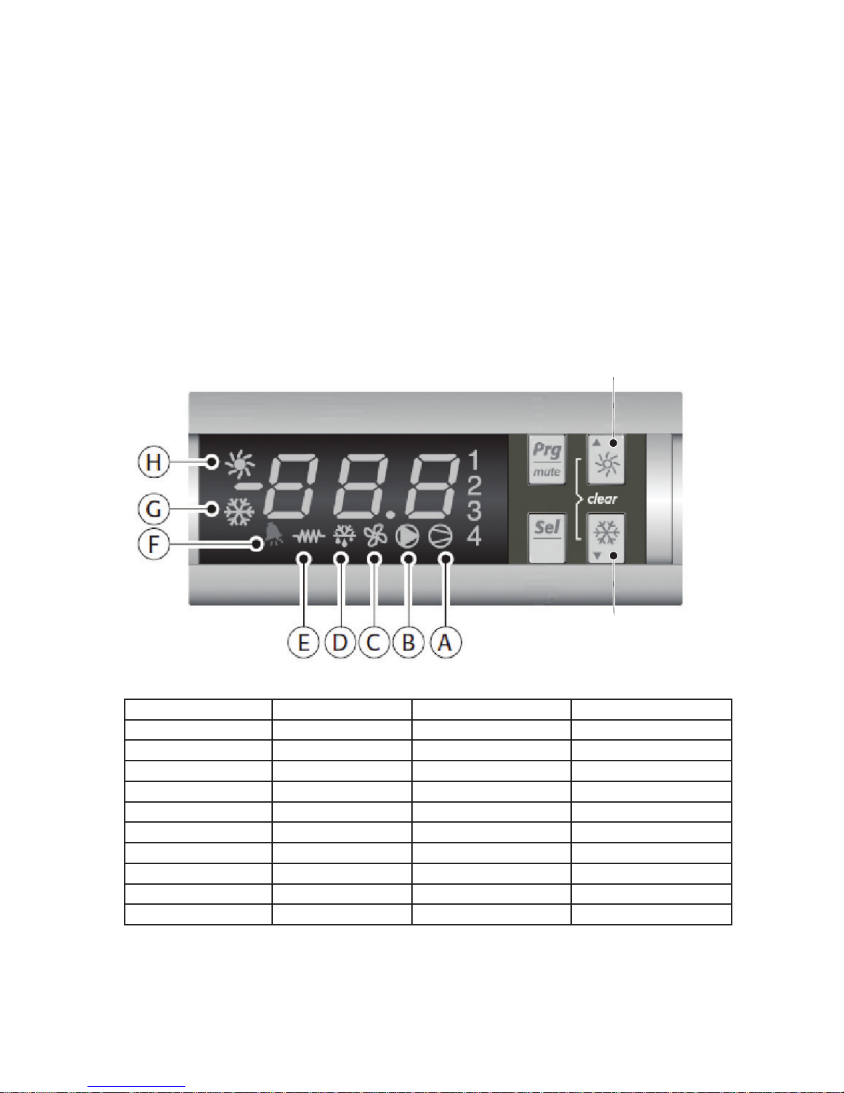
CONTROL STATUS INDICATION
The display has numerous symbols that indicate if the controller is heating, cooling, alarming, if the compressor
is enabled, and if the ambient fan is enabled. The 3 alpha-numeric characters further describe alarms and show
the cabinet temperature by default.
NOTE: The Slim Fit air conditioners do not come standard with a heating option.
Heating (sun)
Cooling
(snowake)
SYMBOL COLOR ICON ON ICON FLASHING
1 AMBER Compressor On Start-up Request
2,3,4 AMBER Not Used Not Used
A AMBER Compressor On Not Used
B AMBER Evaporator Fan On Not Used
C AMBER Not Used Not Used
D AMBER Not Used Not Used
E AMBER Not Used Not Used
F RED Alarm Active Not Used
G AMBER Controller Active Not Used
H AMBER Not Used Not Used
NOTE: On the smart controller, the display symbols for “H” and “E” are not suppose to
turn ON. If they do turn on, simply hold the “Heating” button for 5 seconds to disable
them. Then hold the “Cooling” button for 5 seconds until the snowflake symbol (“G”)
displays.
- 12 -
© 2015 Pentair Equipment Protection
89116616
Page 13

DISPLAYING AND CHANGING PROGRAM VARIABLES
Access: To view and/or change parameters, press and hold the Prg and Sel buttons for greater than 5 seconds.
Press the up or down arrow buttons until 22 is displayed, then press Sel button. When S-P is displayed, press Sel.
Navigation: Press up or down arrows to display sub-menus then press Sel to select the desired sub-menu. In the
sub-menu, use up or down arrows to display parameters for viewing or changing and press Sel. Use Prg button to
back out of menu levels as desired.
Adjust: Use the up or down arrows to change the parameter value then push Sel to save that setting. If Sel is not
pressed, the change to the value will not be saved. Navigate to and change other parameters as desired. When
finished, push Prg to back out of the sub-menus to the main menu.
NOTE: The display will revert to normal temperature display mode if no buttons are pressed for
60 seconds.
MODELS WITH °C CONTROLLER
Cooling turns on at r01 (Setpoint), and off at r01 (Setpoint) - r02 (Differential).
For example, using default values from the table below, cooling will turn on at 35 °C (setpoint), and turn
off at 30 °C (setpoint – differential).
OPERATING PARAMETERS
Parameter Description Default Value Range
r01 Cooling set-point 35°C 20°C to 55°C
r02 Cooling differential 5°C -
ALARM PARAMETERS
Parameter Default Value Range Description
P16 55°C - High Temperature Alarm
P19 14°C - Low Temperature Alarm
MODELS WITH °F CONTROLLER
Cooling turns on at r01 (Setpoint) + r02 (Differential), and off at r01 (Setpoint).
For example, using default values from the table below, cooling will turn on at 87 °F (setpoint +
differential), and turn off at 80 °F (setpoint).
OPERATING PARAMETERS
Parameter Description Default Value Range
r01 Cooling set-point 80°F 72°F to 120°F
r02 Cooling differential 7°F -
ALARM PARAMETERS
Parameter Default Value Range Description
P16 125°F - High Temperature Alarm
P19 40°F - Low Temperature Alarm
89116616
© 2015 Pentair Equipment Protection
- 13 -
Page 14

DISPLAYING TEMPERATURE SENSOR #2
Sensor number 2, the air outlet or evaporator coil sensor, can be viewed at any time by pressing the up or down
arrow button on the front panel of the controller display. The display will revert to displaying temperature sensor
number 1 (the evaporator air inlet temperature) after 60 seconds. Both sensors can also be read through the
Ethernet and USB connections with the optional communications board.
COMPRESSOR RESTART TIME DELAY
A factory set 5 minute (300 second) restart delay exists to reduce residual back pressure before allowing the
compressor to restart. The compressor will stay off for the entire restart duration after the compressor is
disabled. A flashing 1 on the controller display will indicate the unit is in a compressor restart delay while calling
for cooling. If the time delay is reduced to less than five (5) minutes, this may cause reduced compressor life.
ALARM OUTPUT CONTACT
The smart controller has a normally open dry contact alarm output with a resistive load rating of 250 VAC at 3
amps. A connector located on the enclosure side of the unit provides a 2 pin connection to this output marked
YEL/ALARM.
ALARM INPUT CONNECTION
The smart controller can accept a dry contact/switch input via the connector terminals marked WHT/DS1 and
WHT/DS2 located on the enclosure side of the unit. This input is associated with the controller display alarm
mnemonic TP (door open and/or smoke detected). To use this feature, remove the jumper wire connecting
terminals DS1 and DS2 and replace with customer supplied wires from the enclosure door switch to DS1 and DS2
terminals.
ALARM CONDITION DISPLAY
There are seven possible non-latching alarm conditions detectable by the controller and are indicated on the
controller display. All alarms can also be accessed through the Ethernet and USB connections with the optional
communications board.
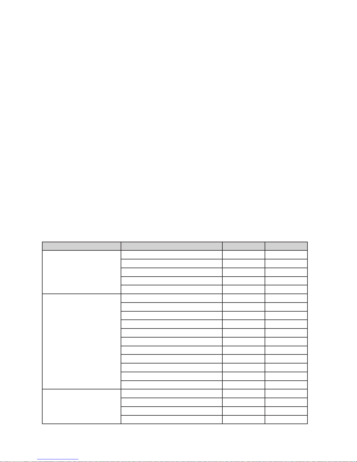
Alarm Mnemonic Description Cause Result Alarm Relay
TP General Alarm
LA High Pressure Warning
E1
E2
Ht
Lt
A1 Frost Alarm
NOTE 1: Air inlet temperature sensor will default to air outlet temperature sensor. Cooling set point defaults to 10°C.
NOTE 2: Unit continues to operate without evaporator freeze protection.
NOTE 3: The MALF high pressure switch is optional.
Air Inlet Temperature
Sensor Alarm
Air Outlet Temperature
Sensor Alarm
High Temperature Alarm
Default = 55°C
Low Temperature Alarm
Default = 14°C
Door open and/or smoke
detected
MALF high pressure
switch opens (See Note 3
below)
Sensor Failure See Note 1 below Relay Contacts Close
Sensor Failure See Note 2 below Relay Contacts Close
Air inlet temperature
greater than 55°C
Air inlet temperature less
than 14°C
Air outlet temperature
less than or equal to
-1.0°C
Unit turns off for duration
of alarm
No effect on function N/A
No effect on function Relay Contacts Close
No effect on function Relay Contacts Close
Compressor and
Condenser fan off for
duration of alarm
Relay Contacts Close
Relay Contacts Close
- 14 -
© 2015 Pentair Equipment Protection
89116616
Page 15
REMOTE ACCESS CONTROL
AIR CONDITIONER UNIT COMMUNICATION FEATURES (OPTIONAL)
An optional communication board offers capabilities that include SNMP, EtherNet/IP, Modbus TCP and Profinet
protocols through Ethernet and Modbus RTU protocol via USB. Pentair has a PC Interface Tool available for
download that can utilize either mode to communicate with the air conditioner unit.
USB COMMUNICATION
This communication mode allows direct connection of a PC to the air conditioner unit. The protocol
supported is Modbus RTU. Use the Pentair AC monitor to communicate with the air conditioner unit. A
MINI-b USB connection is included with this option.
ETHERNET COMMUNICATION
This communication mode allows remote connection to the air conditioner unit using SNMP, EtherNet/IP
and Modbus/TCP, and Profinet protocols. Customers using their own software can download a MIB file for
SNMP, EDS file or EtherNet_IP Object file for EtherNet/IP, Coil Register file for Modbus TCP and GSDML
file for Profinet.
Note: ACU has a default IP Address of 192.168.1.2
Both Ethernet and USB communication modes allow the ability to:
• Read ACU inlet and outlet air temperatures
• Read and change Cooling Set-point and Cooling Differential
• Read and change High and Low Temperature Alarm Settings
• Read and change Gateway IP Address, Device IP Address, Subnet Mask, Trap IP Address and SNMP Community
• Read and change Unit Identification
• Read and change the type of IP addressing (static or dynamic)
• Read current Alarm Status
• Read MAC address
SOFTWARE AND CONFIGURATION FILE DOWNLOADS
The Pentair AC monitor, MIB file, EDS file, EtherNet_IP Object file, Coil Register file and GSDML file for
Profinet can be downloaded from www.pentairprotect.com/en/na/Product-EnclosureCoolingHeating.
REMOTE ACCESS CONTROL PINOUT
U1 OUTPUTS
U2 INPUTS
U3 DATA
FUNCTION NAME PIN #
COOL No1 1
C1/2 2
C1/2 3
ALARM RELAY OUTPUT No5 12
C5 6
ENCLOSURE DOOR SWITCH ID1 8
MALFUNCTION NC SWITCH ID2 1
NA ID3 (na) 9
NA ID4 (na) 2
DIGITAL INPUT GROUND ID GND 3
T1, EVAP IN THERMISTOR B1 13
T2, EVAP OUT THERMISTOR B2 12
T1, T2 GND GND 6
NA B3 11
CONTROLLER POWER G 7
CONTROLLER POWER G0 14
POWER 1
GROUND 2
DIRECTION 3
DATA 4
89116616
© 2015 Pentair Equipment Protection
- 15 -
Page 16
TECHNICAL INFORMATION
S06 MODELS 300/500W
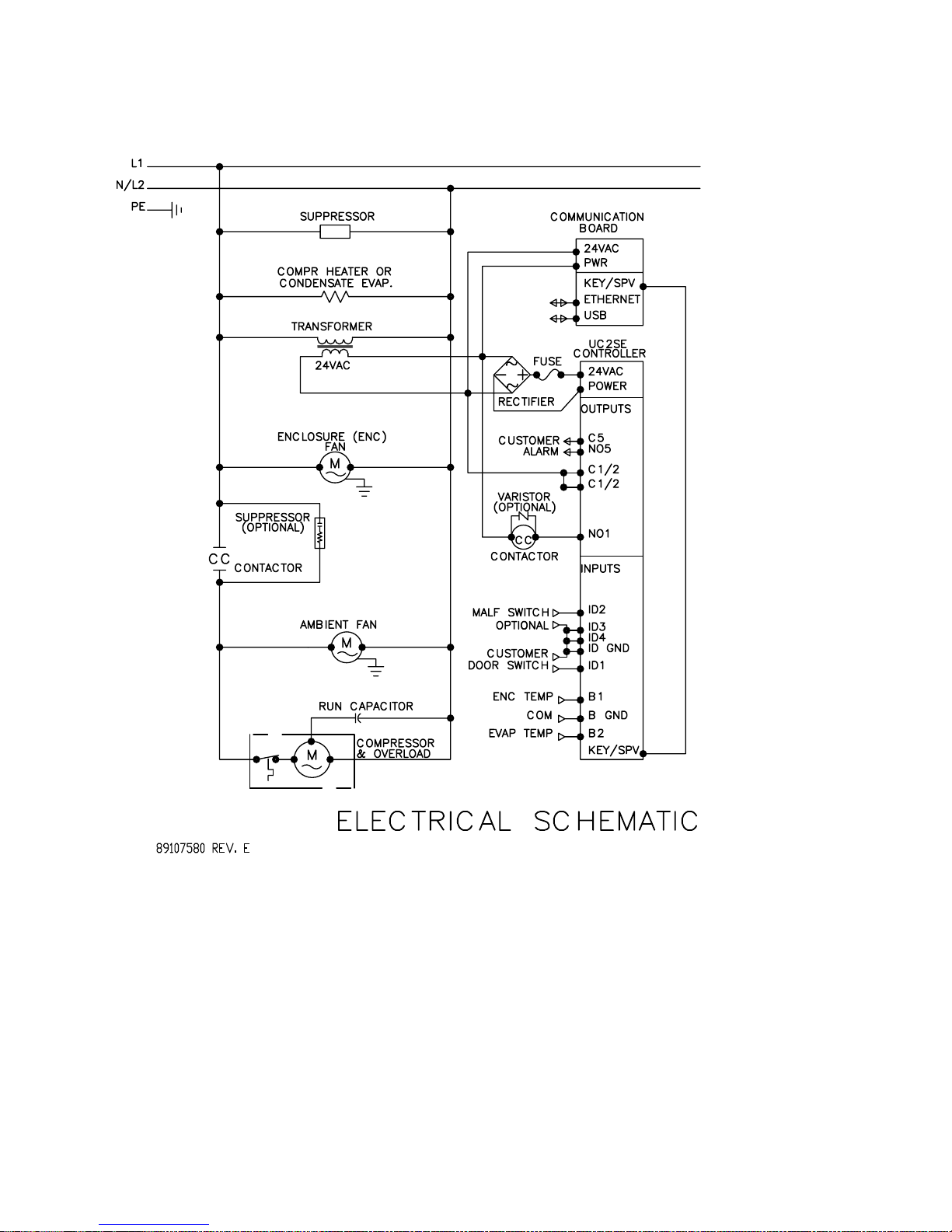
S06 SCHEMATIC 300/500W
- 16 -
© 2015 Pentair Equipment Protection
89116616
Page 17

S06 WIRE DIAGRAM 300/500W
89116616
© 2015 Pentair Equipment Protection
- 17 -
Page 18
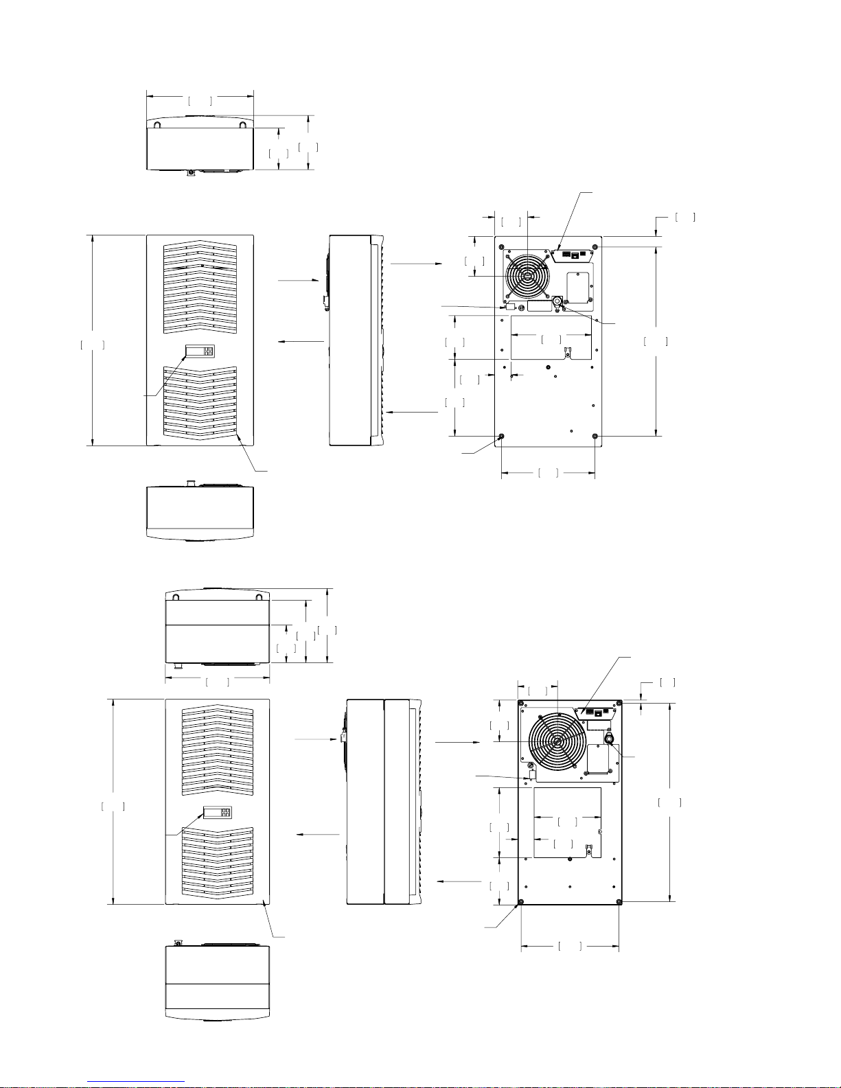
S06 DIMENSIONAL DRAWINGS
300W
280
11.02
108
4.27
5.57
142
3.39
OPTIONAL COMMUNICATION
86
BOARD CONNECTIONS
1.10
28
(2)
550
21.65
ELECTRONIC
CONTROLLER
500W
280
11.02
WARM
ENCLOSURE
AIR IN
COOL
AIR OUT
OPTIONAL FIELD-INSTALLED,CLEANABLE
REUSABLE, ALUMINUM INLET FILTER MOUNTS
BEHIND PLASTIC LOUVER
199
167
7.82
6.58
101
3.97
AIR OUT
ENCLOSURE DOOR
SWITCH SHUT DOWN
AND ALARM OUTPUT
CONNECTOR
114
4.50
M6 MOUNTING
THREADS(4)
200
7.88
AMBIENT
AIR IN
1.70
105
4.13
210
8.25
43
244
9.61
(2)
107
4.20
INPUT
494
POWER
19.44
(2)
OPTIONAL COMMUNICATION
BOARD CONNECTIONS
9
.35
(2)
550
21.65
ELECTRONIC
CONTROLLER
- 18 -
ENCLOSURE
AIR IN
COOL
AIR OUT
OPTIONAL FIELD-INSTALLED,CLEANABLE
REUSABLE, ALUMINUM INLET FILTER MOUNTS
BEHIND PLASTIC LOUVER
© 2015 Pentair Equipment Protection
WARM
AIR OUT
ENCLOSURE DOOR
SWITCH SHUT DOWN
AND ALARM OUTPUT
CONNECTOR
AMBIENT
AIR IN
M6 MOUNTING
THREADS(4)
112
4.40
188
7.40
127
5.00
1.73
179
7.06
44
10.32
262
INPUT
POWER
532
20.94
(2)
(2)
89116616
Page 19
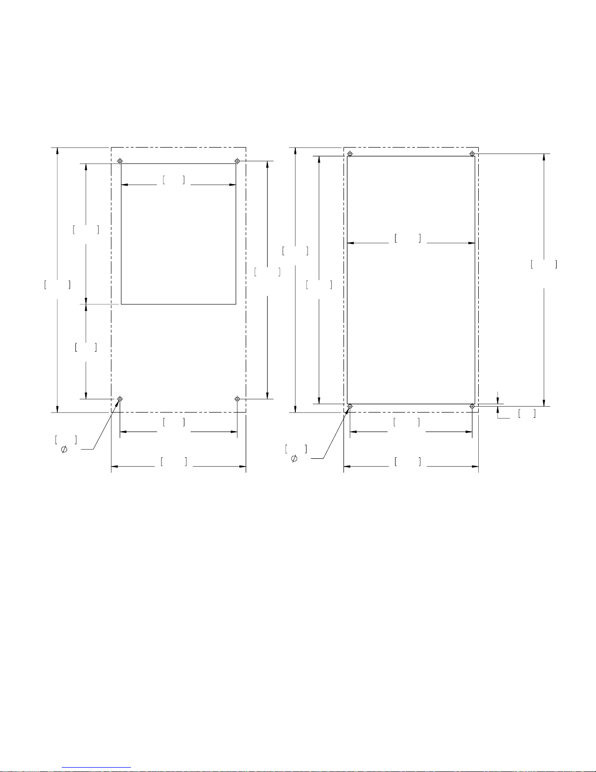
S06 INSTALLATION INSTRUCTION
1. See Receiving The Air Conditioner and Handling and Testing The Air Conditioner on page 6.
2. Using the cutout template provided with the unit, prepare the enclosure. See Figure 11 and Figure 12.
The front of the unit requires a half meter clearance for proper airflow. Five centimeters is required
on each side of the unit. To avoid condensate overflow, unit must be mounted within 3° of level.
3. Refer to mounting instructions on page 8.
4. Adjust controller to desired cabinet temperature. Refer to Displaying and Changing Program
Variables on page 13 for controller adjustment and operation.
9.38
238
21.65
550
.315
(4)
8
11.50
292
7.74
196
9.61
244
(2)
11.02
280
19.44
494
(2)
21.65
550
.315
(4)
8
20.25
514
10.44
265
10.00
254
(2)
11.02
280
20.63
524
(2)
.19
5
Surface Mount Full Recess Mount
Dashed Lines Represent The Air Conditioner
89116616
Figure 11
S06 300W Cutout Drawing
© 2015 Pentair Equipment Protection
- 19 -
Page 20
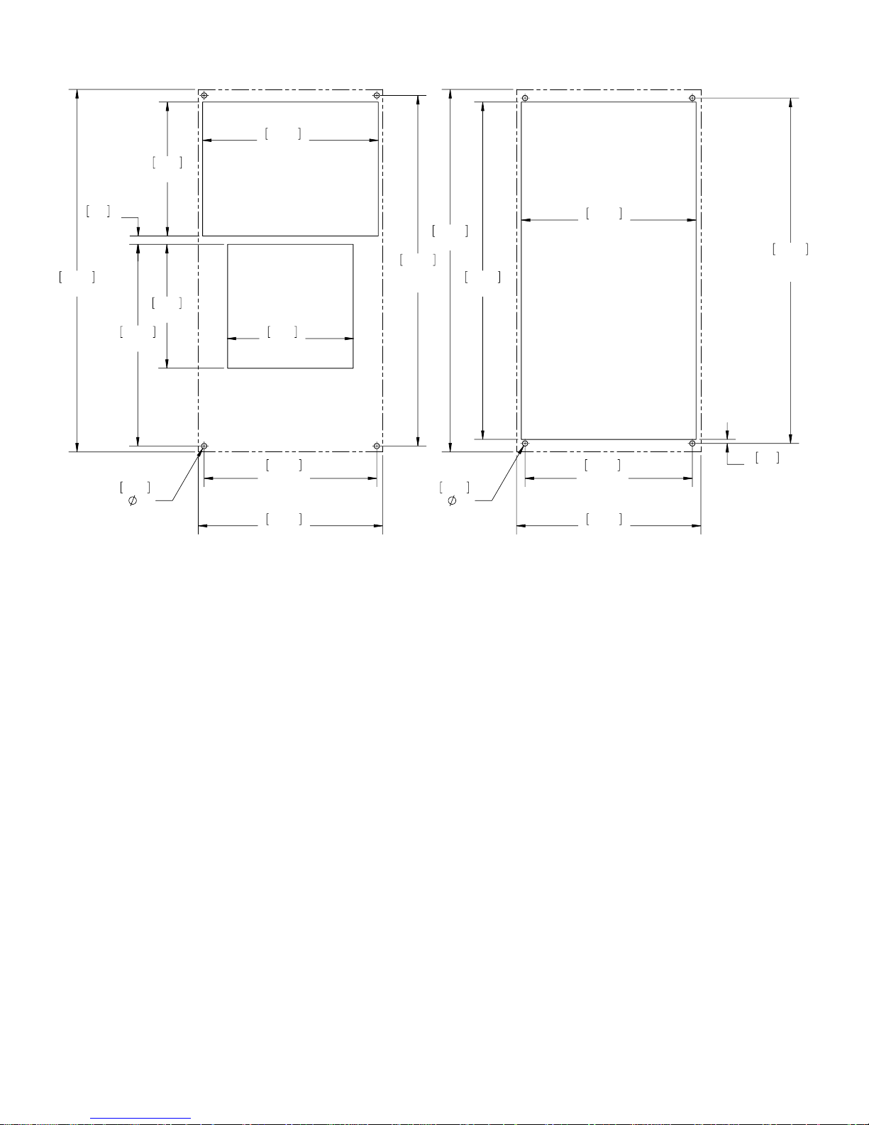
8.00
203
10.50
267
21.65
550
.50
13
12.05
306
.315
8
(4)
10.44
265
10.00
254
(2)
11.02
280
7.40
188
7.56
192
10.32
262
(2)
11.02
280
20.94
532
(2)
21.65
550
20.15
512
.315
8
(4)
Surface Mount Partial and Full Recess Mount
20.63
524
(2)
.24
6
Figure 12
S06 500W Cutout Drawing
Dashed Lines Represent The Air Conditioner
- 20 -
© 2015 Pentair Equipment Protection
89116616
Page 21

S06 UNIT CHARACTERISTICS
UNIT 300W 115V 300W 230V 500W 115V 500W 230V
CATALOG NUMBER
Indoor Model without Communications Board (°C Controller) S060316G031 S060326G031 S060516G031 S060526G031
Indoor Model with Communications Board (°C Controller) S060316G041 S060326G041 S060516G041 S060526G041
Indoor Model without Communications Board (°F Controller) S060316G050 S060326G050 S060516G050 S060526G050
Indoor Model with Communications Board (°F Controller) S060316G060 S060326G060 S060516G060 S060526G060
COOLING PERFORMANCE
Total L35 L35, 50Hz, according to DIN EN 14511 (Watt) 370 370 550 550
Cooling performance L35 L35 (Watt) 50/60Hz 370 / 420 370 / 420 550 / 640 550 / 640
Cooling performance L35 L50 (Watt) 50/60Hz 190 / 230 190 / 230 320 / 380 320 / 380
Refrigerant R134a R134a R134a R134a
Refrigerant Charge (g) 133 128 162 162
Max. allowable operating pressure (p. max.) bar 28 28 28 28
Operating Temperature Range (Min/Max °C)
Operating Temperature Range (Min/Max °F)
Setting Temperature Range (Min. / Max. °C Controller ) 20 / 55 20 / 55 20 / 55 20 / 55
Setting Temperature Range (Min. / Max. °F Controller) 72 / 120 72 / 120 72 / 120 72 / 120
Airflow at 0 Static Pressure:
Internal loop (m³/h) 109 / 124 109 / 124 197 / 233 197 / 233
External loop (m³/h) 129 / 156 129 / 156 189 / 219 189 / 219
Duty Cycle 100% 100% 100% 100%
ELECTRICAL DATA
Rated Voltage (Volt) 100 / 115 230 115 230
Phase 1~ 1~ 1~ 1~
Frequency (Hz) 50/60 50/60 50/60 50/60
Operating Range +/- 10% +/- 10% +/- 10% +/- 10%
Max power Consumption 50/60Hz L35 L35 (Watt) 270 / 300 300 / 320 450 / 470 450 / 480
Max power Consumption 50/60Hz L35 L50 (Watt) 280 / 320 330 / 350 490 / 540 510 / 540
Max. Nominal Current (Amps) 4.0 / 3.8 1.8 / 1.7 6.5 / 6.1 2.6 / 2.9
Starting Current (Amps) 13 / 13 6.0 / 6.0 21 / 20 9.0 / 6.0
Pre-fuse T (Amps) 15 15 15 15
Agency Approvals UL listed, cUL listed, GOST, CE
Power Input Description Terminal Block
PERFORMANCE FACTOR (EER), 50Hz, DIN EN 14511
Cooling Performance L35 / L35 1.37 / 1.40 1.23 / 1.31 1.22 / 1.36 1.24 / 1.35
Cooling Performance L35 / L50 0.68 / 0.70 0.58 / 0.65 0.64 / 0.70 0.62 / 0.70
ENCLOSURE PROTECTION
IP Code (External loop / Internal loop) IP34 / IP54 IP34 / IP54 IP34 / IP54 IP34 / IP54
CONTROLLER
Description Smart controller with display
Controller Location Ambient side
Factory Default Setpoint (°C Controller) 35 35 35 35
Factory Default Setpoint (°F Controller) 80 80 80 80
SOUND LEVEL
At 1 M (dBA) 66 66 70 70
UNIT CONSTRUCTION
Material Steel Steel
Finish RAL 7035 RAL 7035
UNIT DIMENSIONS
Height (mm)
Width (mm)
Depth (mm)
Weight (kg)
10 / 52 (50Hz)
10 / 55 (60Hz)
50 / 126 (50Hz)
50 / 131 (60Hz)
550 550 550 550
280 280 280 280
140 140 206 206
13 13 15 15
10 / 55 10 / 55 10 / 55
50 / 131 50 / 131 50 / 131
89116616
© 2015 Pentair Equipment Protection
- 21 -
Page 22

S06 COMPONENTS
Item Model Series 300W 115V 300W 230V 500W 115V 500W 230V
Part Descriptions Part Numbers
1 Capacitor, Compressor, Run 52603209SP 52603210SP 89107709SP 89106525SP
2 Capillary Tube 99042047SP 99042047SP 99054030SP 99054030SP
3 Coil, Condenser 89110804SP 89110804SP 89107198SP 89107198SP
4 Coil, Evaporator 89107600SP 89107600SP 89107023SP 89107023SP
5 Communication Board (optional) 89109039SP 89109039SP 89109039SP 89109039SP
6 Compressor 10101682SP 101026101SP 89109026SP 89108369SP
7 Contactor Compressor 10100536SP 10100536SP 10100536SP 10100536SP
Smart Controller °C 89110301SP 89110301SP 89110301SP 89110301SP
8
Smart Controller °F 90236204SP 90236204SP 90236204SP 90236204SP
9 Drain Tube Kit (optional) 101027177SP 101027177SP 101027177SP 101027177SP
10 Filter Air, Reusable (optional) 89106978SP 89106978SP 89106978SP 89106978SP
11 Filter/Dryer 52602803SP 52602803SP 52602803SP 52602803SP
12 Fan, Condenser 89117829SP 89117830SP 89117829SP 89117830SP
13 Fan, Evaporator 13101501SP 13101502SP 12101201SP 12101202SP
14 Thermal Overload, Compressor 10100767SP 10100768SP 90238423SP 89112627SP
15 Thermistor 89075654SP (2) 89075654SP (2) 89075654SP (2) 89075654SP (2)
16 Transformer, 24V 10100694SP 10100693SP 10100694SP 10100693SP
17 Fuse (Controller) 89085114SP 89085114SP 89085114SP 89085114SP
Accessories
18 Installation Kit 90221634QDSP 90221634QDSP 90221634QDSP 90221634QDSP
19 Unit Mounting Gasket 90241618SP 90241618SP 90241618SP 90241618SP
20 Mounting standoffs NA NA 89105488SP (4) 89105488SP (4)
Structural Parts
21 Louvered Grill Panel 89105442SP 89105442SP 89105442SP 89105442SP
22 Panel Strike Clip (Pkg. 4) 90245472SP 90245472SP 90245472SP 90245472SP
23 Body Catch Clip (Pkg. 4) 89105486SP 89105486SP 89105486SP 89105486SP
24 Body Front Shell NA NA 89104023SP 89104023SP
8
21
13
15
14
24
5
7
1
1716
6
2
10
11
20
3
15
4
22
23
12
18
- 22 -
© 2015 Pentair Equipment Protection
89116616
Page 23

S10 MODELS 1000/1500W
S10 SCHEMATICS
1000W 115V, 230V
1000W 460V
89116616
© 2015 Pentair Equipment Protection
- 23 -
Page 24

1500W 115V
1500W 230V
- 24 -
© 2015 Pentair Equipment Protection
89116616
Page 25

1500W 460V
89107589 REV. G
89116616
© 2015 Pentair Equipment Protection
- 25 -
Page 26

S10 WIRE DIAGRAMS
1000W 115V, 230V
- 26 -
© 2015 Pentair Equipment Protection
89116616
Page 27

1000W 460V
89116616
© 2015 Pentair Equipment Protection
- 27 -
Page 28

1500W 115V
- 28 -
© 2015 Pentair Equipment Protection
89116616
Page 29

1500W 230V
89116616
© 2015 Pentair Equipment Protection
- 29 -
Page 30

1500W 460V
89107588 REV. H
- 30 -
© 2015 Pentair Equipment Protection
89116616
Page 31

S10 DIMENSIONAL DRAWING
1000/1500W
260
222
10.22
8.75
105
4.14
951
37.44
M8 LIFT
ELECTRONIC
CONTROLLER
LUGS
400
15.75
ENCLOSURE
AIR IN
COOL
AIR OUT
OPTIONAL,FIELD-INSTALLED, CLEANABLE
REUSABLE,ALUMINUM INLET FILTER MOUNTS
BEHIND PLASTIC LOUVER
WARM
AIR OUT
OPTIONAL COMMUNICATION
BOARD CONNECTIONS
ENCLOSURE DOOR SWITCH
SHUT DOWN AND ALARM
OUTPUT CONNECTOR
AMBIENT
AIR IN
M8 MOUNTING
THREADS(8)
129
5.07
273
10.75
100
3.92
128
5.06
PHASE MONITOR (460V ONLY)
D-SHAPED SIGHT PORT
45
1.78
298
11.75
250
9.84
(4)
INPUT
POWER
15
.61
(2)
280
11.02
(2)
255
10.04
(2)
385
15.16
(2)
89116616
© 2015 Pentair Equipment Protection
- 31 -
Page 32

S10 INSTALLATION INSTRUCTION
1. See Receiving The Air Conditioner and Handling and Testing The Air Conditioner on page 6.
2. Using the cutout template provided with the unit, prepare the enclosure. See Figure 13. The front of
the unit requires a half meter clearance for proper airflow. Five centimeters is required on each side
of the unit. To avoid condensate overflow, unit must be mounted within 3° of level.
3. Refer to mounting instructions on page 8.
4. Adjust controller to desired cabinet temperature. Refer to Displaying and Changing Program
Variables on page 13 for controller adjustment and operation.
37.44
951
14.14
359
.375
10
(8)
10.00
254
11.50
292
10.75
273
14.00
356
12.19
310
9.84
250
(4)
11.02
280
(2)
10.04
255
(2)
15.16
385
(2)
37.44
951
.375
10
(4)
[.47]
12 X 45
(4 PLACES)
14.88
378
.14
4
14.56
370
(2)
36.22
920
(2)
35.94
913
15.75
400
Surface Mount Partial and Full Recess Mount
Dashed Lines Represent The Air Conditioner
- 32 -
Figure 13
S10 1000/1500W Cutout Drawing
© 2015 Pentair Equipment Protection
15.75
400
89116616
Page 33

S10 UNIT CHARACTERISTICS (115V, 230V)
UNIT 1000W 115V 1000W 230V 1500W 115V 1500W 230V
CATALOG NUMBER
Indoor Model without CommuNnications Board (°C Controller) S101016G031 S101026G031 S101516G031 S101526G031
Indoor Model with Communications Board (°C Controller) S101016G041 S101026G041 S101516G041 S101526G041
Indoor Model without CommuNnications Board (°F Controller) S101016G050 S101026G050 S101516G050 S101526G050
Indoor Model with Communications Board (°F Controller) S101016G060 S101026G060 S101516G060 S101526G060
COOLING PERFORMANCE
Total L35 L35, 50Hz, according to DIN EN 14511 (Watt) 1300 1300 1800 1800
Cooling performance L35 L35 (Watt) 50/60Hz 1300 / 1380 1300 / 1380 1800 / 1880 1800 / 1880
Cooling performance L35 L50 (Watt) 50/60Hz 900 / 1000 900 / 1000 1300 / 1380 1300 / 1380
Refrigerant R134a R134a R134a R134a
Refrigerant Charge (g) 425 283 425 425
Max. allowable operating pressure (p. max.) bar 28 28 28 28
Operating Temperature Range (Min/Max °C) 10 / 55 10 / 55 10 / 55 10 / 55
Operating Temperature Range (Min/Max °F) 50 / 131 50 / 131 50 / 131 50 / 131
Setting Temperature Range (Min. / Max. °C Controller) 20 / 55 20 / 55 20 / 55 20 / 55
Setting Temperature Range (Min. / Max. °F Controller) 72 / 120 72 / 120 72 / 120 72 / 120
Airflow at 0 Static Pressure:
Internal loop (m³/h) 350 / 391 350 / 391 342 / 391 342 / 391
External loop (m³/h) 567 / 584 567 / 584 576 / 579 576 / 579
Duty Cycle 100% 100% 100% 100%
ELECTRICAL DATA
Rated Voltage (Volt) 115 230 115 230
Phase 1~ 1~ 1~ 1~
Frequency (Hz) 50/60 50/60 50/60 50/60
Operating Range +/- 10% +/- 10% +/- 10% +/- 10%
Max power Consumption 50/60Hz L35 L35 (Watt) 810 / 1010 670 / 800 850 / 1040 850 / 1040
Max power Consumption 50/60Hz L35 L50 (Watt) 950 / 1120 780 / 950 990 / 1160 960 / 1170
Max. Nominal Current (Amps) 9.6 / 10.2 4.1 / 5.5 9.6 / 10.2 5.1 / 6.7
Starting Current (Amps) 32 / 34 14 / 18 32 / 34 17 / 22
Pre-fuse T (Amps) 15 15 15 15
Agency Approvals UL Listed, cUL Listed, GOST, CE
Power Input Description Terminal Block
PERFORMANCE FACTOR (EER), 50Hz, DIN EN 14511
Cooling Performance L35 / L35 1.60 / 1.37 1.94 / 1.73 2.12 / 1.81 2.12 / 1.81
Cooling Performance L35 / L50 0.95 / 0.89 1.15 / 1.05 1.31 / 1.19 1.35 / 1.18
ENCLOSURE PROTECTION
IP Code (External loop / Internal loop) IP34 / IP54 IP34 / IP54 IP34 / IP54 IP34 / IP54
CONTROLLER
Description Smart Controller with display
Controller Location Ambient Side
Factory Default Setpoint (°C Controller) 35 35 35 35
Factory Default Setpoint (°F Controller) 80 80 80 80
SOUND LEVEL
At 1 M (dBA) 71 71 73 73
UNIT CONSTRUCTION
Material Steel Steel
Finish RAL 7035 RAL 7035
UNIT DIMENSIONS
Height (mm)
Width (mm)
Depth (mm)
Weight (kg)
950 950 950 950
400 400 400 400
259 259 259 259
39 39 43 43
89116616
© 2015 Pentair Equipment Protection
- 33 -
Page 34

S10 UNIT CHARACTERISTICS (460V)
UNIT 1000W 460V 1500W 460v
CATALOG NUMBER
Indoor Model without Communications Board (°C Controller) S101046G031 S101546G031
Indoor Model with Communications Board (°C Controller) S101046G041 S101546G041
Indoor Model without Communications Board (°F Controller) S101046G050 S101546G050
Indoor Model with Communications Board (°F Controller) S101046G060 S101546G060
COOLING PERFORMANCE
Total L35 L35, 50Hz, according to DIN EN 14511 (Watt) 1300 1800
Cooling performance L35 L35 (Watt) 50/60Hz 1300 / 1380 1800 / 1880
Cooling performance L35 L50 (Watt) 50/60Hz 900 / 1000 1300 / 1380
Refrigerant R134a R134a
Refrigerant Charge (g) 283 510
Max. allowable operating pressure (p. max.) bar 28 28
Operating Temperature Range (Min/Max °C) 10 / 55 10 / 55
Operating Temperature Range (Min/Max °F) 50 / 131 50 / 131
Setting Temperature Range (Min. / Max. °C Controller) 20 / 55 20 / 55
Setting Temperature Range (Min. / Max. °F Controller) 72 / 120 72 / 120
Airflow at 0 Static Pressure:
Internal loop (m³/h) 350 / 391 342 / 391
External loop (m³/h) 567 / 584 576 / 579
Duty Cycle 100% 100%
ELECTRICAL DATA
Rated Voltage (Volt) 400 / 460 400 / 460
Phase 1~ 3~
Frequency (Hz) 50/60 50/60
Operating Range +/- 10% +/- 10%
Max power Consumption 50/60Hz L35 L35 (Watt) 750 / 960 930 / 1130
Max power Consumption 50/60Hz L35 L50 (Watt) 870 / 1090 970 / 1210
Max. Nominal Current (Amps) 2.1 / 2.4 2.1 / 2.4
Starting Current (Amps) 7 / 8 7 / 8
Pre-fuse T (Amps) 15 15
Agency Approvals UL Listed, cUL Listed, GOST, CE
Power Input Description Terminal Block
PERFORMANCE FACTOR (EER), 50Hz, DIN EN 14511
Cooling Performance L35 / L35 1.73 / 1.44 1.94 / 1.66
Cooling Performance L35 / L50 1.03 / 0.92 1.34 / 1.14
ENCLOSURE PROTECTION
IP Code (External loop / Internal loop) IP34 / IP54 IP34 / IP54
CONTROLLER
Description Smart Controller with display
Controller Location Ambient Side
Factory Default Setpoint (°C Controller) 35 35
Factory Default Setpoint (°F Controller) 80 80
SOUND LEVEL
At 1 M (dBA) 71 73
UNIT CONSTRUCTION
Material Steel Steel
Finish RAL 7035 RAL 7035
UNIT DIMENSIONS
Height (mm)
Width (mm)
Depth (mm)
Weight (kg)
950 950
400 400
259 259
45 43
- 34 -
© 2015 Pentair Equipment Protection
89116616
Page 35

S10 COMPONENTS (1 PHASE)
Item Model Series 1000W 115V 1000W 230V 1000W 460V 1500W 115V 1500W 230V
Part Descriptions Part Numbers
1 Capacitor, Compressor, Run 90235721SP 89107715SP 89107715SP 90235721SP 89107716SP
2 Capacitor, Condenser Blower 52603213SP 52603214SP 52603214SP 52603213SP 52603214SP
3 Capacitor, Evaporator Blower 52603215SP 52603214SP 52603214SP 52603215SP 52603214SP
4 Coil, Condenser 89102610SP 89102610SP 89102610SP 89102610SP 89102610SP
5 Coil, Evaporator 89102609SP 89102609SP 89102609SP 89102609SP 89102609SP
6 Communication Board (optional) 89109039SP 89109039SP 89109039SP 89109039SP 89109039SP
7 Compressor 89111874SP 89107239SP 89107239SP 89111874SP 89105607SP
8 Contactor Compressor 89088986SP 89088986SP 89088986SP 89088986SP 89088986SP
Smart Controller °C 89110301SP 89110301SP 89110301SP 89110301SP 89110301SP
9
Smart Controller °F 90236204SP 90236204SP 90236204SP 90236204SP 90236204SP
10 Drain Tube Kit (optional) 101027177SP 101027177SP 101027177SP 101027177SP 101027177SP
11 Filter Air, Reusable (optional) 89106977SP 89106977SP 89106977SP 89106977SP 89106977SP
12 Filter/Dryer 52602800SP 52602800SP 52602800SP 52602800SP 52602800SP
13 Impeller, Condenser 89107374SP 89107375SP 89107375SP 89107374SP 89107375SP
14 Impeller, Evaporator 101091121SP 101091122SP 101091122SP 101091121SP 101091122SP
15 Thermal Expansion Valve 89063955SP 10104042SP 10104042SP 89063955SP 10104042SP
16 Thermal Overload, Compressor 90238424SP 89112628SP 89112628SP 90238424SP NA
17 Thermistor 89075654SP (2) 89075654SP (2) 89075654SP (2) 89075654SP (2) 89075654SP (2)
18 Transformer, 24V 10100694SP 10100693SP 10100693SP 10100694SP 10100693SP
19 Transformer, 230/460V NA NA 101006111SP NA NA
20 Fuse (Controller) 89085114SP 89085114SP 89085114SP 89085114SP 89085114SP
Accessories
21 Installation Kit 90221633QDSP 90221633QDSP 90221633QDSP 90221633QDSP 90221633QDSP
22 Unit Mounting Gasket 90241618SP 90241618SP 90241618SP 90241618SP 90241618SP
23 Mounting standoffs 89105489SP (4) 89105489SP (4) 89105489SP (4) 89105489SP (4) 89105489SP (4)
Structural Parts
24 Louvered Grill Panel 89105410SP (2) 89105410SP (2) 89105410SP (2) 89105410SP (2) 89105410SP (2)
25 Controller Bezel Panel 89105411SP 89105411SP 89105411SP 89105411SP 89105411SP
26 Panel Strike Clip (Pkg. 4) 90245472SP 90245472SP 90245472SP 90245472SP 90245472SP
27 Body Catch Clip (Pkg. 4) 89105486SP 89105486SP 89105486SP 89105486SP 89105486SP
28 Body Front Shell 89102598SP 89102598SP 89102598SP 89102598SP 89102598SP
16
7
24
25
9
24
89116616
17
15
27 26
11
8
3
18
2
12
23
21
1
28
© 2015 Pentair Equipment Protection
14
6
20
17
5
4
13
- 35 -
Page 36

S10 COMPONENTS (3 PHASE)
Item Model Series 1500W 460V
Part Descriptions Part Numbers
2 Capacitor, Condenser Blower 52603214SP
3 Capacitor, Evaporator Blower 52603214SP
4 Coil, Condenser 89108399SP
5 Coil, Evaporator 89102609SP
6 Communication Board (optional) 89109039SP
7 Compressor 89107888SP
8 Contactor Compressor 89107296SP
Smart Controller °C 89110301SP
9
Smart Controller °F 90236204SP
10 Drain Tube Kit (optional) 101027177SP
11 Filter Air, Reusable (optional) 89106977SP
12 Filter/Dryer 52602800SP
13 Impeller, Condenser 89107375SP
14 Impeller, Evaporator 101091122SP
15 Thermal Expansion Valve 89063955SP
16 Thermal Overload, Compressor 90238425SP
17 Thermistor 89075654SP (2)
18 Transformer, 24V 10100693SP
19 Transformer,460/230V 101006128SP
20 Fuse (Controller) 89085114SP
Accessories
21 Installation Kit 90221633QDSP
22 Unit Mounting Gasket 90241618SP
23 Mounting standoffs 89105489SP (4)
Structural Parts
24 Louvered Grill Panel 89105410SP (2)
25 Controller Bezel Panel 89105411SP
26 Panel Strike Clip (Pkg. 4) 90245472SP
27 Body Catch Clip (Pkg. 4) 89105486SP
28 Body Front Shell 89102598SP
29 Relay, Overload 89098323SP
30 Relay, Phase Monitor 89097986SP
- 36 -
© 2015 Pentair Equipment Protection
89116616
Page 37

S16 MODELS 2000/2500W
S16 SCHEMATICS
2000W 115V
2000W 230V
89116616
© 2015 Pentair Equipment Protection
- 37 -
Page 38

2000W 460V
2500W 115V
89107589 REV. G
- 38 -
© 2015 Pentair Equipment Protection
89116616
Page 39

2500W 230V
2500W 460V
89107593 REV. G
89116616
© 2015 Pentair Equipment Protection
- 39 -
Page 40

4000W 460V
- 40 -
© 2015 Pentair Equipment Protection
89116616
Page 41

S16 WIRE DIAGRAMS
2000W 115V
89116616
© 2015 Pentair Equipment Protection
- 41 -
Page 42

2000W 230V
- 42 -
© 2015 Pentair Equipment Protection
89116616
Page 43

2000W 460V
89107588 REV. H
89116616
© 2015 Pentair Equipment Protection
- 43 -
Page 44

2500W 115V
- 44 -
© 2015 Pentair Equipment Protection
89116616
Page 45

2500W 230V
89116616
© 2015 Pentair Equipment Protection
- 45 -
Page 46

2500W 460V
89107592 REV. H
- 46 -
© 2015 Pentair Equipment Protection
89116616
Page 47

4000W 460V
89116616
© 2015 Pentair Equipment Protection
- 47 -
Page 48

S16 DIMENSIONAL DRAWING
2000/2500W
146
5.74
400
15.75
1580
62.19
ELECTRONIC
CONTROLLER
258
10.15
ENCLOSURE
AIR IN
295
11.61
COOL
AIR OUT
WARM
AIR OUT
OPTIONAL COMMUNICATION
BOARD CONNECTIONS
ENCLOSURE DOOR SWITCH
SHUT DOWN AND ALARM
OUTPUT CONNECTOR
137
5.38
252
9.94
128
5.06
PHASE MONITOR (460V ONLY)
D-SHAPED SIGHT PORT
INPUT
POWER
45
1.78
298
11.75
380
14.96
(2)
550
21.65
(2)
325
12.80
(2)
25
.98
(2)
M8 LIFT LUGS
AMBIENT
AIR IN
OPTIONAL,FIELD-INSTALLED,CLEANABLE
REUSABLE,ALUMINUM INLET FILTER MOUNTS
BEHIND PLASTIC LOUVER.
M8 MOUNTING
THREADS(10)
341
13.43
280
11.02
(5)
275
10.82
(2)
- 48 -
© 2015 Pentair Equipment Protection
89116616
Page 49

4000W
W,^DKE/dKZ;ϰϲϬsKE>zͿ
Ͳ^,W^/',dWKZd
89116616
© 2015 Pentair Equipment Protection
- 49 -
Page 50

S16 INSTALLATION INSTRUCTION
1. See Receiving The Air Conditioner and Handling and Testing The Air Conditioner on page 6.
2. Using the cutout template provided with the unit, prepare the enclosure. See Figure 14 and Figure 15.
The front of the unit requires a half meter clearance for proper airflow. Five centimeters is required
on each side of the unit. To avoid condensate overflow, unit must be mounted within 3° of level.
3. Refer to mounting instructions on page 8.
4. Adjust controller to desired cabinet temperature. Refer to Displaying and Changing Program
Variables on page 13 for controller adjustment and operation.
.625
R
16
(4)
14.88
378
12.44
316
14.00
356
14.96
380
(2)
21.65
550
(2)
12.80
325
(2)
10.82
275
(2)
.375
(4)
10
62.19
1580
14.56
370
(2)
15.75
400
60.69
1542
61.34
1558
(2)
.33
8
62.19
1580
21.83
554
.375
10
(10)
25.63
651
9.44
240
12.19
310
11.02
280
(5)
15.75
400
Surface Mount Partial and Full Recess Mount
Dashed Lines Represent The Air Conditioner
- 50 -
Figure 14
S16 2000/2500W Cutout Drawing
© 2015 Pentair Equipment Protection
89116616
Page 51

Surface Mount Partial Recess Mount
Dashed Lines Represent The Air Conditioner
89116616
Figure 15
S16 4000W Cutout Drawing
© 2015 Pentair Equipment Protection
- 51 -
Page 52

S16 UNIT CHARACTERISTICS (115V, 230V)
UNIT 2000W 115V 2000W 230V 2500W 115V 2500W 230V
CATALOG NUMBER
Indoor Model without Communications Board (°C Controller) S162016G031 S162026G031 S162516G031 S162526G031
Indoor Model with Communications Board (°C Controller) S162016G041 S162026G041 S162516G041 S162526G041
Indoor Model without Communications Board (°F Controller) S162016G050 S162026G050 S162516G050 S162526G050
Indoor Model with Communications Board (°F Controller) S162016G060 S162026G060 S162516G060 S162526G060
COOLING PERFORMANCE
Total L35 L35, 50Hz, according to DIN EN 14511 (Watt) 2200 2200 2680 2680
Cooling performance L35 L35 (Watt) 50/60Hz 2200 / 2400 2200 / 2400 2680 / 2800 2680 / 2800
Cooling performance L35 L50 (Watt) 50/60Hz 1820 / 1900 1820 / 1900 2200 / 2300 2200 / 2300
Refrigerant R134a R134a R134a R134a
Refrigerant Charge (g) 709 709 737 737
Max. allowable operating pressure (p. max.) bar 28 28 28 28
Operating Temperature Range (Min/Max °C) 10 / 55 10 / 55 10 / 55 10 / 55
Operating Temperature Range (Min/Max °F) 50 / 131 50 / 131 50 / 131 50 / 131
Setting Temperature Range (Min. / Max. °C Controller) 20 / 55 20 / 55 20 / 55 20 / 55
Setting Temperature Range (Min. / Max. °F Controller) 72 / 120 72 / 120 72 / 120 72 / 120
Airflow at 0 Static Pressure:
Internal loop (m³/h) 454 / 484 454 / 484 447 / 466 447 / 466
External loop (m³/h) 634 / 654 634 / 654 1104 / 1143 1104 / 1143
Duty Cycle 100% 100% 100% 100%
ELECTRICAL DATA
Rated Voltage (Volt) 115 230 115 230
Phase 1~ 1~ 1~ 1~
Frequency (Hz) 50/60 50/60 50/60 50/60
Operating Range +/- 10% +/- 10% +/- 10% +/- 10%
Max power Consumption 50/60Hz L35 L35 (Watt) 930 / 1090 940 / 1140 1230 / 1420 1320 / 1650
Max power Consumption 50/60Hz L35 L50 (Watt) 1280 / 1410 1070 / 1320 1500 / 1970 1500 / 1910
Max. Nominal Current (Amps) 11.1 / 12.5 5.7 / 7.2 16.1 / 16.9 8.0 / 10.1
Starting Current (Amps) 37 / 41 19 / 24 53 / 56 26 / 33
Pre-fuse T (Amps) 15 15 20 15
Agency Approvals UL Listed, cUL Listed, GOST, CE
Power Input Description Terminal Block
PERFORMANCE FACTOR (EER), 50Hz, DIN EN 14511
Cooling Performance L35 / L35 2.37 / 2.20 2.34 / 2.11 2.18 / 1.97 2.03 / 1.70
Cooling Performance L35 / L50 1.42 / 1.35 1.70 / 1.44 1.47 / 1.17 1.47 / 1.20
ENCLOSURE PROTECTION
IP Code (External loop / Internal loop) IP34 / IP54 IP34 / IP54 IP34 / IP54 IP34 / IP54
CONTROLLER
Description Smart controller with display
Controller Location Ambient Side
Factory Default Setpoint (°C Controller) 35 35 35 35
Factory Default Setpoint (°F Controller) 80 80 80 80
SOUND LEVEL
At 1 M (dBA) 70 70 72 72
UNIT CONSTRUCTION
Material Steel Steel
Finish RAL 7035 RAL 7035
UNIT DIMENSIONS
Height (mm)
Width (mm)
Depth (mm)
Weight (kg)
1580 1580 1580 1580
400 400 400 400
295 295 295 295
68 68 70 70
- 52 -
© 2015 Pentair Equipment Protection
89116616
Page 53

S16 UNIT CHARACTERISTICS (460V)
UNIT 2000W 460V 2500W 460V 4000W 460V
CATALOG NUMBER
Indoor Model without Communications Board (°C Controller) S162046G031 S162546G031 S164046G031
Indoor Model with Communications Board (°C Controller) S162046G041 S162546G041 S164046G041
Indoor Model without Communications Board (°F Controller) S162046G050 S162546G050 S164046G050
Indoor Model with Communications Board (°F Controller) S162046G060 S162546G060 S164046G060
COOLING PERFORMANCE
Total L35 L35, 50Hz, according to DIN EN 14511 (Watt) 2200 2680 4000
Cooling performance L35 L35 (Watt) 50/60Hz 2200 / 2400 2680 / 2800 4000 / 4500
Cooling performance L35 L50 (Watt) 50/60Hz 1820 / 1900 2200 / 2300 3050 / 3450
Refrigerant R134a R134a R134a
Refrigerant Charge (g) 709 850 1247
Max. allowable operating pressure (p. max.) bar 28 28 28
Operating Temperature Range (Min/Max °C) 10 / 55 10 / 55 10 / 55
Operating Temperature Range (Min/Max °F) 50 / 131 50 / 131 50 / 131
Setting Temperature Range (Min. / Max. °C Controller) 20 / 55 20 / 55 20 / 55
Setting Temperature Range (Min. / Max. °F Controller) 72 / 120 72 / 120 72 / 120
Airflow at 0 Static Pressure:
Internal loop (m³/h) 454 / 484 447 / 466 494 / 576
External loop (m³/h) 634 / 654 1104 / 1143 1070 / 1184
Duty Cycle 100% 100% 100%
ELECTRICAL DATA
Rated Voltage (Volt) 400 / 460 400 / 460 400 / 460
Phase 3~ 3~ 3~
Frequency (Hz) 50/60 50/60 50/60
Operating Range +/- 10% +/- 10% +/- 10%
Max power Consumption 50/60Hz L35 L35 (Watt) 900 / 1180 1150 / 1510 1790 / 2310
Max power Consumption 50/60Hz L35 L50 (Watt) 1060 / 1340 1330 / 1770 1850 / 2430
Max. Nominal Current (Amps) 2.2 / 2.6 3.2 / 3.4 4.2 / 4.4
Starting Current (Amps) 7 / 9 11 / 11 14 / 15
Pre-fuse T (Amps) 15 15 15
Agency Approvals UL-listed, cUL-listed, GOST, CE
Power Input Description Terminal Block
PERFORMANCE FACTOR (EER), 50Hz, DIN EN 14511
Cooling Performance L35 / L35 2.44 / 2.03 2.33 / 1.85 2.23 / 1.95
Cooling Performance L35 / L50 1.72 / 1.42 1.65 / 1.30 1.65 / 1.42
ENCLOSURE PROTECTION
IP Code (External loop / Internal loop) IP34 / IP54 IP34 / IP54 IP34 / IP54
CONTROLLER
Description Smart controller with display
Controller Location Ambient side
Factory Default Setpoint (°C Controller) 35 35 35
Factory Default Setpoint (°F Controller) 80 80 80
SOUND LEVEL
At 1 M (dBA) 70 72 72
UNIT CONSTRUCTION
Material Steel
Finish RAL 7035
UNIT DIMENSIONS
Height (mm)
Width (mm)
Depth (mm)
Weight (kg)
1580 1580 1580
400 400 500
295 295 340
68 70 92
89116616
© 2015 Pentair Equipment Protection
- 53 -
Page 54

S16 COMPONENTS )115V, 230V)
Item Model Series 2000W 115V 2000W 230V 2500W 115V 2500W 230V
Part Descriptions Part Numbers
1 Capacitor, Compressor, Run 89107716SP 89107716SP 89107712 89107712SP
2 Capacitor, Compressor, Start 10103208SP NA 10103232SP NA
3 Capacitor, Condenser Blower 52603213SP 52603214SP 52603213SP (2) 52603214SP (2)
4 Capacitor, Evaporator Blower 52603213SP 52603214SP 52603213SP 52603214SP
5 Coil, Condenser 89107341SP 89107341SP 89107341SP 89107341SP
6 Coil, Evaporator 89110233SP 89110233SP 89110233SP 89110233SP
7 Communication Board (optional) 89109039SP 89109039SP 89109039SP 89109039SP
8 Compressor 10101685SP 89107887SP 10101688SP 89107889SP
9 Contactor Compressor 89088986SP 89088986SP 89088986SP 89088986SP
Smart Controller °C 89110301SP 89110301SP 89110301SP 89110301SP
10
Smart Controller °F 90236204SP 90236204SP 90236204SP 90236204SP
11 Drain Tube Kit (optional) 101027177SP 101027177SP 101027177SP 101027177SP
12 Filter Air, Reusable (optional) 89106977SP 89106977SP 89106977SP (2) 89106977SP (2)
13 Filter/Dryer 52602800SP 52602800SP 52602800SP 52602800SP
14 Impeller, Condenser 89107374SP 89107375SP 89107374SP (2) 89107375SP (2)
15 Impeller, Evaporator 101091123SP 101091124SP 101091123SP 101091124SP
16 Relay, Compressor Start 89105934SP NA 89105936SP NA
17 Thermal Expansion Valve 10104038SP 10104038SP 89114096SP 10104038SP
18 Thermal Overload, Compressor 90238428SP NA NA NA
19 Thermistor 89075654SP (2) 89075654SP (2) 89075654SP (2) 89075654SP (2)
20 Transformer, 24V 10100694SP 10100693SP 10100694SP 10100693SP
21 Fuse (Controller) 89085114SP 89085114SP 89085114SP 89085114SP
Accessories
22 Installation Kit 90221632QDSP 90221632QDSP 90221632QDSP 90221632QDSP
23 Unit Mounting Gasket 90241619SP 90241619SP 90241619SP 90241619SP
24 Mounting standoffs 89105490SP (4) 89105490SP (4) 89105490SP (4) 89105490SP (4)
Structural Parts
25 Louvered Grill Panel 89105410SP (4) 89105410SP (4) 89105410SP (4) 89105410SP (4)
26 Controller Bezel Panel 89105411SP 89105411SP 89105411SP 89105411SP
27 Panel Strike Clip (Pkg. 4) 90245472SP 90245472SP 90245472SP 90245472SP
28 Body Catch Clip (Pkg. 4) 89105486SP 89105486SP 89105486SP 89105486SP
29 Body Front Shell 89107454SP 89107454SP 89102801SP 89102801SP
25
25
26
10
25
25
- 54 -
18
8
24
12
27
28
12
22
© 2015 Pentair Equipment Protection
4
11920
3
9
3
21
29
13
17
14
14
15
7
5
6
19
89116616
Page 55

S16 COMPONENTS (460V)
Item Model Series 2000W 460V 2500W 460V 4000W 460V
Part Descriptions Part Numbers
3 Capacitor, Condenser Blower 52603214SP 52603214SP (2) 52603214SP (2)
4 Capacitor, Evaporator Blower 52603214SP 52603214SP 52603220SP
5 Coil, Condenser 89107341SP 89107341SP 89108064SP
6 Coil, Evaporator 89110233SP 89110233SP 89115695SP
7 Communication Board (optional) 89109039SP 89109039SP 89109039SP
8 Compressor 89107888SP 89107890SP 89107934SP
9 Contactor Compressor 89107296SP 89107296SP 89107296SP
Smart Controller °C 89110301SP 89110301SP 89110301SP
10
Smart Controller °F 90236204SP 90236204SP 90236204SP
11 Drain Tube Kit (optional) 101027177SP 101027177SP 101027177SP
12 Filter Air, Reusable (optional) 89106977SP 89106977SP (2) 89106977SP (2)
13 Filter/Dryer 52602800SP 52602800SP 52602806SP
14 Impeller, Condenser 89107375SP 89107375SP (2) 89107375SP (2)
15 Impeller, Evaporator 101091124SP 101091124SP 101091139SP
16 Relay, Overload 89098323SP 89098326SP NA
17 Thermal Expansion Valve 89117868SP 10104038SP 89114096SP
18 Thermal Overload, Compressor 90238425SP 90238425SP NA
19 Thermistor 89075654SP (2) 89075654SP (2) 89075654SP (2)
20 Transformer, 24V 10100693SP 10100693SP 10100693SP
21 Fuse (Controller) 89085114SP 89085114SP 89085114SP
Accessories
22 Installation Kit 90221632QDSP 90221632QDSP 90221632QDSP
23 Unit Mounting Gasket 90241619SP 90241619SP 90241620SP
24 Mounting standoffs 89105490SP (4) 89105490SP (4) 89105491SP (4)
Structural Parts
25 Louvered Grill Panel 89105410SP (4) 89105410SP (4) 89105410SP (4)
26 Controller Bezel Panel 89105411SP 89105411SP 89105411SP
27 Panel Strike Clip (Pkg. 4) 90245472SP 90245472SP 90245472SP
28 Body Catch Clip (Pkg. 4) 89105486SP 89105486SP 89105486SP
29 Body Front Shell 89107454SP 89102801SP 89104006SP
30 Transformer,460/230V 101006128SP 101006128SP 101006128SP
31 Relay, Phase Monitor 89097986SP 89097986SP 89097986SP
89116616
© 2015 Pentair Equipment Protection
- 55 -
Page 56

MAINTENANCE
COMPRESSOR
The compressor requires no maintenance. It is hermetically sealed, properly lubricated at the factory and should
provide years of satisfactory operating service.
INLET AIR FILTER (FIELD INSTALLED OPTION)
This air conditioner was designed with a dust resistant condenser coil. This allows it to be run filterless in most
applications. Should you decide the filter is necessary in your application, regular maintenance to clean this
filter will assure normal operation of the air conditioner. The easily removable inlet air filter is located behind the
louvered grille. If necessary filter maintenance is delayed or ignored, the maximum ambient temperatures under
which the unit is designed to operate will be decreased.
If the compressor’s operating temperature increases above designed conditions due to a dirty or clogged filter
(or plugged condenser coil), the air conditioner’s compressor will stop operating due to actuation of the thermal
overload cut-out switch located on the compressor housing. As soon as the compressor temperature has dropped
to within the switch’s cut-in setting, the compressor will restart automatically. However the above condition will
continue to take place until the filter or coil has been cleaned. It is recommended that power to the air conditioner
be interrupted intentionally when abnormally high compressor operating temperature causes automatic shutdown of the unit. The above described shut-down is symptomatic of a clogged or dirty filter or condenser coil,
thus causing a reduction in cooling air flow across the surface of the compressor and condenser coil.
HOW TO REMOVE, CLEAN OR INSTALL AN OPTIONAL INLET AIR FILTER
Aluminum washable air filters are designed to provide excellent filtering efficiency with a high dust holding
capacity and a minimum amount of resistance to air flow. Because they are constructed entirely of aluminum
they are lightweight and easy to service. To achieve maximum performance from your air handling equipment, air
filters should be cleaned on a regular basis.
The inlet air filter is located behind the front louvered grille. To access the filter, pull the filter up and out of
retaining tabs in the bottom of the front louvered grille. The filter may now be cleaned or a new filter installed.
Cleaning Instructions:
1. Flush the filter with warm water from the exhaust side to the intake side. DO NOT USE CAUSTICS.
2. After flushing, allow filter to drain. Placing it with a corner down will assure complete drainage.
CONDENSER AND EVAPORATOR AIR MOVERS
Impeller motors require no maintenance. All bearings, shafts, etc. are lubricated during manufacturing for the
life of the motor.
If one of the condenser impeller motors (ambient impellers) should fail, it is not necessary to remove the air
conditioner from the cabinet or enclosure to replace the blower. The condenser blower is mounted on its own
bracket and is easily accessible by removing the louvered grille.
CAUTION
Operation of the air conditioner in areas containing airborne caustics
or chemicals can rapidly deteriorate filters, condenser coils, blowers
and motors, etc. Contact Pentair Equipment Protection for special
recommendations.
- 56 -
© 2015 Pentair Equipment Protection
89116616
Page 57

(Perform on a biannual basis - more frequently as required by the operating environment)
MAINTENANCE / INSPECTION RECOMMENDATIONS
Status √ or x Check Point Description
Operational Inspection
Visual Inspection
Filter Maintenance Inspect, clean and replace filter as necessary.
Clean Unit
Controller Cycle Sequence
Air Flow and Circulation
Seals, Gaskets and Leaks
Condensate and Drains
Electrical/Wiring
Options and Accessories
Refrigeration System
Maintenance Records
Run unit through all modes of operations and record
temperatures, voltages, amperes.
Visually inspect unit for damage, cleanliness, missing, loose and/
or broken parts.
Inspect and clean coils, fans/blowers, louvers, air inlets/outlets,
interior and exterior of unit as required.
Cycle the controller through all modes of operation to ensure
proper cycling and temperature setpoint operation. Adjust to
proper setting (typically 25°C-30°C).
Inspect air conditioning unit, cabinet and surrounding area to
ensure adequate airflow to and from the unit on both the inlet and
outlet air channels for the ambient air and cabinet air.
Inspect and repair the seals, gaskets and access holes around the
unit and/or cabinet that show signs of leaking air and/or moisture.
Inspect and clean the condensate pans and drains to ensure
proper drainage and dissipation of moisture.
Inspect for loose, damaged, corroded or chaffing wiring and
connections. Tighten, insulate or tie-up wires as required.
Check operation and functionality of optional and accessory items
such as digital display/controller, door switches, alarm switches,
air baffles/deflectors, etc.
Inspect refrigeration tubing/lines for signs of leaks, rubbing,
corrosion or damage. Check the compressor for proper operation,
mounting and visible signs of exposure to high heat.
Update maintenance records on the unit and in the management
system.
89116616
© 2015 Pentair Equipment Protection
- 57 -
Page 58

NOTES
- 58 -
© 2015 Pentair Equipment Protection
89116616
Page 59

BASIC AIR CONDITIONING TROUBLE SHOOTING CHECK LIST REMOTE ACCESS
Repair or Replace
defective part
Wait and/or heat
enclosure thermistor T1
Repair or Replace
defective part
CONTROL VERSION
1. Check manufacturer’s nameplate located on the unit for correct power supply.
2. Turn on power to the unit. The controller will display a start up sequence then revert to the normal
temperature display mode. Is the correct enclosure temperature displayed?
Note: The temperature may be alternating with an alarm code.
YES, proceed to step 3.
NO, possible problem:
» Open controller fuse
» Controller in alarm condition. See Alarm
Condition Display on page 14.
» Defective controller
» Defective thermistor - check by blowing
warm air across the thermistor. If display
temperature rises, thermistor is operable.
3. The cooling status indication (symbol G) should be on. Is the symbol on? If not, press and hold the
lower right snowflake button for greater than five seconds. Is the cooling mode symbol now on?
YES, proceed to step 4.
NO, possible problem:
Replace part
» Defective controller
Replace part
4. The evaporator (Enclosure or COLD air) fan/impeller should turn on. Is there airflow?
YES, proceed to step 5.
NO, possible problem:
» Controller in alarm condition. See Alarm
Condition Display on page 14.
» Open motor winding
» Stuck fan/impeller
» Obstructed blades/wheel
» Defective motor capacitor
5. Start the cooling cycle by changing the cooling setpoint parameter (r01) to the low limit of 20°C.
Symbol 1 should be displayed indicating a call for cooling. If symbol 1 is flashing, the unit is in Restart
Time Delay mode. Within 6 minutes, symbol 1 should display without flashing. Is symbol 1 displayed
without flashing?
YES, proceed to step 7.
NO, possible problem:
» Unit still in Recycle Time Delay mode
» Enclosure temperature below cooling
setpoint temperature
6. The compressor and the condenser (Ambient or HOT air) impeller(s) should turn on. Is there
adequate airflow?
YES, proceed to step 8.
NO, possible problem:
» Open motor winding(s)
» Stuck impeller(s)
» Obstructed wheel(s)
» Defective motor capacitor(s)
89116616
© 2015 Pentair Equipment Protection
- 59 -
Page 60

7. Carefully check the compressor for proper operation - motor should cause slight vibration and the
Repair or Replace
defective part
Repair or Replace
defective part
outer case of the compressor should be warm. Is the compressor showing signs of this?
YES, wait 5 minutes, proceed to step 9.
NO, possible problem:
» Defective start or run capacitor
» Defective overload
» Defective start relay
» Defective contactor
» Defective compressor
8. Make sure the coils are clean then check the evaporator air in and air out temperatures. If the
temperatures are the same:
» Possible loss of refrigerant
» Possible bad valves in compressor
BASIC AIR CONDITIONING TROUBLE SHOOTING CHECKLIST
SYMPTOM POSSIBLE CAUSE
Clogged fins on coil(s)
Dirty filter
Unit won’t cool
Impeller(s) not running
Compressor not running
Compressor runs, but has bad valves
Loss of refrigerant
Low line voltage at start. Should be +/-10% rated voltage.
Compressor motor stuck
Compressor tries to start but won’t run
Unit blows breakers
Getting water in enclosure
Bad contactor
Bad overload switch
Bad run/start capacitor
Undersized breaker/fuse or not time delayed
Short in system
Drain plugged
Drain tube kinked
Enclosure not sealed (allowing humidity in)
Mounting gasket damaged
For additional support, refer to Pentair Cooling Sales and Service Contacts on page 4.
- 60 -
© 2015 Pentair Equipment Protection
89116616
Page 61

3PHASE BASIC AIR CONDITIONING TROUBLE SHOOTING CHECK LIST REMOTE
Repair or Replace
defective part
Wait and/or heat
enclosure thermistor T1
ACCESS CONTROL VERSION
1. Check manufacturer’s nameplate located on the unit for correct power supply.
2. Turn on power to the unit. The controller will display a start up sequence then revert to the normal
temperature display mode. Is the correct enclosure temperature displayed?
Note: The temperature may be alternating with an alarm code.
YES, proceed to step 3.
NO, possible problem:
» Open controller fuse
» Controller in alarm condition. See ALARM
CONDITION DISPLAY on page 60.
» Defective controller
» Defective thermistor - check by blowing
warm air across the thermistor. If display
temperature rises, thermistor is operable.
3. The cooling status indication (symbol G) should be on. Is the symbol on? If not, press and hold the
lower right “snowflake” button for greater than five seconds. Is the cooling mode symbol now on?
YES, proceed to step 4.
NO, possible problem:
Replace part
» Defective controller
Replace part
4. The evaporator (Enclosure or “COLD” air) fan/impeller should turn on. Is there airflow?
YES, proceed to step 5.
NO, possible problem:
» Controller in alarm condition. See ALARM
CONDITION DISPLAY on page 60.
» Open motor winding
» Stuck fan/impeller
» Obstructed blades/wheel
» Defective motor capacitor
5. Check phase monitor indicator light, is it Illuminated?
YES, proceed to step 6.
NO, possible problem:
De-energize unit and swap any two power
» Incorrect electrical phasing
leads to unit. If problem still persists, replace
phase monitor. Refer to phase monitor section
of this manual for additional information.
6. Start the cooling cycle by changing the cooling setpoint parameter (r01) to the low limit of 72 F (22 C).
Symbol 1 should be displayed indicating a call for cooling. If symbol 1 is flashing, the unit is in Restart
Time Delay mode. Within 6 minutes, symbol 1 should display without flashing. Is symbol 1 displayed
without flashing?
YES, proceed to step 7.
NO, possible problem:
» Unit still in Recycle Time Delay mode
» Enclosure temperature below cooling
setpoint temperature
89116616
© 2015 Pentair Equipment Protection
- 61 -
Page 62

7. The compressor and the condenser (Ambient or “HOT” air) impeller(s) should turn on. Is there
Repair or Replace
defective part
Repair or Replace
defective part
Repair or Replace
defective part
adequate airflow?
YES, proceed to step 8.
NO, possible problem:
» Open motor winding(s)
» Stuck impeller(s)
» Obstructed wheel(s)
» Defective motor capacitor(s)
8. Carefully check the compressor for proper operation - motor should cause slight vibration and the
outer case of the compressor should be warm. Is the compressor showing signs of this?
YES, wait 5 minutes, proceed to step 9.
NO, possible problem:
» Defective start or run capacitor
» Defective overload
» Defective start relay
» Defective contactor
» Defective compressor
9. Make sure the coils are clean then check the evaporator “air in” and “air out” temperatures. If the
temperatures are the same:
» Possible loss of refrigerant
» Possible bad valves in compressor
3PHASE SYMPTOMS AND POSSIBLE CAUSES REMOTE ACCESS CONTROL VERSION
SYMPTOM POSSIBLE CAUSE
Clogged fins on coil(s)
Dirty filter
Unit won’t cool
Compressor tries to start but won’t run
Unit blows breakers
Impellers not running
Compressor not running
Compressor runs, but has bad valves
Loss of refrigerant
Low line voltage at start. Should be +/-10% rated voltage.
Compressor motor stuck
Bad contactor
Bad overload switch
Bad run/start capacitor
Undersized breaker/fuse or not time delayed
Short in system
Getting water in enclosure
For additional technical support, contact Pentair Equipment Protection at 800-896-2665.
- 62 -
Drain plugged
Drain tube kinked
Enclosure not sealed (allowing humidity in)
Mounting gasket damaged
© 2015 Pentair Equipment Protection
89116616
Page 63

NOTES
89116616
© 2015 Pentair Equipment Protection
- 63 -
Page 64

Pentair Equipment Protection
2100 Homan
Way
M
Pe
inneapolis, MN 55303 USA
+1.763.422.2211
+1.763.576.3200
ntairProtect.com
Rev. I
© 2015 Pentair Equipment Protection 89116616
P/N 89116616
 Loading...