

Page 1

RS-485 COMBO CONVERSION REPLACEMENT KIT
USA (P/N 476211) AND AUSTRALIA (P/N 462049)
FOR MASTERTEMP® AND MAX-E-THERM® POOL AND SPA HEATERS
INSTALLATION INSTRUCTIONS
FAILURE TO FOLLOW ALL INSTRUCTIONS AND WARNINGS CAN RESULT IN
SERIOUS BODILY INJURY OR DEATH. THIS PRODUCT SHOULD BE
INSTALLED AND SERVICED ONLY BY A QUALIFIED POOL SERVICE
PROFESSIONAL. INSTALLERS, POOL OPERATORS AND OWNERS MUST
READ THESE WARNINGS AND ALL INSTRUCTIONS IN THE HEATER
INSTALLATION AND USER’S GUIDE BEFORE USING THIS PRODUCT.
THESE INSTRUCTIONS MUST BE LEFT WITH THE POOL OWNER.
Pentair Water Pool and Spa heater related products are available at:
https://www.pentair.com/en/products/pool-spa-equipment/pool-heaters.html
Call (800) 831-7133 for additional free copies of these instructions.
IMPORTANT SAFETY INSTRUCTIONS
READ AND FOLLOW ALL INSTRUCTIONS - SAVE THESE INSTRUCTIONS
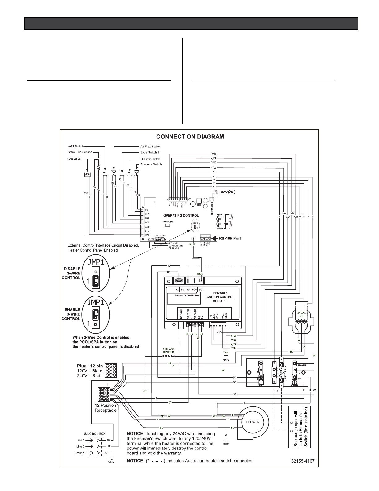
RS-485 Combo Conversion Instructions for USA and Australian heater models
The following instructions describe how to replace the PCBA, Membrane Pad, Ignition Control Module
(ICM) and Wiring Harness in a MasterTemp or Sta-Rite pool and spa heater (USA and Australia
models) that doesn’t have RS-485 communication capability.
Contents
RS-485 Combo Conversion Replacement (USA) page 2-5
RS-485 Combo Conversion Replacement (Australia) page 6-8
P/N 476251.A 9/2020
1
Page 2
RS-485 COMBO CONVERSION REPLACEMENT INSTRUCTIONS (USA)
476211 RS-485 COMBO CONVERSION (USA)
Parts List
P/N Description Qty.
466225 WH HRN US W/ FC 1
476221 ICM W/ FLAME SENSE US 1
476201 MEM PAD MT 6 BUTTONS 1
476199 PCBA MT/MET HTR W/RS485 1
476251 INSTALLATION INSTRUCTIONS 1
462049 RS-485 COMBO CONVERSION (AUSTRALIA)
Parts List
P/N Description Qty.
476226 WH HRN AUSTRALIA W/ FC 1
476222 ICM W/ FLAME SENSE AU 1
476251 INSTALLATION INSTRUCTIONS 1
476201 MEM PAD MT 6 BUTTONS 1
476199 PCBA MT/MET HTR W/RS485 1
2
Page 3
RS-485 COMBO CONVERSION REPLACEMENT INSTRUCTIONS (USA)
When installing this kit, basic safety precautions should always be followed. Read and follow all instructions.
Required installation tools:
• Powered socket/nut driver
• 1/4” nut driver bit
• 5/16” socket and nut driver
• 3/8” nut driver
CAUTION! Before starting: Always disconnect AC power to the heater before proceeding with
the wire harness replacement instructions.
CAUTION!: Before unplugging ICM connector plugs, be sure to match the
wire identication on both the existing and replacement wire harnesses.
To replace the membrane pad PCBA on a MasterTemp
®
Heater
To open the heater:
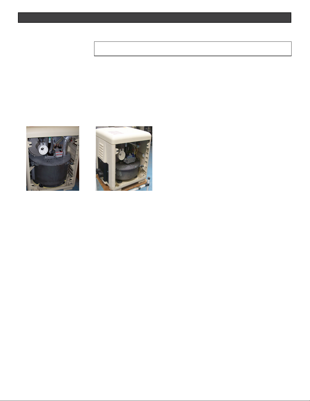
1. Remove left side panel from the heater (Fig. 1 and Fig. 2). Remove the four (4) wing nuts holding the top in place.
FIG. 1.
MasterTemp
2. Disconnect the wire harness from the back of the PCBA.
3. Disconnect the membrane pad from the PCBA.
4. Remove the four (4) screws holding the PCBA and remove the PCBA.
5. Peel the membrane pad from the top panel by pulling one of the corners. Set the panel aside.
6. Disconnect the wires from the ICM. Remove the two (2) screws that secure the ICM to the junction box.
7. Route the membrane pad connector through the top panel slot in order to connect it to the control board. Peel off the membrane
pad backing off the new membrane.
8. Align the membrane pad with the bottom of the recess in the lid and press firmly into place. Smooth the membrane pad with your
hand.
9. Place new PCBA into underside of cover and secure with four (4) mounting screws.
10. Reconnect the membrane pad to the PCBA (note the arrow on the membrane connector should be on the bottom)the upper jackets
halves from the heater (Fig. 3).
11. Place lid assembly aside and continue with replacing the ICM and Wire Harness.
STD Heater
FIG. 2.
MasterTemp 125 Heater
3
Page 4
RS-485 COMBO CONVERSION REPLACEMENT INSTRUCTIONS (USA)
F
I
L
T
E
R
PUMP
AUX
1
AUX
2
H
IG
H
SPE
ED
L
OW
S
PE
ED
BOOS
TE
R P
UM
P
Retaining
Pins
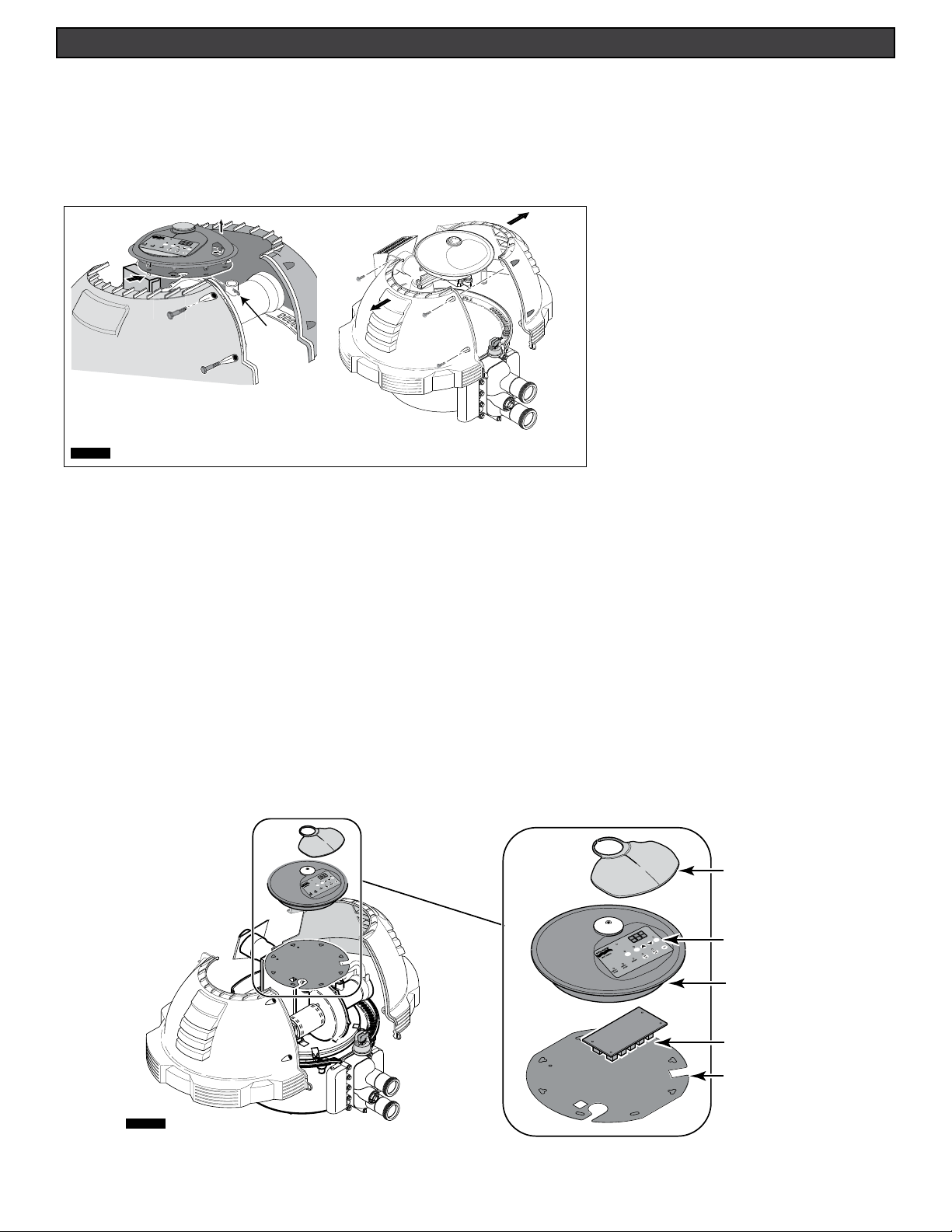
To replace the membrane pad and PCBA on a Sta-Rite Max-E-Therm
1. Unbolt the four bolts and separate the jackets halves. Pull hair pin clips. (Fig. 3).
2. Press the plastic clips on the control panel assembly.
3. Lift control panel assembly off of support plate.
4. Disconnect the connectors from the control panel assembly.
FIG. 3.
Max-E-Therm Heater
5. Disconnect the wire harness from the back of the PCBA.
6. Disconnect the membrane pad from the PCBA.
7. Remove the four (4) screws holding the PCBA and remove the PCBA
8. Peel the membrane pad from the top panel by pulling one of the corners.
9. Route the membrane pad connector through the top panel slot in order to connect it to the control board. Peel off the membrane
backing
10. Align the membrane pad with the bottom of the recess in the lid and press firmly into place. Smooth the membrane pad with your
hand.
11. Place new PCBA into underside of cover and secure with four (4) mounting screws.
12. Reconnect the membrane pad to the PCBA (note the arrow on the membrane connector should be on the bottom)the upper
jackets halves from the heater (Fig. 3).
13. Route the membrane pad connector through the top panel slot to connect to the control board. Peel of the membrane backing.
Align the membrane pad properly onto the area of the top panel.
14. Set the lid assembly aside and continue replacing the ICM and wire harness replacing it with the new Control Board with RS-485
communication. Note: The PCBA is not serviceable.
Control Panel
FIG. 3b
AUX
2
EED
SP
W
LO
PUMP
TER
OS
BO
D
UX
PEE
S
A
IGH
1
H
ER
LT
FI
P
PUM
Heater Display
Cover
AUX
2
D
SPEE
W
LO
P
M
PU
TER
BOOS
D
E
AUX
H SPE
G
1
HI
FILTER
ON
F
F
O
NT
VE
SS
E
PR
B
TA
T
LO
I
P
PUMP
Membrane Pad
(Included with Kit)
Control Board
Enclosure Kit
Control Board
Index Plate
FIG. 4.
4
Page 5
RS-485 COMBO CONVERSION REPLACEMENT INSTRUCTIONS (USA)
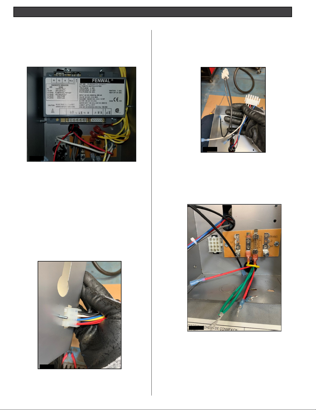
To replace the Ignition Control Module:
1. Disconnect all connector plugs and wires from the legacy
ICM. Remove the screws from the legacy ICM. Remove
ICM from the heater. (Fig. 5).
2. Install the new ICM into the heater Control Box compartment. Secure the unit with the two (2) screws.
FIG. 5.
To replace the wire harness:
- LEGACY WIRE HARNESS (USA) (P/N 42001-0104):
Disconnect all connector plugs and wires from all heater
components. Remove the wire harness from the heater.
- Install wire harness (USA) (P/N 476221):BEFORE
YOU START, LAY OUT THE WIRING HARNESS.
3. Bring the Flat 5-pin plug, 2-pin plug and multi-pin
connector into the control box. Install the bushing in the
hole. Also, bring the Flame current cable into the control
box. (Fig. 7).
FIG. 7.
4. Route the Red and Green wires into the Control Box
through the bottom hole. Plug the Fireman’s jumper into
the terminal board. Install bushing. Be sure the bushings
are install when routing the wires into the Junction box.
(Fig. 8). Note: The plugs are shown in the control box and
the Fireman’s jumper installed.
1. Cut one tie to release two jumpers.
2. Route the 12-pin plug in the control box from the back.
The plug is shown from outside the Control Box. (Fig. 6.)
Note: Narrow key hole in the upper right corner of the
plug.
FIG. 6.
FIG. 8.
5
Page 6

RS-485 COMBO CONVERSION REPLACEMENT INSTRUCTIONS (USA)
5. Connect BLACK and RED wires to terminal board
connections. Match wire identification with terminal
marking. (Fig. 9).
FIG. 9.
6. From outside the Control Box, push the clip through its
hole in the back of the box. (Fig. 10).
8. Connect the 2-pin connector to F1 / F2 at the upper
right side of the ICM. (Fig. 12)
FIG. 12.
9. Connect 5-pin connector to lower right side of the
ICM and connect multi-pin connector next to 5-pin
connector. (Fig. 13).
FIG. 10.
7. Install the bushing in the top of the control box. Use
(Fig. 11)
FIG. 13.
10. Mount the bundle of wires on the blower. Plug in the
blower motor. (Fig. 14).
FIG. 14.
FIG. 11.
6
Page 7

RS-485 COMBO CONVERSION REPLACEMENT INSTRUCTIONS (USA)
11. Connect the Stack Flu sensor. (Fig. 15)
FIG. 15.
12. Connect the Gas Valve. (Fig. 16)
14. Connect the Blower assembly. (Fig. 18).
FIG. 18.
15. Plug in the Transformer. (Fig. 19).
FIG. 16.
13. Connect the Air Flow Switch. (Fig. 17).
FIG. 17.
FIG. 19.
16. Route wires (HL, AGS, WP, etc) to the manifold. (Fig. 20).
FIG. 20.
7
Page 8

RS-485 COMBO CONVERSION REPLACEMENT INSTRUCTIONS (USA)
17. Connect the Thermistor sensor and High Limit Switch.
Note: The Thermistor sensor is located at the top of the
manifold. The High Limit switch is located at the bottom of
the manifold. (Fig. 21).
FIG. 21
18. Connect the Water Pressure Switch and AGS switch.
The AGS is located on the right side. (Fig. 22).
20. Connect one end of the flame cable (Red/Black wires)
to Control Board and the other end to the upper left
side of the ICM. (Fig 24)
FIG. 24.
21. Reassemble the heater control panel assembly. Be sure
that the control panel can be adjusted without having to
lean over the exhaust vent.
22. Replace hair pin clips. See Fig. 2, 3) page 3.
23. Replace jacket halves and bolts and tighten.
FIG. 22.
19. Plug the harness into the back of the circuit board.
(Fig. 23).
FIG. 23.
8
Page 9

RS-485 COMBO CONVERSION REPLACEMENT INSTRUCTIONS (AUSTRALIA)
When installing this kit, basic safety precautions should always be followed. Read and follow all instructions.
Required installation tools:
• Powered socket/nut driver
• 1/4” nut driver bit
• 5/16” socket and nut driver
• 3/8” nut driver
CAUTION! Before starting: Always disconnect AC power to the heater before proceeding with
the wire harness replacement instructions.
CAUTION!: Before unplugging ICM connector plugs, be sure to match the
wire identication on both the existing and replacement wire harnesses.
To replace the membrane pad PCBA on a MasterTemp
1. MasterTemp Heater: Remove left side panel from the heater (Fig. 1
and Fig. 2).
FIG. 1.
MasterTemp
2. Disconnect the wire harness from the back of the PCBA.
3. Disconnect the membrane pad from the PCBA.
4. Remove the four (4) screws holding the PCBA and remove the PCBA.
5. Peel the membrane pad from the top panel by pulling one of the corners. Set the panel aside.
6. Disconnect the wires from the ICM. Remove the two (2) screws that secure the ICM to the junction box.
7. Route the membrane pad connector through the top panel slot in order to connect it to the control board. Peel off the membrane
pad backing
8. Align the membrane pad with the bottom of the recess in the lid and press firmly into place. Smooth the membrane pad with your
hand.
9. Place new PCBA into underside of cover and secure with four (4) mounting screws.
10. Reconnect the membrane pad to the PCBA (note the arrow on the membrane connector should be on the bottom)the upper jackets
halves from the heater (Fig. 3).
11. Place lid assembly aside and continue with replacing the ICM and Wire Harness.
STD Heater
FIG. 2.
MasterTemp 125 Heater
®
Heater
9
Page 10

RS-485 COMBO CONVERSION REPLACEMENT INSTRUCTIONS (AUSTRALIA)
F
I
L
T
E
R
PUMP
AUX
1
AUX
2
H
IG
H
SPE
ED
L
OW
S
PE
ED
BOOS
TE
R P
UM
P
Retaining
Pins
To replace the membrane pad and PCBA on a Sta-Rite Max-E-Therm
1. Unbolt the four bolts and separate the jackets halves. Pull hair pin clips. (Fig. 3).
2. Press the plastic clips on the control panel assembly.
3. Lift control panel assembly off of support plate.
4. Disconnect the connectors from the control panel assembly.
FIG. 3.
Max-E-Therm Heater
5. Disconnect the wire harness from the back of the PCBA.
6. Disconnect the membrane pad from the PCBA.
7. Remove the four (4) screws holding the PCBA and remove the PCBA
8. Peel the membrane pad from the top panel by pulling one of the corners.
9. Route the membrane pad connector through the top panel slot in order to connect it to the control board. Peel off the membrane
backing
10. Align the membrane pad with the bottom of the recess in the lid and press firmly into place. Smooth the membrane pad with your
hand.
11. Place new PCBA into underside of cover and secure with four (4) mounting screws.
12. Reconnect the membrane pad to the PCBA (note the arrow on the membrane connector should be on the bottom)the upper
jackets halves from the heater (Fig. 3).
13. Route the membrane pad connector through the top panel slot to connect to the control board. Peel of the membrane backing.
Align the membrane pad properly onto the area of the top panel.
14. Set the lid assembly aside and continue replacing the ICM and wire harness replacing it with the new Control Board with RS-485
communication. Note: The PCBA is not serviceable.
Control Panel
FIG. 3b
AUX
2
EED
SP
W
LO
PUMP
TER
OS
BO
D
UX
PEE
S
A
IGH
1
H
ER
LT
FI
P
PUM
Heater Display
Cover
AUX
2
D
SPEE
W
LO
P
M
PU
TER
BOOS
D
E
AUX
H SPE
G
1
HI
FILTER
ON
F
F
O
NT
VE
SS
E
PR
B
TA
T
LO
I
P
PUMP
Membrane Pad
(Included with Kit)
Control Board
Enclosure Kit
Control Board
Index Plate
FIG. 4.
10
Page 11

RS-485 COMBO CONVERSION REPLACEMENT INSTRUCTIONS (AUSTRALIA)
To replace the wire harness on a MasterTemp® or Max-E-Therm® Heater:
To replace the Ignition Control Module:
1. Disconnect all connector plugs and wires from the legacy
ICM. Remove the screws from the legacy ICM. Remove
ICM from the heater. (Fig 5.)
2. Install the ICM onto the heater junction box compartment.
Secure the unit with the two (2) screws.
3. Reconnect the membrane pad to the PCBA. Note the
arrow on the membrane connector should be on the
bottom.
2. Place the 12-pin plug in the control box from the back.
The plug is shown from the inside the control box. Note:
narrow key in upper right corner of plug. (Fig. 6.)
FIG. 6.
3. Bring the Flat 5-pin plug, 2 -pin plug into the control box.
Install the bushing. If heater has new Control Board bring
flame current cable as well.
(Fig. 7.)
FIG. 5.
To replace the wire harness:
- LEGACY WIRE HARNESS (USA) (P/N 474163): Discon-
nect all connector plugs and wires from all heater components. Remove the wire harness from the heater.
- Install wire harness (USA) (P/N 476222):BEFORE YOU
START, LAY OUT THE WIRING HARNESS.
1. Cut one tie to release two jumpers.
FIG. 7.
11
Page 12

RS-485 COMBO CONVERSION REPLACEMENT INSTRUCTIONS (AUSTRALIA)
4. Route the Red and Green wires into the Control Box
through the bottom hole. Plug the Fireman’s jumper into
the terminal board. Install bushing. Be sure the bushings
are install when routing the wires into the Junction box.
(Fig. 8). Note: The plugs are shown in the control box and
the Fireman’s jumper installed.
FIG. 8.
7. From outside the Control Box, push the clip through its
hole in the back of the box. (Fig. 11).
FIG. 11.
5. Install the bushing in the top of the control box. (Fig. 9)
FIG. 9.
6. Connect wires to terminal board connections. Match wire
identification with terminal marking. (Fig. 10)
8. Connect the 2-pin connector to F1 / F2 at the upper
right side of the ICM. (Fig. 12)
FIG. 12.
9. Connect 5-pin connector to lower left side of the ICM.
(Fig. 13).
FIG. 10.
FIG. 13.
12
Page 13

RS-485 COMBO CONVERSION REPLACEMENT INSTRUCTIONS (AUSTRALIA)
10. Connect S1/240, located on the left side of the 5-pin
connector. (Fig. 14).
FIG. 14.
11. Plug in the transformer. (Fig. 15).
14. Connect the Orange/Yellow wire to IND ¼” tab at ICM.
(Fig. 18)
FIG. 18.
15. Connect the Red/yellow wire to VAL ¼” tab at the ICM,
(Fig. 19)
FIG. 15.
12. Connect the Air Flow sensor. (Fig. 16).
FIG. 16.
13. Connect the Blue/Yellow wire to TH ¼” tab at ICM.
(Fig. 17)
FIG. 19.
16. Connect the White/Yellow wire to GND ¼” tab at the ICM.
(Fig. 20)
FIG. 17.
FIG. 20.
13
Page 14

RS-485 COMBO CONVERSION REPLACEMENT INSTRUCTIONS (AUSTRALIA)
17. Connect the 24 VAC plug at the upper right side as
shown in Fig. 21.
FIG. 21.
18. Connect the Blower assembly.(Fig. 22).
20. Connect the Thermistor sensor and High Limit Switch. Note:
The Thermistor sensor is located at the top of the manifold.
The High Limit switch is located at the bottom of the manifold.
(Fig. 24).
FIG. 24.
21. Connect the Flu Sensor. (Fig. 25).
FIG. 22.
19. Route wires (HL, AGS, WP, etc) to the manifold. (Fig. 23).
FIG. 23.
FIG. 25.
22. Connect the Gas Valve. (Fig. 26).
FIG. 26.
14
Page 15

RS-485 COMBO CONVERSION REPLACEMENT INSTRUCTIONS (AUSTRALIA)
23. Connect the cables that supply power to the heater. (Fig. 27).
FIG. 27.
24. Connect the Water Pressure Switch and AGS switch.
The AGS is located on the right side. (Fig. 28).
26. Connect one end of the flame cable (Red/Black wires
to Control Board and the other end to the upper left
side of the ICM. (Fig 30).
FIG. 30.
27. Reassemble the heater control panel assembly. Be sure
that the control panel can be adjusted without having to
lean over the exhaust vent.
28. Replace hair pin clips. See Fig. 2, 3) page 3.
29. Replace jacket halves and bolts and tighten.
FIG. 28.
25. Plug the harness into the back of the circuit board.
(Fig. 29).
FIG. 29.
15
Page 16

1620 HAWKINS AVE., SANFORD, NC 27330 • (919) 566-8000
10951 WEST LOS ANGELES AVE., MOORPARK, CA 93021 • (805) 553-5000
Technical Support: 800.831.7133
www.pentair.com
All indicated Pentair trademarks and logos are property of Pentair Inc. or its global aliates in the U.S.A. and/or other countries. Third
party registered and unregistered trademarks and logos are the property of their respective owners
© 2020 Pentair. All rights reserved. This document is subject to change without notice.
* 476251*
P/N 476251.A 9/2020
 Loading...