

Pentair ONGA INTELLIMASTER INJ-4500L 075, ONGA INTELLIMASTER INJ-4500L 022, ONGA INTELLIMASTER INJ-4500L 015 User Quick Manual
Page 1
USER QUICK MANUAL
ONGA
R
Page 2

SAFETY INSTRUCTIONS
Please read the IMPORTANT SAFETY INFORMATION below, and all Warning and
Caution information elsewhere.
Intellimaster series is intended for professional incorporation into complete equipment or systems as part of a fixed
installation. If installed incorrectly it may present a safety hazard. The Intellimaster series uses high voltages and
currents, carries a high level of stored electrical energy, and is used to control mechanical plant that may cause injury.
Close attention is required to system design and electrical installation to avoid hazards in either normal operation or in
the event of equipment malfunction. Only qualified electricians are allowed to install and maintain this product.
System design, installation, commissioning and maintenance must be carried out only by personnel who have the
necessary training and experience. They must carefully read this safety information and the instructions in this Guide
and follow all information regarding transport, storage, installation and use of the Intellimaster series, including the
specified environmental limitations.
Electric shock hazard! Disconnect and ISOLATE the Intellimaster series before attempting any work on it. High
voltages are present at the terminals and within the drive for up to 10 minutes after disconnection of the electrical
supply. Always ensure by using a suitable multimeter that no voltage is present on any drive power terminals prior to
commencing any work.
Where supply to the drive is through a plug and socket connector, do not disconnect until 10 minutes have elapsed
after turning off the supply.
The STOP function does not remove potentially lethal high voltages. ISOLATE the drive and wait 10 minutes before
starting any work on it. Never carry out any work on the Drive, Motor or Motor cable whilst the input power is still applied.
The entry of conductive or flammable foreign bodies should be prevented. Flammable material should not be placed
close to the drive Relative humidity must be less than 95% (non-condensing).
Ensure that the supply voltage, frequency and single phase input correspond to the rating of the Intellimaster as delivered.
Never connect the mains power supply to the Output terminals U, V, W.
Do not install any type of automatic switchgear between the drive and the motor.
The driven motor can start at power up if the enable input signal is present.
Do not perform any flash test or voltage withstand test on the Intellimaster series. Any electrical measurements
required should be carried out with the Intellimaster series disconnected.
Danger : Indicates a risk of electric shock, which,
if not avoided, could result in damage to the
equipment and possible injury or death.
Danger : Indicates a potentially hazardous
situation other than electrical, which if not
avoided, could result in damage to property.
Page 3
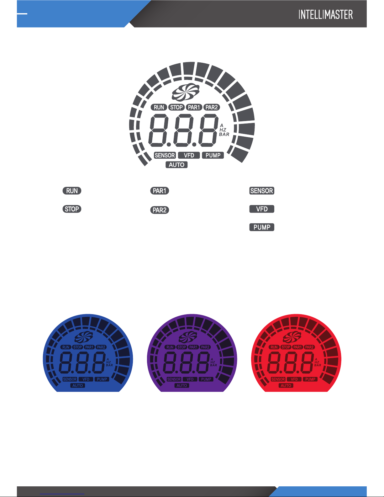
DISPLAY
2> LCD Color
1> LCD Display
<Alarm is Red><Stop is Purple><Operation is Blue>
Sensor Alarm
VFD Alarm
Pump Alarm
Parameter 1
Parameter 2
VFD Operation
VFD Stop
Page 4
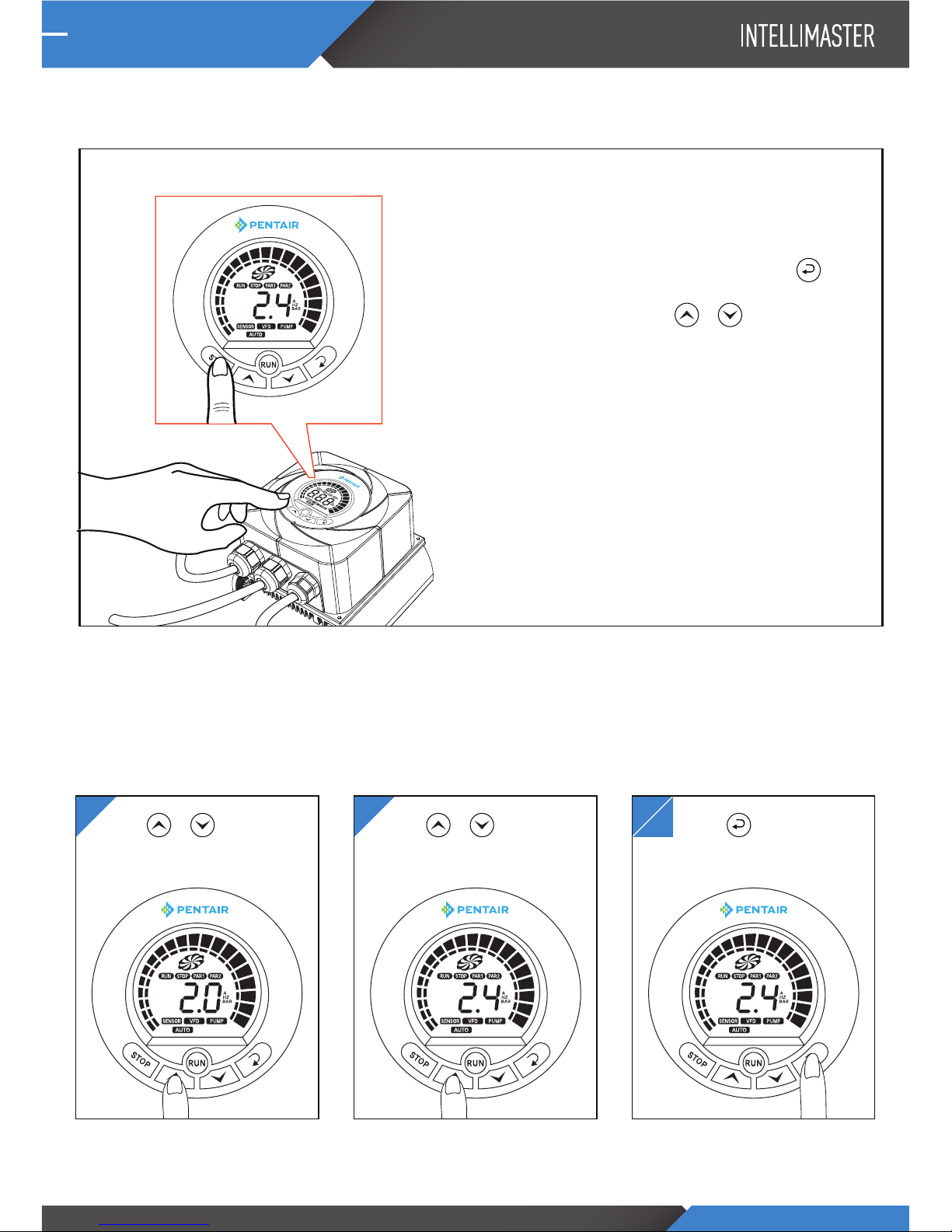
Changing to Constant Speed(MANUAL OPERATION MODE)
• To set to MANUAL OPERATION MODE, press down on
the STOP button for 3 seconds. The AUTO indication will
disappear. In MANUAL OPERATION MODE, press the
and once the indication is on Hz, change the constant speed
required by pressing either the or and press the
run button once the Hz is selected.
Changing to Constant Pressure(AUTO OPERATION MODE)
• To set to AUTO OPERATION MODE, press down on the
STOP button for 3 seconds. The AUTO indication will
appear. In AUTO OPERATION MODE, the pump will operate
according to the set pressure.
*NOTE: THIS IS THE CURRENT DEFAULT SETTING
21
SETTING
1> Switching to Constant Pressure or Constant Speed
2> Setting the pressure
Press or
button for 2 seconds.
Press or
button to set the desired pressure.
3
4
Press button to
complete the pressure setting.
STOP
RUN
Page 5

SETTING PARAMETER
1> Parameter1
Inverter Parameter
2> Parameter2
Booster Parameter
First, stop the inverter, then press the and button stimultaneously.
First, stop the inverter, then press the and button stimultaneously.
50
50
240
25
120
1.5
15
3
3
1
2
150
10
120
60
8
428
5.0 ~ 70.0 Hz
5.0 ~ 70.0 Hz
50 ~ 240 VAC
5.0 ~ 70.0 Hz
3 ~ 220 VAC
0.1 ~ 20.0 Hz
3 ~ 100 VAC
3.0 ~ 99.9 Sec
3.0 ~ 99.9 Sec
0 : Deceleration to stop
1 : Coast to stop
0 : 1 HP (3.1A)
1 : 1.5 HP (4.3A)
50 ~ 200 %
2.0 ~ 99.9 Sec
100 ~ 200 %
50 ~ 90 %
3.0 ~ 15.0 Hz
444 - Reset setting
422 - Reset for 220VAC
424 – Reset for 240VAC
Max Frequency
Max Voltage Frequency
Max Voltage
Mid-Point Frequency
Mid-Point Voltage
Min Frequency
Min Voltage
ACC Time
DEC Time
Stop Mode
Pump HP
Overload Rate
Overload Time
Over-Voltage application Rate
Low-Voltage application Rate
Carrier Frequency
TEST
Version information
P 00
P 01
P 02
P 03
P 04
P 05
P 06
P 07
P 08
P 09
P 10
P 11
P 12
P 13
P 14
P 15
P 16
0.3 ~ 6.0 Bar
-3.0 ~ -0.2 Bar
1.0 ~ 16.0 Bar
-9.9 ~ 9.9 Bar
0.2 ~ 2.0 Bar
0 : Not use
1 ~ 999 Sec
0.5 ~ 5.0 A
0 : Not use
1 ~ 999 Sec
0 : CW 1 : CCW
1 ~ 200
1 ~ 200
1 ~ 200
0 ~ 20 ( OC,OL,OV,LV inverter err only)
0:Stop, 1:Run, 2:Last Key state
1, XX
Set Press
Run deviation
Sensor type
Sensor Adjust
Low press
Stop Time of
Low press
Low Current
Stop Time of
Low Current
Pump Direction
P
I
D
Auto Reset
The initial operation status
3.5
-0.5
16
0
0.5
20
3.3
10
0
25
40
40
5
2
-
-
-
Version information
B 00
B 01
B 02
B 03
B 04
B 05
B 06
B 07
B 08
B 09
B 10
B 11
B 12
B 13
B 14
B 15
B 16
B 17
P 17
Display Description Value Default (240V)
Display Description Value Default (240V)
Page 6

SPECIFICATION
Model Number 075 015 022
Insulation Class IP55
2Phase(2line)220/240V(±10%), 50/60Hz(±5%)
3Phase220/240V
PWM Type
0~120Hz
V/F Control (Regular Torque, Low Deceleration Torque)
150% of rated current for 1 minute
0.1~60 seconds (Independent settings for Accel/Decel Time)
0.1-25kg/cm
2
RESS-SEN (4-20mA Pressure Transmitter) , 1-5V voltage type(option)
Over-Current, Over Voltage, Under Voltage, Overheating, Overload, Low Pressure,
High Pressure, Water Low Level
PID Control, Auto Restart, Alarm Auto Reset, RS-485 Communication
Max. Applicable
Motor Output
KW
HP
0.75 1.1
1 2
3
2.2
3
5 7 10
Max linkage inverter
Rated Input AC Voltage
Rated Output Voltage (V)
Rated Output Current (A)
Control System
Output Frequency Range
Torque Characteristics
Overload Endurance
Accel/Decel Time
Pressure sensor Range
Analog Input Signal
Protections
Other Functions
Heat Sink
2.5kg
Cooling Methods
Weight (kg)
INJ-4500L
Page 7

ALARM LOG & CONFIRMATION
Alarm Log (Max 20 logs)
In Main display, Press the
and
button longer and together.
Over current
Low voltage
Over voltage
Over load
Fail
communication
Error of sensor
Stop for
low current
Low Pressure
Over-current on the inverter/
Abnormal operation of the motor/
Short of the motor’s output line
Low-voltage on the inverter
Over-voltage on the inverter,
when excessive voltage is
inputted to the inverter
Overload on the inverter/
Abnormal operation of the
motor/pump
Master and slave are
communication fail
Sensor fail to connect
When the water level
of the tank is low/
When air enters the pumps
When the pressure drops
below the set “Low press’
If problem repeats/
Check the pump/motor
Check the input voltage
Check the input voltage
Check the pump/motor
Check communication line
Check the connection
of the sensor/
Change the sensor
Check the tank/
Remove air from the pump
Lower the “Low press”/
Adjust the setting
for pump operation
AlarmDisplay Reason Countermeasures
Page 8

NOTES
Page 9

NOTES
Page 10

NOTES
Page 11

NOTES
Page 12

 Loading...