

NRG-Temp
THERMAL MANAGEMENT SOLUTIONS
ML-NRGTemp-IM-INST314 R3


English:
Deutsch:
Français:
Nederlands:
Norsk:
Svenska:
Dansk:
Suomi:
Polski:
Русский:
Română
Digital Timer Thermostat 6
Operation and user manual
Digitaler Thermostat mit Zeitschaltuhr
Installation und Betrieb
Thermostat à horloge numérique 79
Guide d’installation et d’utilisation
Thermostaat met digitale timer 115
Operation and user manual
Termostat med digitaltimer 152
Installasjon og anvendelse
Digital timertermostat 187
Installation och användning
Digital timertermostat 223
Installation og betjening
Digitaalinen ajastintermostaatti 259
lattialämmitykselle
Operation and user manual
Termostat z timerem cyfrowym 294
Instrukcja montażu i obsługi termostatu
Цифровое термореле с таймером 330
Инструкция по монтажу и эксплуатации
Cronotermostat digital 370
Manual de utilizare
41
For instructions in other languages,
go to : www.pentairthermal.com

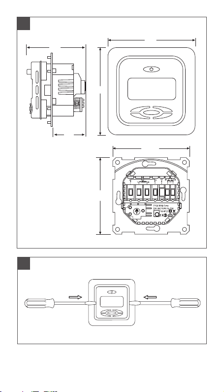
1
57
82
33
70.5
82
70.5
2
5

ENGLISH
1
2
3
4
5
6
Technical specification 8
Description 9
Mounting and installation 10
Program selection 13
Operation Comfort Mode (Co) 17
5.1 Getting started 17
5.2 Optional functions 19
5.2.1 Heat Booster 19
5.2.2 External set back) 19
5.2.3 Lock function) 20
5.3 Optional functions 20
5.3.1 Menu 1: Temperature viewing 20
5.3.2 Menu 2: Temperature calibration 20
5.3.3 Menu 3: Delayed start-up 20
5.3.4 Menu 4:
Display backlight duration
23
5.3.5 Menu 5: "First warming" function 23
5.3.6 Menu 6: Heating running time 23
5.3.7 Menu 7: Adjustable switching
hysteresis 25
Operation EcoHome
or EcoOffice Mode 25
6.1 Getting started 25
6.2 Optional functions 29
6.2.1 Boost function 29
6.2.2 Lock function 29
6.2.3 Configuration menu 29
6

6.3 Installer's menu 30
Menu 1: Sensor mode 30
Menu 2: Service read out 31
Menu 3: Calibration of the
temperature set value 31
Menu 4: Display backlight on duration 33
Menu 5-6: Min-max setting
for room sensor
6
Menu 7-8: Min-max setting
for floor sensor
Menu 9: Adaptive function ON/OFF 35
Menu A: "First warming" function
Menu B: Running time 35
Menu C: Adjustable switching
hysteresis 35
Operation in Standby mode 35
7
Trouble shooting 36
8.1 Error Codes 36
8
8.2 Monitoring of the temperature
sensor 36
Factory settings 37
9
33
34
35
7

1. TECHNICAL SPECIFICATIONS
Supply voltage 230VAC, +10%,
Power consumption, average 4 VA
Main power switch 2-pole
Relay output - heating cable 230V, max. 13A
Ambient temperature – operation 0 +40°C
Ambient temperature – transport –20 +50°C
Temperature range, floor sensor +5 +35°C
Temperature range, room
sensor
Accuracy – floor/room sensor ± 0,5°C
Switching hysteresis 0,5°C (Factory settings
Control modes Floor sensor
Economy programs
EcoHome; EcoOffice
Back-up for set values In non-volatile memory
Back-up for time and date 24 hours
Optional external control Set back function
Protection class IP 21
Terminals Max. 2,5 mm
Floor sensor with 3 m cable NTC, 10K / 25°C.
Maximum length of floor sensor
cable
Dimension with frame (Fig.1) H 82 x W 82 x D 57 mm
Colour Polar white RAL 9010
Approvals Semko, VDE, eu.bac, CE
8
–15%, 50/60 Hz
+5 +40°C
adjustable between
0,2-2.0°C)
Room sensor
Room sensor with floor
sensor as a limiter
(Not in Comfort mode
2 preset-programs;
editable in time blocks of
30 min
–3.5°C (Not in programs
EcoHome and EcoOffice)
2
100 m, 2 x 1,5 mm
2
(230VAC cable type)
)

2. DESCRIPTION
NRG-Temp is a smart thermostat for underfloor
heating.
NRG-Temp provides the following features and
functions:
• Heating system control by means of an external
floor sensor or integrated room sensor.
• Load capacity of the output relay, 13A/230V
(3000W)
• 2-pole main power switch
• Display with blue backlight
• System "Boost" function
The set temperature can be increased for 2
hours reverting automatically to the original
temperature setting.
• Keypad lock function.
• Fail safe mode in the event of a system error/
fault.
• Enclosure protection class IP21
• Floor sensor cable. Length - 3 metres.
• "First warming" function for gradual warming of
new screed.
• Summer mode (Heating Off)
• External set back in Comfort mode
Extra terminal which can be used as an
external closing contact to reduce the set
temperature by 3,5°C
• Delayed Start-Up in Comfort mode
• Economy programs (EcoHome, EcoOffice)
2 different standard efficiency programs for
specific room types which can be edited manually
• Adaptive function (EcoHome, EcoOffice)
The adaptive function automatically changes the
start time of the heating system so the desired
temperature is reached at the required time.
9

• The thermostat is supplied with an assembly
frame and a front plate for the ELJO Trend / B&J
Jussi / Merten (Plan, Smart, Arc, Atelier, M1,
Antik, Termo, M-Star) / Jung (AS) / Gira (ST55
Standard, E2) wall box system. An extra front
plate for the square sized frames such as ELKO
RS is also included
• Approved by SEMKO, VDE, eu.bac, CE
3. MOUNTING AND INSTALLATION
Thermostat
NRG-Temp is intended for flush mounting in a
standard 65 mm wallbox. It should be positioned
approximately 1.5 metres above the floor, protected
from direct sunlight and draughts. All electrical
conduits passing into the thermostat box that contain
cables must also be sealed to protect the thermostat
against draughts, e.g. with a piece of insulation in
the conduit outlet.
NRG-Temp can also be mounted in an external wall
box. If the thermostat will be mounted on a rough
wall surface, e.g. bricks, use silicon glue to make a
seal with the top frame. Assembly frame and front of
thermostat can be removed by pushing with a screw
driver on the two fasteners located on the sides of
the thermostat. (Fig. 2)
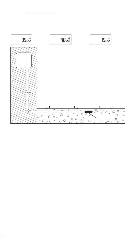
Floor sensor
The floor sensor should be installed in a separate
flexible conduit/hose for easy replacement. For best
control performance, position the floor sensor between
two heating cables as close as possible to the top floor
surface. Do not position the floor sensor tip closer than
3 cm to the heating cable.
The floor sensor cable can be extended to 100 m with
a separate standard installation cable 2 x 1.5 mm
(230VAC).
In order to avoid signal disturbance resulting in a
possible malfunctioning of the thermostat, the sensor
should not be installed in a conduit together with other
cables.
10
2

Connection of the thermostat
The thermostat must be connected to 230VAC
according to the circuit diagrams. When using
multiple heating cables, totalling over 13A, a
contactor with integrated suppression device must
be used. If the protective earth terminal, PE, on the
thermostat is used, the incoming power cable to the
heating cable should be connected to the common
earth terminal on the thermostat, otherwise a
separate terminal connection block (not included )
must be used.
Product specific information for use with
floorheating systems
• Use with T2QuickNet:
T2QuickNet is approved with the thermostat
working in floor sensor mode. Be aware that the
floor sensor must be installed and activated for
an installation with T2QuickNet.
• Use with T2Red (T2Reflecta) self-regulating
systems:
Self-regulating heating cables have an inrush
current at start up. In order to guarantee the life
time of the thermostat, the maximum load of the
self-regulating application in nominal conditions
is limited to 10A.
A 13A self-regulating load will reduce the life
time of the relay contacts.
11
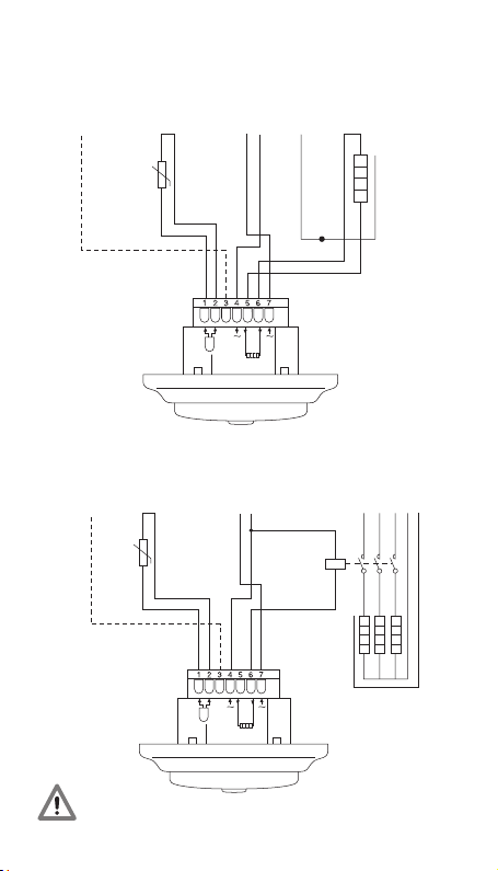
Direct, connection – e.g. single heating circuit
L
N
L
L
Heating cable
PE
PE
230 VAC
Max.13A
L
PE
N
Pilot wire
signal
(France)
Floor
sensor
NTC
10K
Power supply
230 VAC
L
FP
N
N
SENSOR
HEAT
N
Connection via contactor – e.g. 3 heating circuits
Pilot wire
signal
(France)
Floor
sensor
NTC
10K
Power supply
230 VAC
Power supply to
heating cables
L1 L2 L3 N PE
1 3 5
K1
A2
A1
2 4 6
L L L
PE
N N N
FP
N
L
N
L
SENSOR
HEAT
Do not use contactor without interference filter.
12
K1: contacter
with integrated
suppression
device

4. PROGRAM SELECTION
Thermostat controls
A
F
E
A: main power switch
B: OK/confirm button
C: “–“ decrease
D: “+” increase
E: “>” move right
F: “<” move left
C
D
B
First start – set the thermostat in operation:
Push in the main < > power switch, located on
the upper part of the thermostat.
The display lights, and the Comfort mode symbol
begins to flash to select the desired program mode.
13
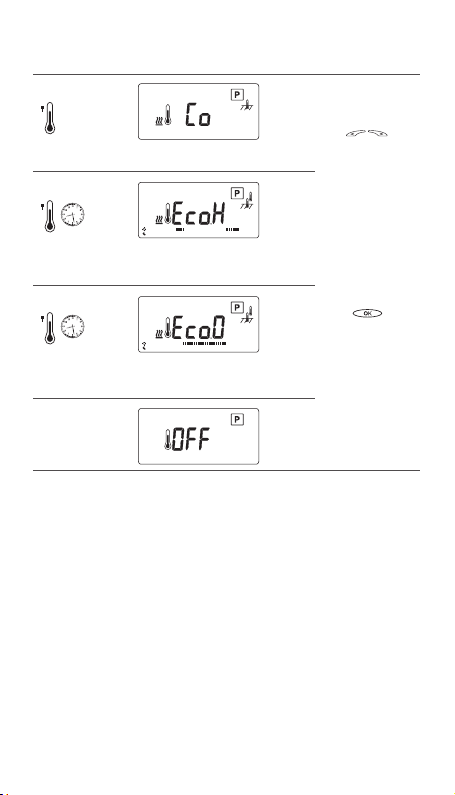
Program
selection
Comfort
temperature
adjustment
EcoHome
temperature
and time/date
adjustment
EcoOffice
temperature
and time/date
adjustment
Standby
•
0h • 3
•
0h • 3
Display
• • 6 • • 9 • •
• • 6 • • 9 • •
See
page
23
• •
• •
• •
• •
12
15
18
21
24
23
• •
• •
• •
• •
12
15
18
21
24
33
15
Program
selection
Scroll through
differrent
programs with
<
buttons
Press
<
button to
confirm
selected
program
>
>
14
•
0h • 3
• • 6 • • 9 • •
1
I
I
7
• •
• •
• •
12
15
• •
18
21
24
Function Symbols Comfort
Set time and date
Select program Comfort
Booster
(+5°C for 2 hours)
• Set desired
comfort
temperature
• Continuous
operation in
comfort mode
(override automatic program)
Select “Auto” to
run selected user
program.
• Set reduced
(Set-back)
temperature
or is shown
at external
program
• Continuous
operation in
reduced mode
(override automatic program)
–
= Co
✔ ✔
–
–
–
EcoHome
EcoOffice
✔ ✔
EcoHome:
EcoH
EcoOffice:
EcoO
✔
✔
✔
Standby
Standby:
OFF
–
–
–
–
15
•
0h • 3
• • 6 • • 9 • •
1
I
I
7
• •
• •
• •
12
15
• •
18
21
24
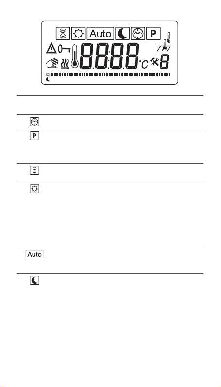
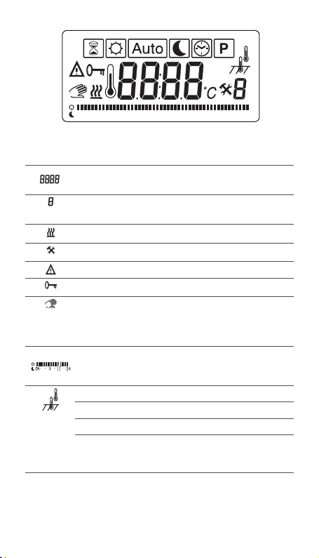
Read-out Symbols
Time, temperature
or error code
Day or menu
number
Heating cable on
Calibration mode
Error
Keypad locked
Temporarily
override the
Comfort
✔ ✔
✔ ✔
✔ ✔
✔ ✔
✔ ✔
✔ ✔
–
EcoHome
EcoOffice
✔
tempe-rature in
Auto mode
Graphical
indication of
–
✔
selected program
Sensor mode
i. Floor sensor
ii. Room sensor
iii. Room sensor
with floor tempe-
✔ ✔ ✔
✔ ✔ ✔
–
✔
rature limiter
Note: The function being set is indicated by a square
symbol around the function symbol. Example: If the
square is shown around the clock symbol, the time and
date function may be amended.
16
Standby
–
–
–
–
–
–
–
–
–

5. OPERATION COMFORT MODE [ ]
5.1 Getting started
Note: the square moves over the different symbols
when programming. The symbol in the square
indicates the active function: manual mode, automatic
mode by external signal, booster function.
The display illuminates and shows all features. Then it
shows the setting temperature and sensor mode. The
sensor mode is initialised automatically. If the floor
sensor cable is connected, it operates in floor sensor
mode. If the floor sensor cable is not connected, it
operates in room sensor mode.
After 5 sec. the thermostat checks if an external
control signal is connected.
If yes, the thermostat will be controlled according to the
set temperature and external signal. The symbol AUTO
is activated. If not, the thermostat will be controlled
according to the set temperature.
Adjust the set temperature, desired floor temperature
or room temperature, with the <
This is an approximate set value to get a comfort
temperature on the floor or in the room.
Heating-on symbol <
the heating cable is on.
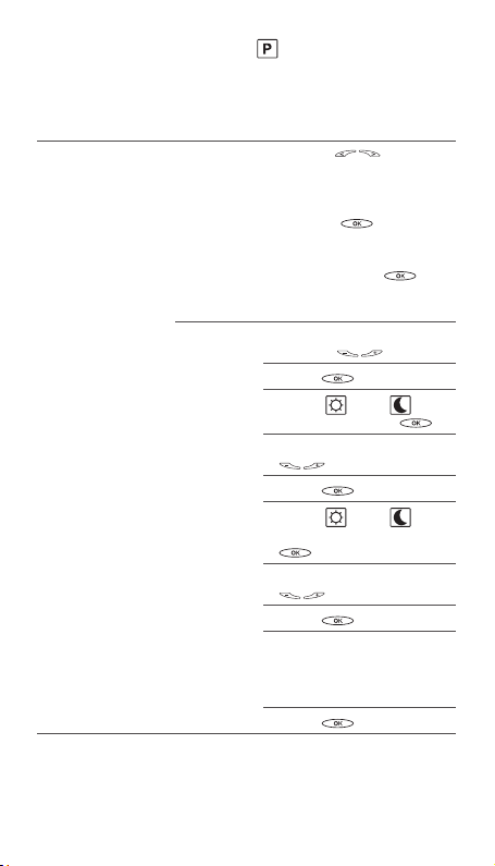
Choose another program
• Use the <
menu and activate P.
• The display switches to this view: ; P is
flashing.
• Confirm by pushing OK button to go in program
selection; Co is flashing.
• Select program EcoHome, EcoOffice or Standby
mode by
• using <
>.
<
> indicates on the display when
> buttons to scroll through the
> buttons and confirm by pressing
> buttons.
17
Learning Function
This function starts only if the thermostat has no floor
sensor connected, (‘Er3’ indicated briefly at start-up) only
in ambient sensing mode configuration.
At the first thermostat power-up (or after a factory
reset), the thermostat begins its own regulation
parameter calibration.
During this learning time, the user doesn’t have
access to ambient temperature:
Instead of temperature, a count down timer
from 2.1 hours to 0.1 hour
(0.1 hour = 6 minutes) is displayed.
The learning time is divided into two steps:
1. Time < 30min (0.5 hour) [ from 2.1h to 1.6h]:
the first half hour, the user is allowed to change
the set temperature and activate the floor warming
system. This period can be used by the installer to
check the floor warming system installation.
The set temperature can be adjusted by using
<
2. 30min < Time < 2hours [from1.6h to 0.1h]:
The thermostat doesn’t take into account the set
temperature. But during this period, the thermostat
can power on and off the floor warming system to
adjust its regulation parameters.
If there is a main power supply loss during this learning
period (main switch off or power supply failure), the
thermostat will restart the learning function.
At the end of this learning function, the thermostat is
automatically calibrated (adapted to the load linked
to the thermostat):
> keys.
18

This function will run at every factory reset of the
thermostat, if no floor sensor is attached.
5.2. Optional functions
5.2.1 Activating Heat booster <
This function is used for temporary increase of the
floor/room temperature by 5°C.
Push the confirmation button <
current set temperature will increase by 5°C for 2
hours and this increased temperature is shown on
the display. This automatically reverts to the set
temperature after 2 hours or if the confirmation
button is pushed again for 3 sec. within the 2 hour
period.
If external control is connected:
confirmation button <
thermostat will now be in Manual mode. Push again
the confirmation button <
for 3 sec. The thermostat will go in “booster” mode
and the current set temperature will increase by 5°C
for 2 hours. This increased temperature is shown on
the display. Automatic reverts to the set temperature
after 2 hours or if the confirmation button <
pushed again for 3 sec. within the 2 hour period.
> for 3 sec. The
>
> for 3 sec. The
Push the
>
5.2.2 External set back
To utilise the set-back function and reduce the
current set point by 3.5°C: Connect a closing contact
between the FP terminal and phase terminal e.g.
a closing timer switch. When the contact is closed,
the symbol "P" is displayed in the lower right corner,
indicating activation.
To enable manual control mode: Push the
confirmation button for 3 seconds. Normal set
temperature control is active. Push again the
confirmation button <
3 seconds to change the Manual mode to Booster
mode. Push the confirmation button <
seconds to revert to AUTO mode.
> in
> is
> again 3
19
5.2.3 Lock
Lock and unlock the thermostat
It is possible to lock all the parameters of the
thermostat. (e.g. public buildings)
Lock: Press and hold all buttons simultaneously.
Unlock: Press and hold all buttons simultaneously.
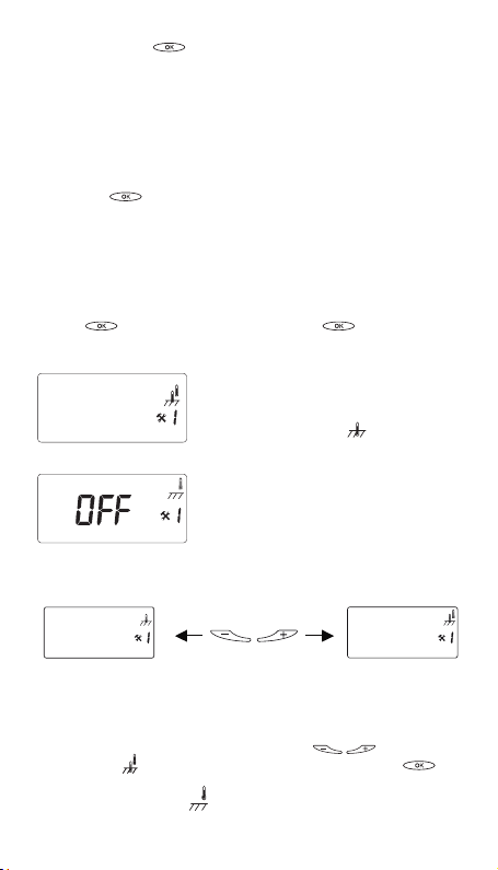
5.3 Installer's menu
Push and hold < > button for 6 seconds to enter
following Menu:
5.3.1 Menu 1: Temperature viewing
• Room sensing mode: Room temperature viewing
(temperature measured inside the thermostat)
• Floor sensing mode: Temperature inside the
cement slab
To check the actual measured temperature, push the
This value can be used to calibrate the floor surface
temperature value to the set temperature value on
the display. Push confirmation button several times
(scroll through Menu structure) to return to Normal
mode
confirmation button for 6 sec.
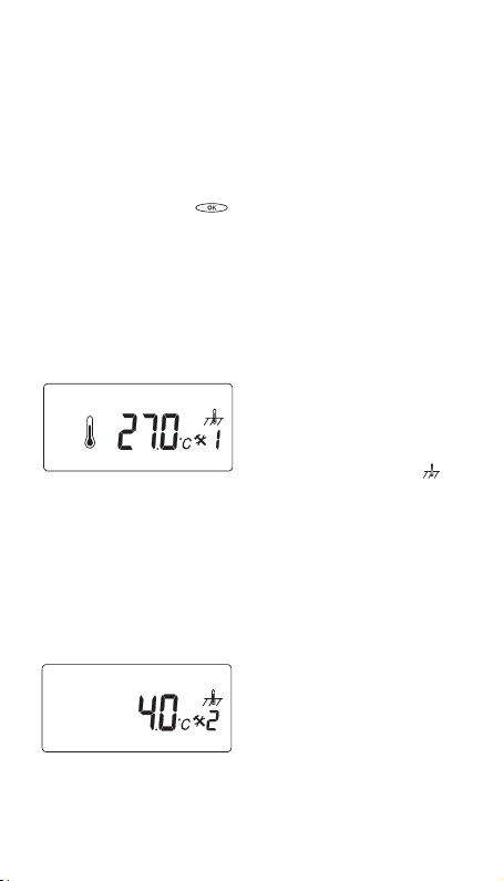
In menu number 1 the
measured temperature value
is indicated on the display:
in-floor temperature in case
of floor sensing mode <
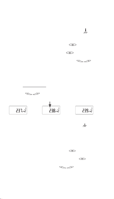
5.3.2 Menu 2: Temperature calibration
Calibration of the temperature set value
If the desired temperature is
not reached or if there is a
difference between real floor/
room temperature and the set
value on the display, calibrate
After stable temperature in floor: The set temperature
value can be calibrated against the real floor / room
temperature. This needs to be done using a separate
20
the thermostat.
>.
thermometer for determining the actual floor or room
temperature. The thermometer should be put on the
floor surface, sensing the floor surface temperature,
or on the wall sensing the air temperature.
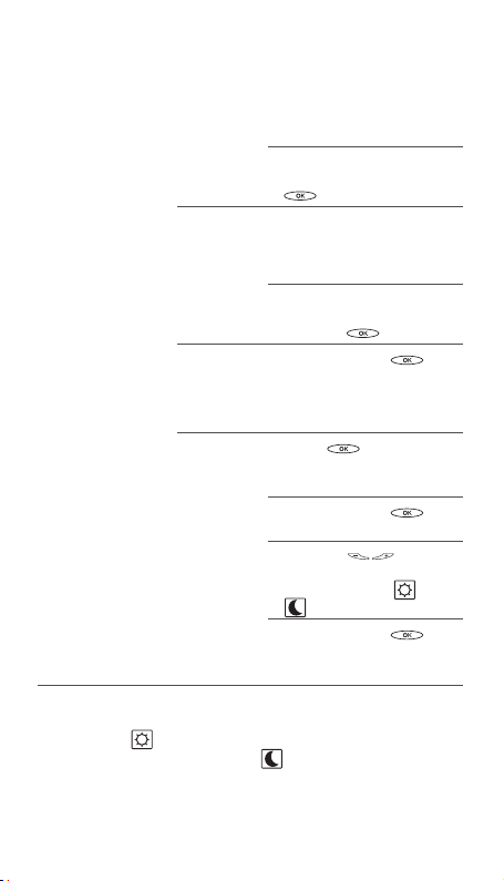
Calibration of room sensor mode < >:
In room sensor mode the internal sensor value is the
same as for the set value on the display.
Push the confirmation button <
enter the Configuration mode.
Push the confirmation button <
number 2.
Change the temperature value via <
buttons to the same value shown on the reference
wall thermometer.
Push confirmation button several times (scroll
through Menu structure) to return to Normal mode
• Room sensor: Room temperature flashing and
possibility to adjust the room temperature with
<
> keys.
> in 6 sec. to
> to enter menu
Initial value to calibrate
Calibration of floor sensor mode < >:
In floor sensor mode there is a default offset value
of +4°C between the infloor sensor value and the
floorsurface value (which is the set value on the
display). The read-out value in Menu 1 can be used
for set value calibration.
Push the confirmation button <
enter the Configuration mode.
Push again the confirmation button <
menu number 2.
Change the offset value via < > buttons so that the
set temperature value will be approx. the same value shown
on the reference floor surface thermometer.
> in 6 sec. to
> to enter
>
21
• Floor sensor: the user can adjust the difference
between the temperature inside the floor and the
room temperature.
Offset = Floor temperature – Room temperature
T
T
menu1
surface
New offset = T
menu 1
- T
surface
Example: Use the floor sensor temperature value
from menu 1. If this value is 27°C and the floor
surface thermometer shows 24°C, the new offset
value will be 27-24 = 3.
Change the offset from 4°C to 3°C.
Push confirmation button several times (scroll
through Menu structure) to return to Normal mode
5.3.3 Menu 3: Delayed Start-Up
The user can choose the time before powering up
the floor warming system.
Possible values: from 0 [OFF] to 15 minutes [15 ’].
A "t" is shown on in the display when the delayed
start-up is switched on.
22
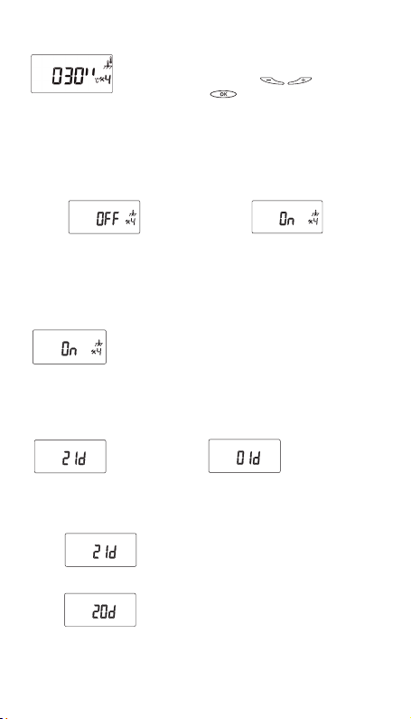
5.3.4 Menu 4: Display backlight "on" duration
Setting of the display backlight.
Change the time with <
Confirm with <
from 0 [OFF] to 120 seconds [120’’] Factory value: 30s
>. Possible values:
> buttons.
5.3.5 Menu 5: "First warming" function
This function can be used for gradual warming of new
screed.
Possible values: [OFF] or [ON]
This function does not apply by default (Installer menu
number 4: OFF by default, factory value = OFF).
Progressive warming cement slab during 21 days
period, but limited to 20°C.
Working description:
When the thermostat comes back to the normal
mode, the user sees instead of the temperature,
the remaining number of days of the progressive
warming (total duration: 21 days).
During this time, the thermostat warming cycle is
equal to 24 minutes (60 cycles per day).
To activate this option the user enters the
installer menu number 4 and selects the
configuration (‘on’ or ‘off’) then presses ok.
Function
remains active
for 21 days.
The first day, the thermostat powers
the floor heating system during 1
minute on each 24 min cycle (= 1h of
warming the first day).
The second day, the thermostat powers
the floor heating system during 2
minutes on each 24 min cycle (= 2h of
warming the second day).
Function
remains active
for 1 day.
23
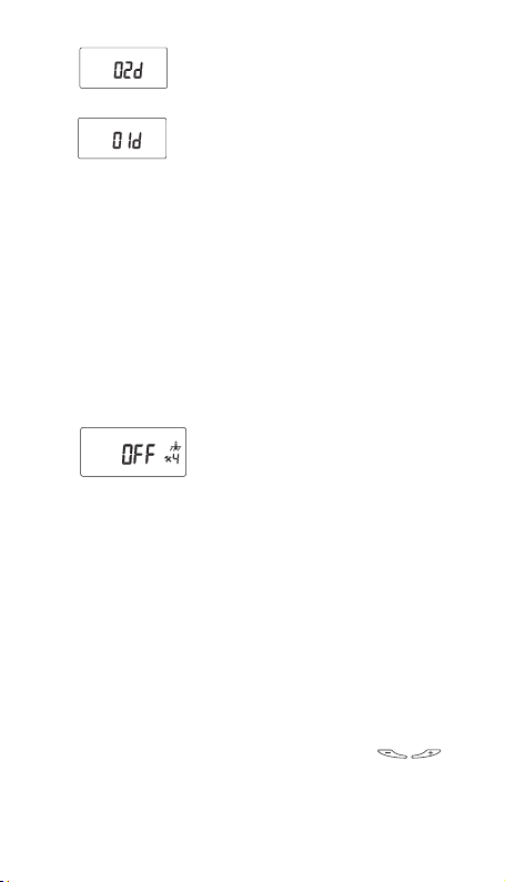
Before the last day, the thermostat
powers the floor heating system during
19 minute on each 24 min cycle (= 19h
of warming the first day).
The last day, the thermostat powers
the floor heating system during
20 minute on each 24 min cycle
(= 20h of warming the first day).
If the thermostat regulation works with the floor
sensor only, the
cement slab temperature will be
limited to 20°C.
If the thermostat regulation works with the room
sensor only, the ambient temperature will be
limited to 20°C.
In both cases of power supply failure or main switch
put on ‘Off’ position by the user during this function
progress, the thermostat will resume from where
it stopped ("First warming" function time saved in
memory).
At the end of this "First warming" function, the learning
function begins if room sensor mode is activated.
This function can be stopped at any
time by setting the installer menu
number 4 to ‘OFF’
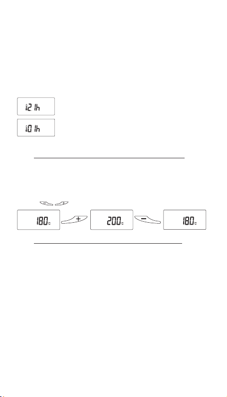
5.3.6 Menu 6: Heating Running Time
Running time (the time in the course of which the
floor warming system is powered)
3’ : 3 minutes
7d : 7 days [1..30]
The sensor mode is detected and initialised
automatically.
If the floor sensor cable is connected, it operates in
floor sensor mode.
To reset this time the user has to press <
simultaneously for more than 3 seconds.
24
[0..59] 5h : 5 hours [1..23]
>

5.3.7 Menu 7: Adjustable switching hysteresis
The switching hysteresis can be adjusted to extended
On/Off cycles: Adjustable: from 0.2 - 2.0°C
Factory setting. 0.5°C
6. OPERATION ECOHOME OR
ECOOFFICE MODE
6.1 Getting started
Note: The function being set is indicated by a square
symbol around the function symbol. Example: If the
square is shown around the clock symbol, the time and
date function may be amended.
The sensor mode is detected and initialised
automatically.
If the floor sensor cable is connected, it operates
in floor sensor mode. To change the sensing mode
to room sensing with floor sensor limiter, see
paragraph 4.2.4. Menu 1.
If the floor sensor is not connected, the NRG-Temp
operates in room sensing mode.
To program the thermostat follow the steps A, B, C
and D below.
The program EcoHome and EcoOffice can be selected as
described on page 12 program selection.
A. Set the time and day < >
“time flashes” Set minutes with < > button.
Press <
“hour flashes” Set hour with <
Press <
“day flashes” Set day with <
Press <
Day 1 is Monday/ Day 7 is Sunday.
Thermostat starts operating in pre-set program
EcoHome or EcoOffice.
Learning function: see page 16.
> to confirm .
> button.
> to confirm.
> button.
> to confirm.
25
B. Edit the timer program < > (EcoHome,
EcoOffice)
Programs overview (Comfort, EcoHome, EcoOffice, Standby)
of the pre-programs annex A page 38
Editable Program
EcoHome,
EcoOffice
Edit e.g.
Program
EcoHome
Program
day 1
Use the <
to scroll through the
menu till P symbol is
active and confirm by
pressing <
EcoHome appears
flashing on the display;
Press and hold <
for 3 seconds to start
programming EcoHome.
Select the desired time
with the <
Press <
Select <
arrows and press <
Go to next time block with
<
Press <
Select <
with arrows and press
>
<
Go to next time block with
<
Press <
Repeat till day 1 is
completely programmed
meaning from 00:00 until
24.00 h
Press <
> buttons
>
>
> buttons.
>
> or < > with
> button
>
> or < >
> button
>
>
>
26
Editable Program
EcoHome,
EcoOffice
Program
day 2
Program
remaining
days
End pro-
gram ming
EcoHome
e.g.
Edit
program
EcoHome
e.g.
If day 2 is different from
the previous day, repeat
the steps as described
in “program day 1”(see
above)
If day 2 is a copy of the
previous day, simply press
>.
<
Program a specific day
by repeating the steps as
described in “program day
1” (see above)
Make a copy of the
previous day simply by
pressing <
Press and hold <
for 3 seconds
Press <
desired day for editing
Press and hold <
for 3 seconds
Edit with <
buttons to set the desired
time and select <
> with cursors
<
Press and hold <
for 3 seconds to end
programming
To “Run” the selected program, choose <AUTO>
mode from the selection. See point D overleaf.
Note: <
temperature mode, the <
> means operation in comfort
> means operation
in reduced temperature mode. These desired
temperatures can be set as described in point C.
>
>
> to select the
>
>
> and
>
27
C. Set the desired comfort temperature and reduced
temperature
Set comfort
temperature
Set reduced
temperature
Adjust the set temperature value
(desired floor or room temperature)
with the <
by pressing <
Press <
value instead of the temperature set
value.
Return to AUTO mode where
the thermostat will then operate
according to the selected program.
Adjust the set temperature value
(desired floor or room temperature)
with the <
by pressing <
Press <
value instead of the temperature set
value.
Return to AUTO mode where
the thermostat will then operate
according to the selected program.
> buttons. Confirm
>.
> again to show the clock
> buttons. Confirm
>.
> again to show the clock
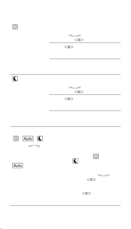
D. Select thermostat mode for normal operation
< , , >
Use the < > buttons to scroll through the menu:
Timer
program
mode
Operation of the selected timer program (see
above) with comfort temperature (
reduced temperature (
override of the temperature in the selected
program, adjust the temperature value (desired
floor or room temperature) with the <
buttons. Confirm by pressing <
override will operate until the next programmed
event when the unit will then resume the
automatic program. Press <
change the view from the clock value to the
temperature view.
). For temporary
) and
>
>. The
> again to
28
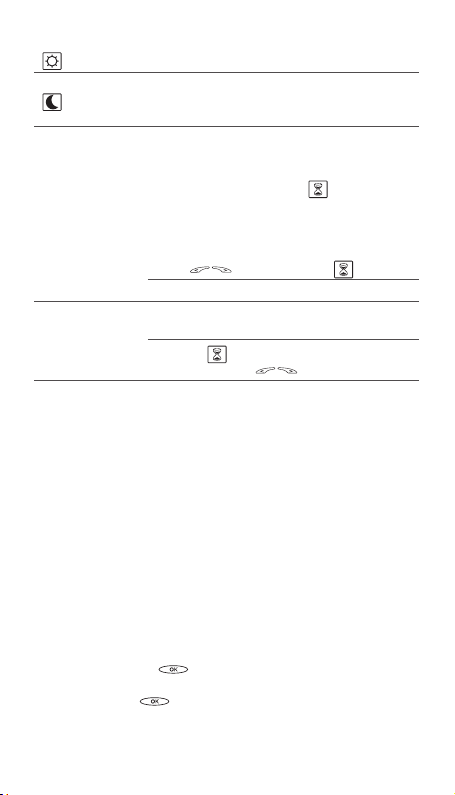
Comfort mode Manual continuous operation of the
Reduced mode
comfort temperature (no program active)
Manual continuous operation of the
reduced temperature (no program active)
e.g. holiday period.
6.2. Optional functions
6.2.1 Activating boost function
< >
This function is used for temporarily increasing the
floor or room temperature by 5°C.
Activate booster
Terminate
booster mode
Use <
Press OK to activate.
Leave unit, as boost function ends
automatically after 2 hours
Or exit <
mode by using <
> to select the < >
> mode and go to another
>
6.2.2 Lock
Lock and unlock the thermostat
It is possible to lock all the parameters of the
thermostat. (e.g. public buildings)
Lock: Press and hold all buttons simultaneously.
Unlock: Press and hold all buttons simultaneously.
6.2.3. Configuration menu
Normal Menu:
In both floor and room sensing mode, the temperature
seen on the thermostat corresponds to the set
temperature.
Viewing rules in each regulation mode (Comfort,
Auto, Reduce and OFF-mode)
By default the view configuration is the set
temperature view.
Pressing the <
temperature value for a duration of 3 seconds.
Pressing <
to setting change.
> button changes the view to actual
> again or left keys changes the view
29
Pressing < > key for 1s switches the view mode
from temperature view to time view.
Exceptions :
• During "First warming" function, the temperature
view is replaced by "First warming" elapse time
counter view.
• During learning function, the temperature view is
replaced by setting temperature value. Pressing
> allows the user to view the elapsed learning
<
period for a duration of 3 seconds.
6.3. Installers's menu
Changing various standard settings of the
thermostat.
To enter following menus push and hold the
> button for 6 sec. Use the < > button
<
to step through the menu’s.
Menu 1: Sensor mode
Menu 1: Sensor regulation choice
If an external sensor is attached, the user is allowed
to choose between 2 regulation modes :
1. Floor sensor only 2. Room with
floor limitation
To change the operating mode to room sensing with
floor sensor as limiter, press the
until <
If the floor sensor is not detected, it operates in room
sensing mode <
30
The sensor mode is detected and
initialised automatically. If the floor
sensor cable is connected, it operates
in floor sensor mode <
If no external sensor is attached the
thermostat works with room sensor
only and the user may not change it.
> is displayed.
>.
< >
Confirm by pressing < >.
>.
buttons
 Loading...