

Pentair Myers WG20 Installation And Service Manual
MODEL WG20
DUPLEX GRINDER PUMPS
INSTALLATION AND SERVICE MANUAL
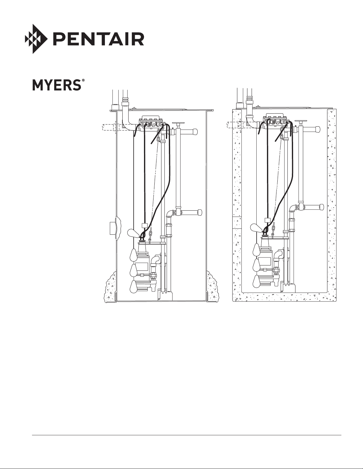
For Myers WG20 Duplex Grinder Pumps with Lift-Out Rail System Installed
in Fiberglass Basin at Factory as Complete System, or Rail Parts for Installing
in Fiberglass or Concrete Basin by Customer.
NOTE! To the installer: Please make sure you provide this manual to the owner of the equip ment or to the responsible
party who maintains the system.
Part # 13800A862 | © 2012 Pentair Pump Group, Inc. | 11/06/12
NOTE – When complete packaged system, including
fiberglass basin, is supplied from factory all parts are
mounted in basin except pump and level controls.
Piping and guide plates for pumps are shipped in
separate packages and must be ordered separately.
Two packages are required for duplex system.
Level controls are to be ordered separately and must
be mounted in basin. Controls are specified at time
of order so proper brackets are mounted in basin for
supporting controls. When mercury float controls are
used, three are required. If optional alarm control is
to be used, it must be specified at time of order so
bracket can be mounted. Control box and pumps are
ordered depending on voltage and phase and if NEMA
3R is required.
CALIFORNIA PROPOSITION 65 WARNING:
This product and related
accessories contain chemicals known to the
State of California to cause cancer, birth
defects or other reproductive harm.
STEPS TO INSTALL RAIL SYSTEM IN
FIBERGLASS OR CONCRETE BASIN
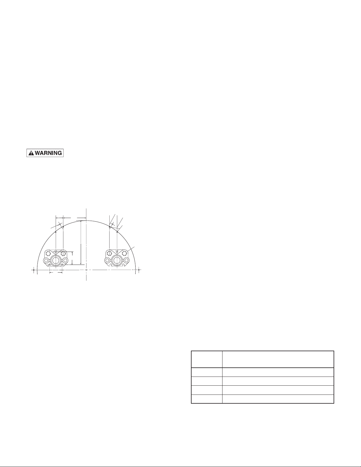
BASIN
11-3/4
19-3/4” CONCRETE BASIN
19-3/16” FIBERGLASS BASIN
48” BASIN
CENTER LINE
BOLT HOLES FOR
BASIN COVER (REF)
2-3/4
4-5/8
4-1/2
PAPER TEMPLATE TO LOCATE DISCHARGE CASTINGS
AND OBTAIN CENTER LINES FOR DISCHARGE AND SUPPORT FLANGES
1. Unpack parts and check that all packages listed
are available. Remove full size paper template to
use in basin bottom to properly locate bolting for
discharge cases and to locate vertical center lines
for flanges. Drop plumb line from cover holes in
basin rim to properly locate base castings.
2. Clean basin bottom thoroughly before placing in
paper template. If basin is concrete, chip out any
protruding rocks. Punch through paper for bolt
hole location. Drop plumb line from top of basin for
center line locations and mark center line on basin
wall with chalk. If basin is fiberglass it must be
mounted on level surface with walls plumb before
marking. All parts should be installed in fiberglass
basin before placing in ground.
3. If basin is concrete, holes must be drilled in
basin bottom and side walls for mounting parts.
Use machine bolt expansion sleeves 1-1/2" long
3/8" size. Use 5/8" carbide drill to drill holes.
If basin is fiberglass, rubber seal washers are
furnished for hold-down bolts.
CENTER LINE DISCHARGE FLANGE
CENTER LINE RAIL SUPPORT FLANGE
DROP PLUMB LINE FROM TOP OF
BASIN TO INTERSECT WITH DOTS
AND MARK CENTER LINES ON
WALL OF BASIN SO THAT
FLANGES CAN BE MOUNTED AT
PROPER HEIGHT
SET DISCHARGE CASTING ON
PAPER TEMPLATE AND PUNCH
THROUGH MOUNTING HOLES
TO LOCATE DRILLING FOR
EXPANSION BOLTS.
4. Cut holes through concrete wall or fiberglass basin
wall to locate discharge and support flanges. Pipes
can be cemented into wall instead of using flanges
if desired.
5. Bolt discharge cases to basin bottom. If basin is
fiberglass, seal washers are furnished to seal bolt
heads where bolts pass through basin bottom. Bolt
all flanges in place. Do not tighten bolts completely
tight at this stage as some adjustment may be
necessary when rails are placed.
6. Install discharge piping from base casting to
discharge flange. Be sure vertical piping is plumb
so that it will not interfere with the rail guide
pipes. Use slip coupling to join pipes.
7. Install 1" galv. pipe rails. Stainless steel or other
corrosion resistant pipe may be used as long as
the O.D. is same as 1" std. pipe, 1.315" O.D.
In order to mount the rail support bracket it may be
necessary to place the yoke in the rails, then push
the support nipple through the yoke and screw
into mounting flange. Bolts can be loosened in the
flange to allow alignment if necessary. If pipe
is cemented in, be sure all piping is in place and
plumbed and blocked before final cementing.
8. Align 1" rails plumb by using a level in both
directions on pipe. Adjust rail support yoke if
necessary. Once rails are properly aligned, tighten
all bolts in base castings and flanges.
9. Mount level control support brackets
and install level controls on brackets and
set SM25NO controls at proper levels.
10. If basin cover is used where control box is
mounted directly on cover, attach aluminum
connection box to 2" elbow supplied with cover
before mounting cover to basin.
11. Place cover on basin and bolt in place. If basin
is concrete, expansion sleeves must be installed
at proper bolt locations.
12. Inlet flange must be mounted to basin at depth
required to get gravity flow into basin. Flanges are
available for 4", 6" or 8" pipe and more than one
inlet can be used if required. Inlet hole is cut and
flange is mounted in the field.
Cubic feet of concrete poured around basin to
prevent flotation.
BASIN
DIA.
24" 2
30" 3.5
36" 5
48" 8.5
CUBIC FEET OF CONCRETE REQUIRED
PER FOOT OF BASIN DEPTH
Example – 24" dia. basin 8 ft. deep requires
2 x 8 = 16 cu. ft. of concrete to prevent flotation. If
basin is installed in dry ground without surface water,
1/3 of above values may be used.
13800A862 11/06/12
2

ASSEMBLING PIPING TO PUMP
Pump grinder plate and pump discharge piping is
supplied with other rail parts.
1. Attach guide plate and piping to pump. Be sure
piping is plumb, then tighten all set screws. Attach
lifting chain to lifting eye with clevis supplied.
Pumps can now be lowered into position with
lifting chain. Retain power and control cords at
surface as pump is lowered.
When pumps are in place, attach cords to
connection box. Remove slack from wires so that
they will hang vertical without tangling.
2. Connect level control cords to connection box as
shown on wiring diagrams.
3. Install control box on cover and connect to cover
with 2" conduit as shown.
4. Run wires to control box and connect to cords
coming into connection box. Mark or trace each
incoming wire so that it can be connected to
proper cord.
5. Do not pour sealing compound into fitting
until pumps have been run, to be sure all
connections are correct.
NOTE – If control box is to be installed, off-set from
basin. The CF-200 conduit flange must be installed in
basin and connection box to be connected to flange
before installing cover.
6. Install hold-down guides and 1/2" galv. holddown pipe. Screw pipe into lower guide. Upper
guides fasten to rails and hold-down pipe with
set screws. The hold-down pipe is necessary to
prevent hydraulic pressure from lifting pump from
base seal casting. The hydraulic pressure keeps
the pumps suspended when in operation so there
is no side load on the rails and removal is easier
when required.
7. Valve adapter and shut-off handles are connected
with 1/2" galv. pipe and held with set screws.
These shut-off stems are installed in 1-1/2" plastic
pipe guides attached to valves.
STARTING SYSTEM
1. Open 1-1/4" bronze gate valves; turn counterclockwise to open.
2. Set pump switches on Auto position and run water
into sump until level controls starts one pump.
Allow pump to operate until sump level drops,
stopping pump.
come on and operate until sump level drops to the
Off position.
4. Leave both pump switches to Off and fill sump
until level is to override control, then turn both
pump switches to Auto position. Both pumps
should come on and operate until sump level
drops to the Off position.
5. Leave both pump switches to Auto position and
system is now ready for automatic operation.
IN CASE OF TROUBLE CHECK
THE FOLLOWING:
Pumps will run but not deliver water.
1. Probably air lock. Start and stop pump several
times. If this does not clear air turn both pumps
to Off and run more water into sump 6" to 12"
higher. If air still does not clear it may be necessary
to raise hold-down pipe and lift pump so that
lower seal fitting is out of the discharge case to
release air.
2. Be sure shut-off valve is open in discharge line.
3. If pump is 3 phase be sure rotation is correct.
Grinder impeller must rotate counterclockwise
when looking at pump inlet. Do not put fingers
near grinder impeller.
Pump seal fitting does not hold tight.
1. Probably cut or broken O-ring. Replace if
necessary. Trash may be caught in seal flange.
Lift pump and open shut-off valve to back flush
discharge casting.
On installation where discharge line is not
filled it may be necessary to lift pump until seal
flange is out of discharge case, then run pump
to flush casting.
For all other trouble problems with pump or control
box refer to pump and control box instructions
included with these items.
CAUTION – Never work on pumps or controls
unless power is turned off. If pump is remote from
control box, disconnect wires to pumps to be
certain power cannot be turned on when working
on pumps. Never put fingers near grinder impeller
when pump cord is connected.
IMPORTANT – Lower level control or weight should
be set so that sump level drops to within 1" or 2" from
bottom of pump before stopping pump.
3. Turn both pump switches to Off and fill sump until
level is to override control, then turn both pump
switches to Auto position. Both pumps should
3
13800A862 11/06/12
MYERS DUPLEX LIFT-OUT RAIL SYSTEM IN 36" OR 48" CONCRETE BASIN
CENTER LINE OF
RAIL SUPPORT FLANGES
HOLDING CLAMPS AND
SUPPORT BRACKET
FOR SHUT-OFF GUIDE PIPE
YOKE LOCKING
SET SCREWS
L
FROM C OF SUPPORT FLANGE TO BOTTOM OF BASIN
LENGTH OF 1” GALV. PIPE RAILS – 1” LESS THAN LENGTH
36” BASIN
48” BASIN
WITH PARTS TO LOCATE DISCHARGE CASTING
11-1/4
14-1/2
17-3/8” FOR 36” BASIN
USE PAPER TEMPLATE FURNISHED
AND FLANGES
RAIL SUPPORT FLANGE
RAIL SUPPORT
YOKE
GUIDE RAILS
1” GALV. PIPE
(BY OTHERS)
DISCHARGE
FLANGE
RAIL LOCKING SET SCREWS
18-1/4” FOR 48” BASIN
8-1/2
11-3/4
36” BASIN
48” BASIN
CENTER LINE OF DISCH.
PIPE FLANGES
USE SOFT RUBBER GASKET,
SUPPLIED, BEHIND FLANGES
1-1/4 GALV. PIPE PLUG
ELEV.
GROUND SURFACE
2” CONDUIT TO
CONTROL BOX
(BY OTHERS)
ELEV.
ELEV.
36” OR 48” CONCRETE PIPE BASIN OR MANHOLE
10”
2” FLANGE TO CONNECT
WATERPROOF
CONNECTION BOX
(USE ONLY IF
CONTROL BOX IS
MOUNTED REMOTE
FROM SUMP)
INVERT
36” MINIMUM
5”
1-1/4 GALV NIPPLE
THREAD ONE END
X 10” LONG
1-1/4 BRONZE
VALVE
1-1/4 x 6” GALV.
NIPPLE
1-1/4 x 3” GALV.
NIPPLE
GUIDE RAILS
1” GALV. PIPE
(BY OTHERS)
DEPTH OF BASIN TO SUIT INSTALLATION
DISCH. PIPE
1-1/4 GALV.
(BY OTHERS)
DISCHARGE
CASTING
VALVE SHUT-OFF STEM
RAIL SUPPORT
YOKE
SUPPORT
FLANGE
1-1/2” P.V. C. SCHED.
40 PIPE FOR
SHUT-OFF GUIDE
(BY OTHERS)
DISCHARGE
FLANGE
L
BOTTOM OF BASIN
LENGTH OF DISCH. PIPE
FROM C OF DISCH. PIPE TO
12-1/4” LESS THAN LENGTH
BELOW FROST LINE
DEPTH TO SUIT INSTALLATION
DISCHARGE
C
L
1-1/4 PIPE
(BY OTHERS)
L
C DISCH. TO BOTTOM OF BASIN
3/8-16 x 2” LG. MACHINE BOLTS & ARRO 3500 SERIES 1-1/2” LG. EXPANSION SLEEVES (TOTAL REQUIRED 32 EACH, BY OTHERS)
USE RUST PROOF PLATED BOLT S AND SLEEVES (WASHERS ARE FURNISHED)
13800A862 11/06/12
4
 Loading...