

Pentair Myers SX Series, Myers SX50, Myers SX50H, Myers SX150H, Myers SX200H Installation And Service Manual
The submersible SX Series pumps are CSA approved for
use in Class I, Division 1, Group D hazardous locations in
wastewater and storm water applications. The SX Series
pumps are not intended for applications requiring
the pumping of flammable liquids. A triplex system is
recommend to reduce the possibility of concentrations of
flammable/hazardous liquids entering the main lift station.
SX SERIES
(Class I, Division 1, Group D)
INSTALLATION AND SERVICE MANUAL
NOTE! To the installer: Please make sure you provide this manual to the owner of the equip ment or to the responsible
party who maintains the system.
Item # 23833A465 | © 2016 Pentair plc | 09/29/16
WARNING! IMPORTANT SAFETY INSTRUCTIONS! READ CAREFULLY BEFORE INSTALLATION.
This manual contains important information for the safe use of this product. Read this manual
completely before using this product and refer to it often for continued safe product use. DO NOT
THROW AWAY OR LOSE THIS MANUAL. Keep it in a safe place so that you may refer to it often.
DANGER: Risk of Electrical Shock or Electrocution. May
result in serious injury or death or fire hazard. Installer
must disconnect all electrical sources prior to installation,
handling or servicing. Only qualified personnel may
install this system. NFPA 70/National Electric Code
(NEC) or local codes must be followed. System must be
properly grounded according to NEC. Do not lift pump by
power cord.
DANGER: Biohazard Risk. Once wastewater source
has been connected to system, biohazard risk exists.
Installer(s) and/or service personnel must use proper
personal protective equipment and follow handling
procedures per OSHA 29 CFR 1910.1030 when handling
equipment after wastewater source has been connected
to system.
DANGER: Risk of Asphyxiation. Installer(s) and/or service
personnel must use proper personal protective equipment
and follow OSHA 29 CFR 1910.146 or OSHA 29 CFR
1926. Pump may be installed in a location classified as a
confined space.
DANGER: Risk of Fire or Explosion. Do not
smoke or use open flames in or around this system. This
system is not intended for use in hazardous locations per
NFPA 70 National Electric Code. Do not pump flammable
liquids. Consult factory for optional equipment rated for
hazardous location use.
10. Only qualified personnel should install, operate or
repair pump.
11. Keep clear of suction and discharge openings. DO NOT
insert fingers in pump with power connected.
12. Do not pump hazardous material not recommended for
pump (flammable, caustic, etc.).
13. Make sure lifting handles are securely fastened each time
before lifting.
14. Do not exceed manufacturer's recommendation for
maximum performance, as this could cause the motor
to overheat.
15. Secure the pump in its operating position so it cannot tip
over, fall or slide.
16. Keep hands and feet away from impeller when power
is connected.
17. Submersible pumps are not approved for use in swimming
pools, recreational water installations, decorative fountains
or any installation where human contact with the pumped
fluid is common.
18. Do not operate pump without safety devices in place.
19. For hazardous locations, use pumps that are listed and
classified for such locations.
IMPORTANT! Myers is not responsible for losses, injury
or death resulting from a failure to observe these safety
precautions, misuse or abuse of pumps or equipment.
CALIFORNIA PROPOSITION 65 WARNING:
This product and related accessories
contain chemicals known to the State of California to
cause cancer, birth defects or other reproductive harm.
GENERAL
1. Most accidents can be avoided by using
COMMON SENSE.
2. Read the operation and maintenance instructions manual
supplied with the pump.
3. Do not wear loose clothing that can become entangled in
the impeller or other moving parts.
ELECTRICAL
4. To reduce risk of electrical shock, disconnect the pump
from the power source before handling or servicing.
5. Any wiring to be done on pumps should be done by a
qualified electrician.
6. Never operate a pump with a power cord that has frayed
or brittle insulation.
7. Never let cords or plugs lie in water.
8. Never handle connected power cords with wet hands.
PUMPS
9. Pump builds up heat and pressure during operation; allow
time for pump to cool before handling or servicing.
Motor HP & Voltages: The SX Series pumps are offered in
single and three phase. Voltages will vary according to the
application, for details consult factory.
Electrical Controls: All of these pump models must be used
with a control panel. Myers built control panels are designed
to supply the correct electrical controls, motor starting
equipment and include the circuitry for moisture and heat
sensors. It is recommended that a Myers built control panel be
used so that all warranties apply.
General Construction: The SX Series motor construction
is designed to meet CSA requirements for Class I, Group D
sewage applications. The motor chamber and seal chamber
are filled with a high dielectric type oil for improved lubrication
and heat transfer of the bearings and motor. An air space
above the oil level in both the seal and motor chambers
is provided to allow for the expansion of the oil when at
operating temperature. The power and control lines are sealed
and strain relieved on the outside entrance with a standard
cord grip, and internally through the use of a dielectric potting
resin surrounding the electrical wires.
General Installation: Various configurations and methods of
plumbing this series may be used.
Note: If the SX Series hazardous location pumps are used
in conjunction with a rail lift-out system, it must be a listed or
recognized nonsparking system for hazardous locations.
2

These pumps are to be used for handling septic tank effluent,
sewage, and storm water only. Do not use in other hazardous
locations. These motors must be repaired and serviced only at
a Myers authorized service center or at the Myers factory. Any
unauthorized field repair voids warranty and the hazardous
location rating.
CAUTION: Sewage water gives off methane and hydrogen
sulfide gases, which are poisonous. It is for this reason
that Myers recommends using the rail lift-out system so
that no service is required inside the basin.
rotating pump will torque counterclockwise upon start.
ALWAYS CHECK THREE PHASE PUMPS FOR PROPER
ROTATION BEFORE INSTALLING PUMPS.
The control cable has 5 conductors – black, white, red, orange
and green. White and black connect to the heat sensor
terminals in the control panels; red and orange connect to
the seal failure terminals in the control panel; and the green
connects to the ground in the control panel.
Motor: Each motor is provided with heat sensor thermostats
attached directly to the motor windings. The thermostats open
if the motor windings see excessive heat and, in turn, open
the motor contactor in the control panel, breaking the power
to the pump. When the motor is stopped due to an overheat
condition, it will not start until the motor has cooled and the
heat sensor reset button is manually pushed on the front of
the Myers control panel. This circuitry is provided in the Myers
control panel designs.
The SX Series pumps are equipped with internal thermostats.
Note: Failure to use proper circuitry and to connect the motor
overheat protection in the control panel would negate all
warranties and CSA Listings.
Motor Seal Failure Warning: The seal chamber is oil filled
and provided with moisture sensing probes to detect water
leakage through the lower shaft seal. The probes can also
detect moisture present in the upper motor housing.
The presence of water energizes a red seal leak warning light
at the control panel. This is a warning light only, and does
not stop the motor. It indicates a leak has occurred and the
pump must be repaired. Normally, this indicates the outboard
seal has leaked. Allowing the unit to operate after the warning
could cause upper seal leakage along with motor failure.
On the Myers control panels the seal leak test switch tests
the seal leak circuit continuity. When pushed the seal leak test
bulb should light. If the test bulb does not light it means either
the wiring circuitry to the seal leak probes have been broken
or the bulb has burned out.
Note: Myers built control panels supply the correct circuitry
for moisture and heat sensor connections. Failure to install the
correct circuitry with proper connection would negate warranty
and CSA Listing.
Motor Power Cord, Control Cord and Cord Cap Assembly:
Each motor power cord has 4 conductors – white, black, red
and green. For a single phase motor the black is connected
to the common lead, the white is connected to the main lead,
while the red is connected to the start circuitry, and the green
is attached to a good ground. The rotation of a single phase
pump is set properly at the factory.
The control and power cables cannot be spliced!
Note: Each cable has a green ground wire and must be
properly grounded per the National Electric Code and
local codes.
Electrical Motor Controls: All electrical controls and motor
starting equipment should be specified from factory. Consult
factory for any acceptable alternatives. For hazardous
locations the controls and control panel must be installed
outside the hazardous area. Only approved controls that are
intrinsically safe may be used with these pumps.
Junction Box: If a junction box is used in a hazardous
location, it must be an approved type with approved cord
connectors. Wires from the junction box must pass through an
approved seal connector for hazardous locations.
Level Sensing Controls: Intrinsically safe-type float controls
are recommended for all applications and required for
hazardous locations. An intrinsically safe control panel relay
will limit the current and voltage to the level controls. A Myers
control panel can be supplied with this type circuitry. The
float level controls maintain the basin sewage water level by
controlling pump turn-on and turn-off levels.
1. The lower turn-off control should be set so that the pump
stops with the water covering the entire motor housing.
Consult the factory for any settings below this point.
2. The upper turn-on control should be set above the lower
turn-off control. The exact height between the two controls
is determined by the number of pump starts desired and
the depth of the basin. A maximum of 10 starts per hour
should not be exceeded.
3. The override control is set at a specified height above the
upper turn-on control.
4. The alarm control is set about 6" to 12" above the
override control.
5. No control should be set above the inlet invert.
Electrical Connections: Complete wiring diagrams are
included for use in making the installation. All wires should be
checked for shorts to ground with an ohmmeter or megger
after the connections are made. This is important, as one
grounded wire can cause failure of the pump, control panel or
personal injury.
For three phase motor, the black, white, and red conductors
are power leads and the green is ground.
Note: Rotation should be clockwise when observed from
the top of the pump. This can be checked by noting which
direction the pump torques upon initial starting. A properly
3

TROUBLESHOOTING
CONDITION
Red light comes on at control box.
Overload trips at control box and alarm buzzer or flashing red light
comes on due to high water level in basin.
Yellow run light stays on continuously.
Circuit breaker trips.
PROBABLE CAUSE
This indicates some water has leaked past the lower seal and has
entered the seal chamber and made contact with the electrode
probe. Pump must be removed for replacement of lower seal. This
preventive repair will save an expensive motor.
1. Push in on red reset button to reset overload. If overload trips
again after short run, pump has some damage and must be
removed from basin for checking.
2. Trouble may be from clogged impeller causing motor to overload
or could be from failed motor.
3. Trouble may be from faulty component in control box. Always
check control box before removing pump.
1. Indicates H-O-A switch may be in the Hand position.
2. Level control switch may have failed causing pump to continue to
operate when water is below lower control.
3. Impeller may be partially clogged causing pump to operate at very
reduced capacity.
4. Gate valve or check valve may be clogged causing low pump flow.
5. Pump may be air locked.
1. Reset breaker by pushing completely down on handle then back
to On position. If breaker trips again in few seconds it indicates
excessive load probably caused by a short in the motor or control
box. Check out instructions given with control box before pulling
pump.
2. If this condition happens after an electrical storm, motor or control
box may be damaged by lightning.
3. Resistance reading of the motor with lead wires disconnected
from the control box can determine if trouble is in motor or control
box.
Pump is noisy and pump rate is low.
Grease and solids have accumulated around pump and will not pump
out of basin.
1. Impeller may be partially clogged with some foreign objects
causing noise and overload on the motor.
1. Lower control switch may be set too high.
2. Run pump on Hand operation for several minutes with small
amount of water running into basin to clean out solids and grease.
This allows pump to break suction and surge which will break up
the solids. If level switch is set properly this condition generally
will not occur.
3. Trash and grease may have accumulated around floats causing
pump to operate erratically.
CAUTION – DISCONNECT ALL POWER AND CONTROL WIRES TO MOTOR AT CONTROL PANEL BEFORE
STARTING DISASSEMBLY OPERATIONS. NEVER RELY ON OPENING CIRCUIT BREAKER ONLY.
4
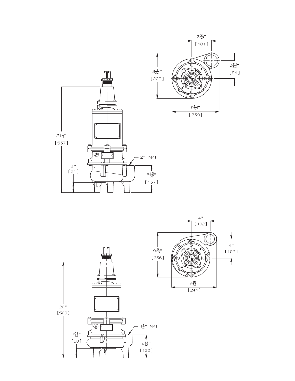
SX50 DIMENSIONS
[Dimensions in mm]
SX50H, SX150H and SX200H DIMENSIONS
[Dimensions in mm]
5
 Loading...