

Page 1
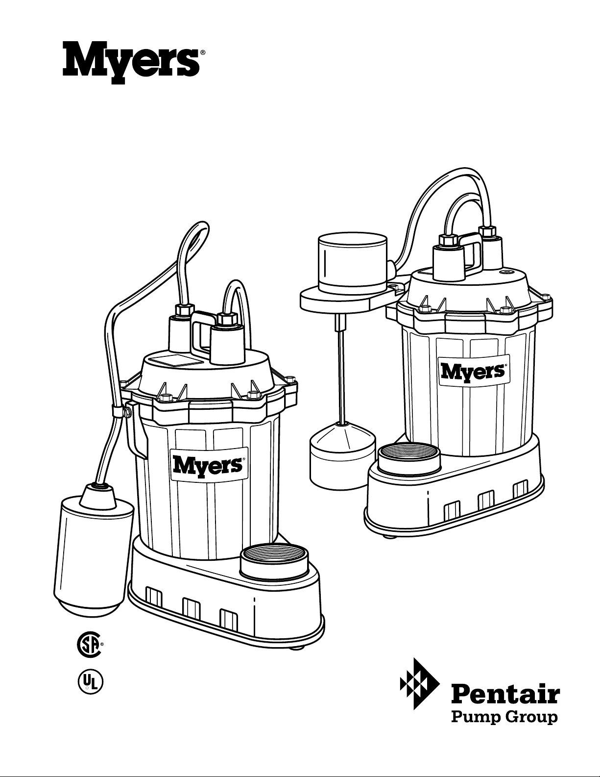
S33 Sump Pump
INSTRUCTIONS AND SERVICE MANUAL
VERTICAL
FLOAT SWITCH
S33V1 & S33V1C
AUTOMATIC
S33P1 & S33PC-1
(CONTROL WITH SERIES PLUG)
NOT SHOWN
AUTOMATIC
S33A1 & S33A1C
R
23833A587 Bag #18812A108
Page 2
P. 3
23833A587 Bag #18812A108
WARNING risk of electric shock. This pump is supplied with a grounding conductor and grounding-type attachment plug.
To reduce the risk of electric shock, be certain that it is connected only to a properly grounded, grounding-type receptacle.
Pumps can be installed with ABS, PVC or polyethylene plastic pipe, or galvanized or copper pipe. Proper adapters are required to
connect plastic pipe to pump.
The discharge is threaded for 1-1/2 inch pipe. NOTE: DO NOT OVERTIGHTEN DISCHARGE PIPE INTO PUMP PLASTIC
DISCHARGE FITTING.
A CHECK VALVE MUST BE USED IN THE DISCHARGE LINE FOR ALL PUMPS. A shut-off valve should be used. Always install check
valve with arrow on body in direction of ow.
AIR LOCKING
A sump pump is said to be air locked if water traps air in the pump and it cannot get out, thus preventing
pump from operating.
All Myers sump pumps have a small air vent hole in the impeller chamber to let out trapped air. If this hole
becomes plugged, pump may air lock. This usually happens on pumps that are used mainly in the wet seasons.
In summer months,the pump may be turned off as sump water dries up. When pump is turned on again and
water comes up in the sump, the air will trap in pump if not vented.
AS A SECONDARY PRECAUTION IN INSTALLATIONS OF THIS TYPE, EXAMPLE: TYPE “A” 1/8" HOLE SHOULD BE DRILLED IN THE
DISCHARGE PIPE BELOW THE CHECK VALVE. THE CHECK VALVE SHOULD BE 12 TO 18 INCHES ABOVE PUMP DISCHARGE. DO
NOT PUT CHECK VALVE DIRECTLY INTO PUMP DISCHARGE OPENING.
In normal sumps where the pump is operating daily, air locking rarely occurs.
P. 2
23833A587 Bag #18812A108
Page 3

PUMP
MODEL
TOTAL HEAD (vertical pumping distance) IN FEET
S33
PERFORMANCE TABLE (in gallons per minute)
63383010
29122714251623181720152212
22
2
IMPORTANT INSTRUCTIONS BEFORE INSTALLATION
Failure to follow these instructions may cause serious bodily injury and/or property damage.
Warranty void if product modied, drilled, painted,
or altered in any way; if used to pump hot water,
or to pump liquids other than water (such as but
not limited to chemicals, fertilizers, ammable
liquids, herbicides, mud, tar, cement, wood chips); or
otherwise abused.
WARNING, risk of electric shock – This pump is supplied
with a grounding conductor and grounding-type attachment
plug. To reduce the risk of electric shock, be certain that it
is connected only to a properly grounded, grounding-type
receptacle. This pump has not been investigated for use in
swimming pool areas. DO NOT WORK ON PUMP UNTIL POWER
IS UNPLUGGED. DO NOT cut off ground pin or use an adapter
tting. DO NOT use an extension cord. The pump power
cord should be connected to a separately fused, grounded
115 volt line with a capacity of 15 amps. NEVER touch the
pump when it is connected to electrical power.
1. Before installing or servicing your pump, BE CERTAIN
pump power source is disconnected.
2. Installation and electrical wiring must adhere to state
and local codes and must be complete before priming pump.
Check appropriate community agencies, or contact local
electrical and pump professionals.
3. CALL AN ELECTRICIAN WHEN IN DOUBT. Pump should be
connected to a separate 15 amp circuit breaker or 15 amp fuse
block. Plugging into existing outlets may cause low voltage
at motor, causing blown fuses, tripping of motor overload,
or burned out motor.
4. A permanent ground connection from pump to the
grounding bar at the service panel is mandatory. Myers sump
pumps come with a grounding conductor and a groundingtype attachment plug. Do not connect pump to a power
supply until permanently grounded. For maximum safety,
ground pump to a circuit equipped with a fault interrupter
device.
5. Voltage of power supply must match the voltage of the
pump. All Myers sump pumps are factory preset to
115V, 60Hz.
6. Before installing pump, clear sump basin of any water,
debris, or sediment.
WARNING: Sump basin must be vented in accordance
with local plumbing codes. Myers sump pumps are not
designed for and CANNOT be installed in locations
classied as hazardous in the National Electric Code,
ANSI/NFPA 70.
7. The sump basin should be between 14" and 18" in
diameter for the S33A1, S33P-1, S33A1C, S33PC-1, S33M1C
and 12"–18" for the S33V1, S33V1C, S33PV1 made of plastic,
berglass, or concrete.
8. The following may cause severe damage to pump and will
void warranty:
• Using the pump without a check valve.
• Using an extension cord.
• Cutting off the ground pin or using an adapter tting.
• Working on pump or switch while plugged in.
• Removing motor housing, unscrewing impeller, or
otherwise removing impeller seal.
• Running the pump continuously.
• Pumping chemicals or corrosive liquids.
• Pumping gasoline or other ammable liquids.
PIPING
Plastic PVC pipe is shown in the illustrations, but drain
hose, galvanized steel or copper pipe may be used if desired.
All piping must be clean and free of all foreign matter to
prevent clogging. Use thread compound on all threaded
joints unless specied otherwise.
9. Do not open pump housing to attempt repair–this will
cause a severe shock hazard.
10. Any nished basement or living area should be equipped
with a sump pump alarm to warn of a pump failure and
protect against water damage.
A CHECK VALVE MUST BE USED IN THE DISCHARGE LINE FOR ALL PUMPS. A shut-off valve should be used. Always install
check valve with arrow on body in direction of ow.
PUMP MOTOR
NEVER REMOVE MOTOR HOUSING OR UNSCREW PUMP IMPELLER. Warranty on pump is void if motor housing, impeller or seal have
been removed. Any repair on motor must be done by an authorized Myers service center.
23833A587 Bag #18812A108
11. Cycle the pump at least once per month when regular
use isn’t occurring.
12. Always use a properly installed check valve with this
sump pump.
P. 3
Page 4

P. 5
23833A587 Bag #18812A108
5"
COMPLETE SUBMERSIBLE SUMP PUMP INSTALLATION
3-5/8" Minimum
Refer to the installation illustrations below and on the
following page for the following instructions. Be certain
sump basin is clean and all power to pump is shut off.
If pump fails to operate properly after installation, refer
to the troubleshooting checklist on page 6 or contact your
STEP
1
Thread male PVC adapter into pump
discharge opening.
STEP
2
Cement a 15" piece of PVC pipe to adapter. Use
appropriate diameter piping. Drill a 1/8" relief
hole in the pipe 5" above pump connection.
This hole prevents pump from air-locking.
Myers distributor. All parts with part numbers are
quality Myers parts.
Tools Needed for All Pump Installation
Pipe wrench, slot screwdriver, hacksaw, round le, drill,
1/8" drill bit, pvc cement.
or
Retrot
STEP
3
STEP
4
STEP
5
Clamp Check Valve to top of 15" PVC pipe with
water ow arrow pointing away
from pump.
Lower pump into basin. Clamp needed PVC
discharge pipe and ttings to open end of
Check Valve.
Fill sump basin with water and plug in pump.
Perform several ON-OFF cycles to assure
satisfactory operation.
23833A587 Bag #18812A108
P. 4
Page 5

STARTING PUMP - S33A (AUTOMATIC)
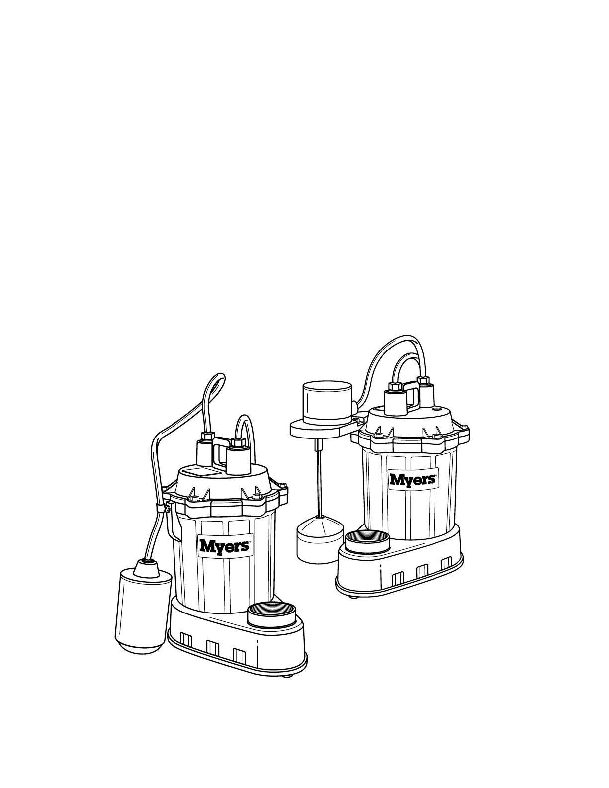
1. These pumps have an integral mechanical (mercury-free) ball oat switch as shown on installation drawing. “Vertical switch”
models have a vertical actuated cylinder oat.
2. Plug cord into a 115 volt GROUNDED RECEPTACLE.
3. Run water into sump until pump starts.
4. Allow pump to operate through several on-off cycles to be sure operation is satisfactory.
5. If shut-off valve is used in discharge line, be sure valve is open.
6. If pump does not operate properly, see trouble service chart for remedy. NOTE: TETHER LENGTH OF SWITCH CORD ON BALL
FLOAT MUST BE MINIMUM OF 3-5/8" AS NOTED IN INSTALLATION STEP 1, PAGE 4.
USING THE S33M SUMP PUMP FOR MANUAL OPERATION
The pump cord for these units can be plugged directly into proper GROUNDED RECEPTACLE for continuous pump operation.
CAUTION: THIS TYPE OF OPERATION SHOULD BE USED ONLY FOR EMERGENCY USE OR WHERE A LARGE VOLUME OF WATER
IS TO BE PUMPED, SUCH AS FLOODED BASEMENT.
PUMP MUST NOT BE RUN CONTINUOUSLY OUT OF WATER. NOTE: RUNNING PUMP CONTINUOUSLY WILL VOID WARRANTY.
DO NOT USE WITH EXTENSION CORD.
AUTOMATIC/MANUAL MODEL
The Model S33 sump pump can be changed from one style, Automatic or Manual, to the other by interchanging only the plug ends
of the oat control with the manual plug. The ball oats must be tethered with a cable clamp, as shown. DO NOT REMOVE THE
MOTOR CAP.
HOW MECHANICAL SWITCH FLOAT OPERATES
This level control uses a mechanical switch sealed in a polypropylene oat cylinder. The switch is not position sensitive; that is, it will
operate regardless of position.
When level rises in the sump, the cylinder oats up with the level. When the cylinder position is at an angle of about 45º, the steel
ball rolls over a detent and actuates the switch. This starts the pump motor.
As the sump level draws down, the cylinder oats down and when it is again at an angle of about 45º, the steel ball drops away,
deactivating the switch and the motor stops.
BE SURE CYLINDER FLOATS FREELY IN SUMP BASIN WITHOUT TOUCHING THE BASIN WALLS. ADJUST PUMP POSITION IN
SUMP IF NECESSARY.
PUMP MOTOR
NEVER REMOVE MOTOR HOUSING OR UNSCREW PUMP IMPELLER. Warranty on pump is void if motor housing, impeller or seal
have been removed. Any repair on motor must be done by an authorized Myers service center.
MAINTENANCE AND SERVICE
If pump does not operate properly, follow steps shown on servicing chart. If trouble cannot be located with these steps shown, call
Myers service dealer, or take pump to Myers authorized service center.
CAUTION: FOR ANY WORK ON PUMP OR SWITCH, ALWAYS UNPLUG POWER CORD.
CLEANING FLOAT
If pump becomes inoperative because of accumulation of trash on the oat, remove from sump and clean oat.
1. Wipe all water and dirt from pump and oat and also the vertical rod on vertical models.
2. Be sure oat operates freely after cleaning.
CLEANING IMPELLER AND VOLUTE CASE
1. Remove (3) screws that hold bottom plate to volute case.
2. Remove (4) screws that hold volute case to metal motor housing.
3. Use screwdriver to pry plastic case from metal housing. Use care not to gouge groove in the plastic. Pry in several spots to loosen.
4. Remove volute case and clean impeller and volute passage.
5. Be sure impeller turns freely after cleaning.
6. Clean out holes in plastic pump base and wash thoroughly before replacing.
7. DO NOT UNSCREW IMPELLER.
23833A587 Bag #18812A108
P. 5
Page 6

P. 7
23833A587 Bag #18812A108
Service
Chart
SOLUTIONS
Line circuit breaker may be off, or fuse, if used, may be blown or loose.
Water level in sump may be too low. Run in more water. Turn-on level is 12 to
13 inches above sump bottom.
Pump cord plug may not be making contact in receptacle.
If pump is using the series cord plug, the two plugs may not be plugged
tight together.
Float may be stuck. Be sure oat operates freely in basin.
If all symptoms check OK, motor winding may be open. Take to service center
for check.
Check valve may be installed backward. Arrow on valve points in direction
of ow.
Discharge shut-off valve, if used, may be closed.
Pump may be air locked. Start and stop several times by plugging and
unplugging cord. Check vent hole in pump case for plugging.
Pump head may be too high. Pump cannot deliver water over 18 ft. vertical.
Horizontal distance does not affect pumping, except loss due to friction.
Inlet holes in pump base may be clogged. Remove pump and clean
out openings.
Impeller or volute openings may be plugged or partially plugged. Remove
pump and clean per maintenance instructions.
Float is stuck in up position. Be sure oat operates freely in basin.
SYMPTOMS
Pump does not run or hum. X X X X X X
Pump runs but does not deliver water. X X X X X X
Pump runs and pumps out sump but does not stop. X
Pump runs but delivers only small amount of water. X X X X
Fuse blows or circuit breaker trips when pump starts. X X X X
Motor runs for short time then stops. Then after short
period starts again. Indicates tripping overload X X X
caused by symptom shown.
For any other symptoms call Myers Service Dealer. Check tether length of switch per directions.
Fuse size or circuit breaker is too small. Must be 15 amps.
Defective motor stator; return to Myers service center.
P. 6
23833A587 Bag #18812A108
Page 7

MYERS
LIMITED WARRANTY
SUMP & RESIDENTIAL SEWAGE
During the time periods and subject to the conditions hereinafter set forth, F.E. Myers will repair or replace to the original user or
consumer any portion of your new MYERS product which proves defective due to defective materials or workmanship of MYERS.
Contact your nearest Authorized MYERS Dealer for warranty service. At all times MYERS shall have and possess the sole right and
option to determine whether to repair or replace defective equipment, parts, or components. Damage due to lightning or conditions
beyond the control of MYERS is NOT COVERED BY THIS WARRANTY.
WARRANTY PERIOD
Pumps: 12 Months from date of purchase or 18 months from date of manufacture.
Labor, etc. Costs: MYERS shall IN NO EVENT be responsible or liable for the cost of eld labor or other charges incurred by any
customer in removing and/or reafxing any MYERS product, part or component thereof.
THIS WARRANTY WILL NOT APPLY: (a) to defects or malfunctions resulting from failure to properly install, operate or maintain the
unit in accordance with printed instructions provided; (b) to failures resulting from abuse, accident or negligence; (c) to normal
maintenance services and the parts used in connection with such service; (d) to units which are not installed in accordance with
applicable codes, ordinances and good trade practices; or (e) unit is used for purposes other than for what it was designed and
manufactured; and (f) if three phase submersible motors are installed on a single phase power supply using a phase converter or
if three phase power is supplied by only two transformers, making an open Delta system.
RETURN OR REPLACEMENT COMPONENTS: any item to be replaced under this Warranty must be returned to MYERS in Ashland, Ohio, or
such other places MYERS may designate, freight prepaid.
PRODUCT IMPROVEMENTS: MYERS reserves the right to change or improve its products or any portions thereof without being obligated
to provide such a change or improvement for units sold and/or shipped prior to such change or improvement.
WARRANTY EXCLUSIONS: MYERS SPECIFICALLY DISCLAIMS THE IMPLIED WARRANTIES OR MERCHANTABILITY AND FITNESS FOR A
PARTICULAR PURPOSE AFTER THE TERMINATION OF THE WARRANTY PERIOD SET FORTH HEREIN.
Some states do not permit some or all of the above warranty limitations and, therefore, such limitations may not apply to you. No
warranties or representations at any time made by any representatives of Myers shall vary or expand the provision hereof.
LIABILITY LIMITATION: IN NO EVENT SHALL MYERS BE LIABLE OR RESPONSIBLE FOR CONSEQUENTIAL, INCIDENTAL OR SPECIAL
DAMAGES RESULTING FROM OR RELATED IN ANY MANNER TO ANY MYERS PRODUCT OR PARTS THEREOF. PERSONAL INJURY
AND/OR PROPERTY DAMAGE MAY RESULT FROM IMPROPER INSTALLATION. MYERS DISCLAIMS ALL LIABILITY, INCLUDING
LIABILITY UNDER THIS WARRANTY, FOR IMPROPER INSTALLATION — MYERS RECOMMENDS FOLLOWING THE INSTRUCTIONS
IN THE INSTALLATION MANUAL. WHEN IN DOUBT, CONSULT A PROFESSIONAL.
Some states do not allow the exclusion or limitation of incidental or consequential damages, so the above limitation or exclusion
may not apply to you.
This Warranty gives you specic legal rights and you may also have other rights which vary from state to state.
In the absence of suitable proof of this purchase date, the effective date of this warranty will be based upon the date of
manufacture.
DETERMINATION OF UNIT DATE OF MANUFACTURE: Submersible sump pump (8-95) month and year stamped on nameplate; column sump
pump month and year on red warranty tag.
F.E. Myers, 1101 Myers Parkway, Ashland, Ohio 44805
419-289-1144 • FAX: 419-289-6658 • www.femyers.com
23833A587 Bag #18812A108
P. 7
 Loading...