

Pentair MYERS MSE50 Series, MYERS MSE5012P20, MYERS MSE5012P10, MYERS MSE5022P10, MYERS MSE5022P20 Installation And Service Manual
INSTALLATION AND SERVICE MANUAL
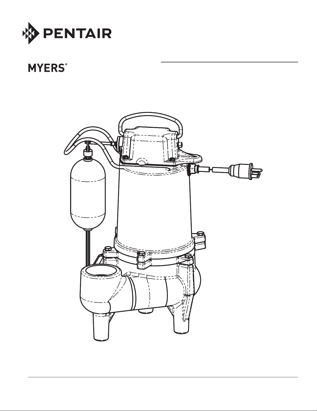
MSE50 Submersible Sewage
Ejec tor Pump
MODELS
MSE5012P10, MSE5012P20
MSE5022P10, MSE5022P20
NOTE! TO THE INSTALLER: Please make sure you provide this manual to the owner of the pumping equipment or to
the responsible party who maintains the system.
293 WRIGHT STREET, DELAVAN, WI 53115 WWW.FEMYERS.COM
PH: 888-987-8677 Fax: 800-426-9446
© 2018 Pentair plc. All Rights Reserved. MY1004 (Rev. 02/08/18)
490 PINEBUSH ROAD, UNIT 4, CAMBRIDGE, ONTARIO N1T 0A5
PH: 800-387-4386 ORDERS FAX: 888-606-5484

General
Information
Thank you for purchasing your
Myers® pump. To help ensure
years of trouble-free
op er a tion, please read the
fol low ing manual carefully.
Before Operation:
Read the following in structions care ful ly. Reasonable care
and safe meth ods should be
practiced. Check local codes and
requirements before installation.
Attention:
This manual contains
important information for the
safe use of this product. Read
this manual completely before
using this product and refer
to it often for con tin ued safe
product use.
DO NOT THROW AWAY OR
LOSE THIS MAN U AL. Keep it
in a safe place so that you may
refer to it often.
WARNING: Before handling
these pumps and controls,
always disconnect the power
first. Do not smoke or use
sparkable electrical devices
or flames in a septic
(gaseous) or possible septic
sump.
California Proposition 65
Warning
This product and
related accessories contain
chemicals known to the
State of California to cause
cancer, birth defects or other
reproductive harm.
Pump Warning
To reduce risk of electrical
shock:
1. Risk of Electrical Shock:
This pump has not been
in ves ti gat ed for use in
swimming pool areas.
2.Risk of Electrical Shock:
Connect only to a properly
ground ed receptacle.
Septic tank to be vented
in ac cor dance with local
plumbing codes.
Do not smoke or use
sparkable electrical
devices or flame in a septic
(gaseous) or possible septic
sump.
If a septic sump condition
exists and if entry into
sump is necessary, then
(1) provide proper safety
precautions per OSHA
re quire ments and (2) do not
enter sump until these
precautions are strictly
adhered to.
Do not install pump in
location clas si fied as
hazardous per N.E.C.,
ANSI/NFPA 70 - 2001.
Failure to heed above
cautions could result in
injury or death.
Pump Installation
These important instructions
must be followed for
satisfactory performance
of your pump. Before
installation, check your local
electrical and plumbing codes.
1. Provide proper sump size
to allow the pump to
operate without
restrictions. A two- to
five-minute run time is
recommended. Also,
minimum 24" diameter
recommended.
2. Make sure sump is free of
string, cloth, nails, gravel,
etc. before installing pump.
3. Do not set pump directly
on the bottom of sump pit
if it is not solid. Raise the
pump by placing bricks or
concrete blocks underneath
it.
4. Use steel or plastic pipe
for all connecting lines
between pump and sewer
outlet.
NOTE: Some city
regulations do not allow
installing a pump with
plastic pipe. Check local
regulations.
5. In applications where
the pump may sit idle for
months at a time, it is
recommended that the
pump(s) be cycled every
month to ensure the
pumping system is working
properly when needed.
6. A check valve should be
installed in discharge
pipe, at least 12" above
the discharge outlet of the
pump.
NOTE: If pumping raw
sewage, the check valve
must be installed in the
horizontal position
7. An audible alarm system,
for high water conditions
should be installed in
every pump for greater
protection.
8. Connect to power source
using 3-prong grounded
AC receptacle. Do not
remove ground pin from
electrical plug. Do not use
an extension cord.
9. Use pump partially or
completely submerged for
pumping (temperature to
140° F). The MSE50 will
pump solid materials up to
2" (spherical) in diameter.
CAUTION: Do not pump
flammable liquids, strong
chemicals or salt water.
2

Pump
Servicing
Servicing should be performed
only by knowledgeable pump
service contractors or
authorized service stations.
1. Remove pump from sump.
Before removing pump
from sump pit for repair,
check if the trouble could
simply be a blown fuse,
tripped circuit breaker, or a
power cord not completely
inserted into the receptacle.
2. Check switch.
3. Check for impeller blockage.
Disconnect pump from
power source. Check for an
obstruction in the impeller
cavity by laying the pump
on its side and inserting a
screwdriver into impeller.
Impeller should turn freely.
If impeller is stuck, then
turn the pump on its side,
DRAIN THE OIL through
the oil fill plug on top of
the pump. Drain oil into
a clean, dry container. A
milky appearance to the
oil indicates that water
has entered through either
worn out or damaged seals
(7) or seal ring. Remove the
3 screws (9) to remove the
volute (2). If the impeller (8)
does not rotate freely, clear
the impeller and cavity walls
before reassembling the
base. Repeat Step 2.
4. Check power cord. If the
above tests have not
resolved the problem, it
may be in the electrical
components of the pump.
Starting with the power
cord (19), inspect for cuts or
nicks in the insulation. If the
cord is damaged – replace
it!
5. Remove the motor cover.
Use a screw driver to
pry the motor cover (10)
from the seal plate (1) at
the fastening ears, being
careful not to cut the seal
ring with the screwdriver
or crack the motor cover.
Lift the motor cover until it
clears the stator (3).
6. Check for short. Disconnect
the stator leads from
the connector. Use an
ohmmeter to check the
continuity of the stator. If
stator fails to pass the
continuity test, it must
be replaced.
Ground check. Set
ohmmeter scale pointer to
R X 100K scale and check
meter by putting both
meter leads together and
adjusting the
needle knob until meter
reads zero. If meter cannot
be adjusted to zero it will
indicate that batteries in
meter must be replaced.
Always make this test
with the meter when scale
pointer is set to a new scale
before making any checks
on motor.
Now connect one meter
lead to one blade terminal
of stator and touch other
meter lead
to motor stator shell (3).
If needle reads below 5
(500,000 ohms) stator
must be dried out before
reusing. To dry out, bake
in 220° oven for 4 hours.
Recheck after motor
cools. If motor is new or
thoroughly dry, needle of
ohmmeter will not move
on the ground test. This
indicates a reading of 50
megohms or higher. One
megohm is one million
ohms.
When making the ground
test, if the needle goes
clear to zero the motor
probably has a wire
touching the stator at some
point and the stator will
have to be replaced.
7. Remove the stator. To
remove the stator, remove
the four hex head screws
(4) and disconnect the
capacitor leads from the
capacitor. Lift the stator off
the seal plate (1) and set
aside.
8. Remove the impeller. To
remove the impeller (8),
hold the rotor shaft (5)
with a screwdriver at the
center of the impeller and
tap the impeller with a
plastic or rubber mallet
so as to turn the impeller
counterclockwise.
9. Check the seal. Remove the
rotating portion of seal
(7) from shaft by inserting a
screwdriver under the edge
of the seal and lifting it off.
Inspect the seal face for any
nicks or an uneven seating
of seal face. If any are
present, replace the seal.
(See Step 14.)
Full Load Amps:
115 Volt ....................... 9 Amps
230 Volt .................... 4.6 Amps
10. Remove rotor. Tap the rotor
shaft (5) at the impeller
end of the shaft with a
plastic mallet to remove
the rotor and shaft. Inspect
the bearings. If they do not
rotate freely and smoothly,
they should be replaced.
3

11. Remove seal. Remove the
old stationary portion of the
seal (7) from the seal plate
by inserting a screwdriver
into the seal housing of the
seal plate from the top of
the case and tapping lightly
with a hammer. Clean the
seal area of the seal plate
(1) with a clean cloth.
12. Reinstall the rotor and shaft
assembly. Push on outer
face to seat bearing in seal
plate.
13. Reinstall seal. Apply a good
lubricant to the new
stationary portion of the
seal (7) and press into the
seal plate. Coat the new
rotating portion of seal with
lubricant and press into
place on the rotor shaft
with
the rubber ring facing
the impeller.
14. Reinstall impeller. Add a
drop of Loctite 222 to
the shaft and screw the
impeller on hand tight.
The impeller will force the
rotating portion of seal into
position.
15. Replace seal ring. Remove
the old square seal ring
from the seal plate and
stretch on a new ring
coated with O-ring lube.
Do not roll the ring onto
the seal plate or improper
seating and water leakage
into the motor housing will
result.
16.Reinstall the stator. Place
the stator (3) in the seal
plate (1) so the stator
bolt holes line up. Lay the
stator plate on the stator
(3) and line up with stator
bolt holes. Slide the ring
terminal of the ground
lead wire over one of the
stator bolts. Put in the
stator bolts and tighten
evenly to prevent cocking
of the stator. Connect the
capacitor to the capacitor
leads. Push the connectors
of the two black stator leads
onto the power cord pin
terminals. Push the ground
wire sleeve terminal over
the ground pin terminal.
(identified with the 'bump'
on the molded terminal
housing)
17. Reassemble pump. Replace
the motor cover (10) on
the seal plate (1). Place
the assembly on the volute
(2). Insert the three cap
screws (9) through the
motor housing ears, into
the tapped holes in the
volute. Tighten them evenly
to prevent cocking the
motor housing and causing
an uneven seal on the seal
ring.
18. Oil. Fill the motor cap with
high grade transformer oil
just covering over stator
end cap.
Do not fill the motor
housing
completely – allow airspace
for oil expansion. Make
sure the stator is fully
immersed. You will have
to peer through the oil
plug hole to be sure of the
correct oil level.
19. Reinstall oil pipe plug. Coat
pipe threads with thread
sealant before installing.
Plug into housing (14).
20. Check pump. Plug the
power cord into a grounded
outlet and start pump
by raising the switch rod
extending out of the switch
housing. Motor should run
smoothly, be free
of vibration and stop when
pressure is removed from
diaphragm switch.
21. Check for air lock. Myers
pumps have a small air
vent hole in the impeller
cavity to let out trapped
air. If this hole becomes
plugged, pump may air
lock. To break the air
lock, use a small
screwdriver to clear hole in
the
impeller cavity.
Switch
Replacement
As a secondary precaution
in installations of this type
— 1⁄16" hole should be
drilled in the discharge
pipe below the check valve.
The check valve should be
12 to 18 inches above pump
discharge. Do not put check
valve directly into pump
discharge opening.
NOTE: In basins where the
pump is operating daily,
air locking rarely occurs.
1. Disconnect power to the
pump.
2. Remove the pump from the
sump. Disinfect it for one
hour with chlorine bleach.
Wear rubber gloves when
handling the pump.
3. Remove the bottom tether
strap from the float rod, lift
the float and swing it
sideways, and remove it
from the switch arm.
4. Remove the four screws
that secure the switch
to the top of the motor
housing and lift the switch
off the motor. The switch
guard may come off with it.
44
5. Disconnect four wires that
222 0
connect the switch to the
motor housing.
6. Remove and discard the
gasket between the switch
and the pump. Clean the
gasket surface on the
motor housing.
7. Remove old switch and
replace.
8. Make sure the fork on the
rod fits over the switch
lever.
9. Set the new gasket on
the motor housing, then
connect the four wires on
the new switch to the four
terminals in the motor
housing
(see Figure)
10. With the switch guard in
place, set the switch on
the motor housing with
the switch arm pointed
toward the discharge side
of the pump and install and
tighten the four screws
which secure the switch to
the pump.
11. Holding the float out
sideways, hook the float
rod on to the switch arm
and swing the float rod
down.
12. Insert the float rod in the
hole in the tether strap.
13. Reinstall the pump in the
sump, check all piping
connections, and reconnect
the power. Run the pump
through one complete
operating cycle to check for
proper operation. Failure
to make this operational
check may lead to flooding
and will void the warranty.
NOTICE: When you connect
the two power wires to the
cord terminals, make sure
that the wire ends don’t
lodge between the cord pin
and the side of the cord
plug. The connector must
be on the pin.
7222 0717 7
717
55

MSE50 - Parts List
MSE5012P10 MSE5012P20 MSE5022P10 MSE5022P20
Ref. No. Description Quantity Part Number Part Number Part Number Part Number
1 SEAL PLATE 1.000 PW3-1421
2 VOLUTE,SEWAGE .2" DISCH 2" 1.000 21612D000
STATOR 4/10HP, 115V 1PH 1.000 26165B010
3
STATOR 4/10HP 230V 1PH 1.000 26165B011
4 SCREW-MACH(HEX HD)8-32X 3-3/16 4.000 001450101
5 ASSEMBLY ROTOR 1/2 HP 1.000 27479A001
6 BEARING-BALL 1.000 650241
7 1/2 SHAFT SEAL 1.000 21607A015
8 IMPELLER 1.000 21542B000
9 HEX CAP SCREW 6.000 19099A012
10 MOTOR COVER 1.000 PW18-1691
RUN CAPACITOR 15MFD 1.000 U17-1540
11
RUN CAPACITOR 4MFD 1.000 U17-2150
12 SCREW 1.000 U30-985SS
13 O-RING 1.000 U9-339
14 PLUG 1.000 U78-94SST
15 GREEN WIRE W/TERMINALS 1.000 PS17-2149
16 CORD CONNECTOR 2.000 PS17-1508
17 O-RING 2.000 U9-356
18 INSULATING DISK 1.000 PS18-82
CORD, POWER 10FT 115V 1.000 PW117-237-TSE
CORD, POWER 20FT 115V 1.000 PW117-122-TSE
19
CORD, POWER 10FT 230V 1.000 PW117-2126-TSE
CORD, POWER 20FT 230V 1.000 PW117-218-TSE
20* GASKET, SWITCH COVER 1.000 PS20-126
21* SWITCH COVER 1.000 PW70-85
22* MACH SCREW 4.000 U30-482SS
23* FLOAT SWITCH 1.000 PS17-1511
24* SCREW 8-32 X 5/8 HEX HD 2.000 U30-951PSW
25* FLOAT PIVOT ARM 1.000 PS41-5
26* E-RING, EXTERNAL 1.000 U9-472SS
27* VITON SHAFT BELLOWS SEAL 1.000 U9-483
28* RETAINING RING C-CLIP 1.000 U9-461
29* BELLOWS RETAINER 1.000 PW19-142
30* SCREW 2.000 U30-957SS
31* WIRE, GROUND (NOT SHOWN) 1.000 PS17-1509
32* WIRE, CORD ENTRY TO SWITCH (NOT SHOWN) 2.000 PS17-1510
33 FLOAT BODY 1.000 PS28-36P
34 RUBBER STANDOFF 1.000 PW19-141
35 FLOAT ROD 1.000 PW28-39
36 FLOAT ROD STOP 1.000 U9-463
37* PIPE PLUG 1.000 M15743
38 FLOAT PROTECTOR BRACKET 1.000 U97-194SS
39* HANDLE 1.000 U97-193SS
40 OIL (NOT SHOWN) 0.227 PO00VEL6
41 WASHER 1.000 U43-144SS
42 NYLON WASHER 1.000 U43-184
* SWITCH KIT 1.000 PW17-2130REP
66
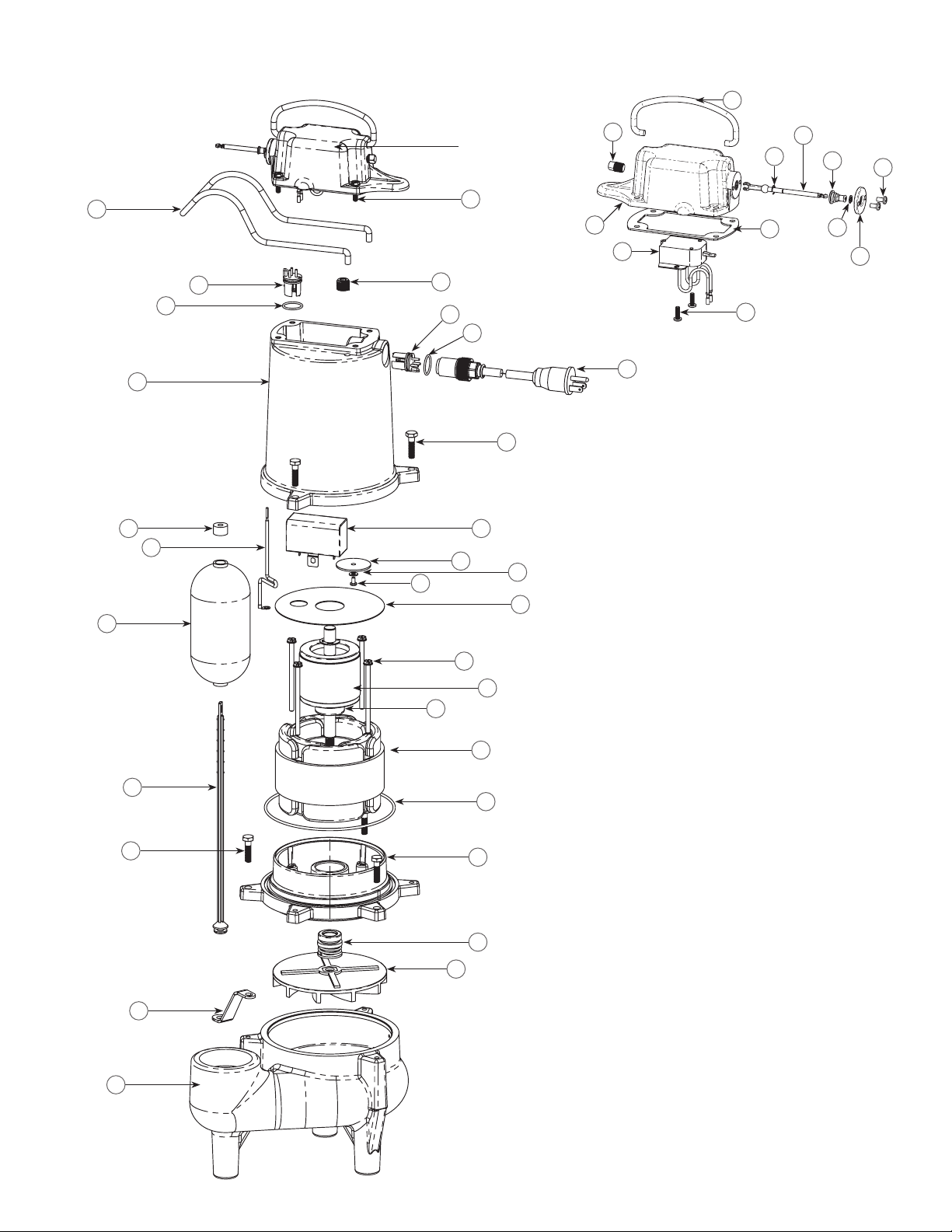
MODEL – MSE50
39
PW17-2130 REP
38
16
17
10
36
15
12
33
22
14
16
17
9
11
42
41
18
37
21
23
24
19
25
28
20
27
30
26
29
4
5
6
3
35
9
34
2
13
1
7
8
7

Limited Warranty
Myers® warrants to the original consumer purchaser (“Purchaser” or “You”) of the products listed below, that they will be free from
defects in material and workmanship for the Warranty Period shown below.
Product
Jet pumps, small centrifugal pumps, submersible pumps and
relatedaccessories
Fibrewound Tanks 5 years from date of original installation
Steel Pressure Tanks 5 years from date of original installation
Sump/Sewage/Effluent Products
Battery Backup Units
MBSP-2, MBSP-2C
MBSP-3, MBSP-3C
Wastewater Solids Handling Pumps
Our warranty applies only where such products are used in compliance with the requirements of the applicable product catalog
and/or manuals. For additional information, please refer to the applicable standard limited warranty featured in the product
manual.
Our warranty will not apply to any product that, in our sole judgement, has been subject to negligence, misapplication, improper
installation, or improper maintenance. Without limiting the foregoing, operating a three phase motor with single phase power
through a phase converter will void the warranty. Note also that three phase motors must be protected by three-leg, ambient
compensated, extra-quick trip overload relays of the recommended size or the warranty is void.
Your only remedy, and MYERS’s only duty, is that MYERS repair or replace defective products (at MYERS’s choice). You must pay
all labor and shipping charges associated with this warranty and must request warranty service through the installing dealer as
soon as a problem is discovered. No request for service will be accepted if received after the Warranty Period has expired. This
warranty is not transferable.
MYERS SHALL NOT BE LIABLE FOR ANY CONSEQUENTIAL, INCIDENTAL, OR CONTINGENT DAMAGES WHATSOEVER.
THE FOREGOING LIMITED WARRANTIES ARE EXCLUSIVE AND IN LIEU OF ALL OTHER EXPRESS AND IMPLIED WARRANTIES,
INCLUDING BUT NOT LIMITED TO IMPLIED WARRANTIES OF MERCHANTABILITY AND FITNESS FOR A PARTICULAR
PURPOSE. THE FOREGOING LIMITED WARRANTIES SHALL NOT EXTEND BEYOND THE DURATION PROVIDED HEREIN.
Some states do not allow the exclusion or limitation of incidental or consequential damages or limitations on the duration of an
implied warranty, so the above limitations or exclusions may not apply to You. This warranty gives You specific legal rights and You
may also have other rights which vary from state to state.
Warranty Period
whichever occurs first:
12 months from date of original installation,
or 18 months from date of manufacture
12 months from date of original installation,
or 36 months from date of manufacture
12 months from date of original installation,
or 18 months from date of manufacture
24 months from date of original installation,
or 30 months from date of manufacture
12 months from date of shipment from factory
or 18 months from date of manufacture
This Limited Warranty is effective April 1, 2014 and replaces all undated warranties and warranties dated before April 1, 2014.
F.E. MYERS
293 Wright Street, Delavan, WI 53115
Phone: 888-987-8677 • Fax: 800-426-9446 • www.femyers.com
In Canada: 490 Pinebush Road, Unit 4, Cambridge, Ontario N1T 0A5
Phone: 800-363-7867 • Fax: 888-606-5484
 Loading...