

Pentair MYERS MG200 Series Installation And Service Manual
MG200 SERIES
GRINDER PUMPS
INSTALLATION AND SERVICE MANUAL
2 HP Grinder Pump for Residential and Pressure Sewer Applications.
NOTE! To the installer: Please make sure you provide this manual to the owner of the equip ment or to the responsible
party who maintains the system.
Part # 23833A664 | © 2014 Pentair Ltd. | 07/16/14

USAGE
n CAUTION!
The MG200 Series is a submersible wastewater
grinder pump designed specifically for individual
residential and pressure sewer applications. The
pumps are to be used for domestic sewage only
and are not to be used for pumping commercial or
industrial sewage such as from motels, schools,
apartments, factories, etc. THIS PUMP IS NOT FOR
USE IN HAZARDOUS LOCATIONS!
INSPECTING PUMP
Before making any piping or electrical connections,
check the pump for shipping damage or cracks.
Using a flat screwdriver placed in the slot on the
shaft end, turn shaft and impellers to be sure they are
free. DO NOT TURN IMPELLER WITH FINGERS AS
EDGES ARE SHARP.
POWER SUPPLY
The MG200 Series grinder pump should be connected
only to a 230 volt, single phase, 60 Hz power source.
The pump will draw approximately 9.1 amperes at
minimum flow and 15.0 full load amperes. The pump
must be connected to a grounded power socket. DO
NOT cut off the ground pin from the power cord plug.
POWER CORD
A 20 foot power cord is attached to the grinder pump
via three insulated quick-disconnect terminals. To
replace a cord simply unscrew (turn counterclockwise)
cord nut from top of motor housing. Once cord nut
is completely loosened from housing, gently pull
cord upward away from housing. While cord is being
pulled, it may be necessary to shift cord leads back
and forth to guide the insulated terminals through
the hole in the motor housing. Once the terminals
have cleared the hole, gently pull cord until terminals
are completely outside motor housing. Then simply
disconnect terminals to remove cord.
To install new cord, reconnect terminals (black to
black, white to white, green to green), and guide
terminals back through hole in motor housing. Once
terminals have passed through the hole, retighten the
cord nut into housing. Tighten nut firmly but do
not overtighten.
The power cord should be replaced if it has
been damaged in any way or the cord jacket
has become brittle.
MOTOR TYPE
The MG200 Series grinder pump contains a 3/4
frame, 2 HP, single phase, 60 Hz, 3450 RPM, capacitor
start, capacitor run motor with Class F insulation and
built-in, on-winding overload protection. Motor has
upper and lower ball bearings and is oil-cooled
and lubricated.
THE MG200 SERIES GRINDER PUMP SHOULD
NEVER BE WORKED ON WITHOUT FIRST
DISCONNECTING THE POWER CORD.
OIL TYPE
The motor housing contains dielectric transformer oil
to provide good heat transfer and lubrication of ball
bearings; no other lubrication is required. Oil level
may be checked by removing the nut and washers
from the top of the motor housing. The oil level
should be filled to the bottom of the end shield. Do
not overfill with oil. Only dielectric transformer oil
obtained from a Myers
should be used.
®
authorized service center
PUMP SWITCH INSTALLATION
INSTRUCTIONS
NOTE: In accordance with third party approval, pump
must be submerged a minimum of 8-1/2" from bottom
of the legs on volute case during operation.
Mounting the Switch
1. Determine pumping range for installation. Do not
tether less than 3-1/2" from pipe.
2. Tighten strap around discharge pipe keeping
switch cable between strap and pipe to prevent
slippage.
3. Space small ties at least 1" apart. To readjust ties,
press small tie tabs down.
4. To lock releasable tab, run remaining
strap between tab and head. Tuck strap back
through head.
Piggyback Plug Install
n
Electrical outlet must not be located
in pump chamber.
n Electrical outlet voltage, piggyback plug voltage,
and pump voltage must match.
1. Follow steps 1 through 4 of “Mounting the Switch.”
2. Insert switch’s piggyback plug into outlet.
3. Plug pump into piggyback plug.
4. Check installation. Allow system to cycle to ensure
proper operation.
Direct Wire Install
1. Follow steps 1 through 4 of “Mounting the Switch.”
2. Further wiring of switch should be done by
qualified professionals only.
3. Check installation. Allow system to cycle to ensure
proper operation.
2
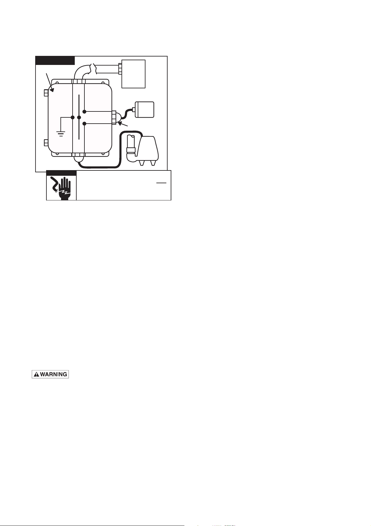
230 VAC
junction
box
REPLACING GRINDER IMPELLER AND
230V
power
source
G
L1
L2
GRINDER SHREDDING RING
All repairs must be done at the factory or at an
authorized Myers
®
service facility.
black
G
n WARNING
white
G
L1
L2
In 230 VAC pump installations, one side of
the line going to the pump is always HOT.
This condition exists if the switch is on or
off. Install double pole disconnect on all
230 VAC pump circuits.
liquid-tight
connector
230V
pump
SAFETY WARNINGS
n WARNING! Risk of electrical shock. Pumps are
supplied with a grounding conductor and groundingtype attachment plug on the power cord (except
MG200-21L/P). To reduce the risk of electrical
shock, be certain that it is connected only to properly
grounded, grounding-type receptacle. DO NOT cut
off ground pin or use an adapter fitting. DO NOT
use an extension cord with this pump. When wiring
this pump follow all local electrical, safety codes and
ordinances as well as most recent National Electric
Code (NEC-ANSI/NFPA).
The MG200 Series grinder pumps have a GROUND
WIRE that is connected to a screw in the metal motor
housing. This wire goes to the receptacle or control
box which must be connected to a good outside
GROUND such as a metal water pipe or GROUND
STAKE driven at least 8 feet into the ground.
CALIFORNIA PROPOSITION 65 WARNING:
This product and related
accessories contain chemicals known to the
State of California to cause cancer, birth
defects or other reproductive harm.
DISMANTLING PUMP FOR
REPLACEMENT PARTS
Before dismantling pump for replacement parts, clean
pump thoroughly.
n CAUTION!
DISCONNECT ALL POWER AND CONTROL
WIRES TO MOTOR AT CONTROL PANEL BEFORE
STARTING DISASSEMBLY OPERATIONS. NEVER
RELY ON OPENING CIRCUIT BREAKER ONLY.
DISASSEMBLY OF SHREDDING RING
AND GRINDER IMPELLER
1. Remove three screws from grinder ring flange.
Grinder ring is pressed into flange for easy
removal.
2. Using Allen head socket wrench, thread two
screws into tapped back-off holes in flange. Evenly
tighten screws to guide grinding ring out of pump
volute case.
3. Hold grinder impeller by prying against impeller
cutting bar and remove cap screw from end
of shaft.
4. Use large screwdriver in slot in end of shaft
and bump on cutter vane with plastic hammer.
Bump in counterclockwise direction as thread
is right-hand. It may take several bumps to
loosen impeller.
DO NOT CONTINUE TO POUND ON IMPELLER
AS IMPELLER AND SHAFT MAY BE DAMAGED.
5. If impeller comes off easily, clean and replace
if worn.
6. Be sure pump impeller has not loosened when
grinder impeller is removed. This can be checked
on reassembly of grinder impeller and shredding
ring. Tips of impeller cutter vanes should extend
about 1/8" below bottom of shredding ring. If
distance is more, it means the pump impeller has
loosened, and if it is less, it means the shredding
ring is not properly seated.
If the pump impeller has loosened, remove grinder
impeller and shredding ring as described above
and remove bolts from volute case and remove
case. Plastic hammer can be used to bump on
casing discharge to loosen. Place gasket in oil
to prevent drying out. DO NOT loosen the pump
impeller further – it is the seat for the seal spring.
7. After case is removed, wrap emery paper around
shaft and hold with vice grip pliers. Use cloth
on impeller and screw up against shoulder. Now
pump can be reassembled.
8. Clean all threads with wire brush and file; smooth
any threads that may have been nicked.
3
 Loading...