

Pentair Myers MES100, Myers MES50 Installation And Operator's Manual
INSTALLATION AND
OPERATOR'S MANUAL
Submersible Sewage
Ejector Pump
INSTALLATION ET MANUEL
DE L'OPÉRATEUR
Pompe submersible
d'eauxd'egout
Installation/Operation/Parts
For further operating, installation, or
maintenance assistance:
Call 1-888-987-8677
English ..........Pages 2-12
293 WRIGHT STREET, DELAVAN, WI 53115 WWW.FEMYERS.COM
PH: 888-987-8677 ORDERS FAX: 800-426-9446
490 PINEBUSH ROAD, UNIT 4, CAMBRIDGE, ONTARIO, N1T 0A5
PH: 800-363-7867 ORDERS FAX: 888-606-5484
© 2016 Pentair plc. All Rights Reserved. 23833A704 (05/25/16)
MES50/MES100
Installation/Fonctionnement/Pièces
Pour plus de renseignements concernant
l’utilisation, l’installation oul’entretien,
Composer le 1 (888) 987-8677
Français ........Pages 13-24
Safety 2
Contents
Important Safety Instructions .......................2
Installation .......................................3
Operation ........................................5
Maintenance ......................................5
Ground check .................................... 6
Reassembly ...................................... 7
Oil fill ........................................... 7
Troubleshooting ..................................8
Repair Parts ......................................9
Warranty .......................................11
Product Specifications ............................12
Important Safety Instructions
SAVE THESE INSTRUCTIONS - This manual contains
important instructions that should be followed during
installation, operation, and maintenance of the product.
Save this manual for future reference.
This is the safety alert symbol. When you see this
symbol on your pump or in this manual, look for one of
the following signal words and be alert to the potential
for personal injury!
indicates a hazard which, if not avoided, will
result in death or serious injury.
indicates a hazard which, if not avoided,
could result in death or serious injury.
indicates a hazard which, if not avoided,
could result in minor or moderate injury.
NOTICE
The manufacturer cannot anticipate every possible
circumstance that might involve a hazard. The warnings
in this manual, and the tags and decals affixed to the unit
are, therefore, not all-inclusive. If you use a procedure
or operating technique that the manufacturer does not
specifically recommend, you must satisfy yourself that it
is safe for you and others. You must also make sure that
the procedure or operating technique that you choose
does not render the system unsafe.
addresses practices not related to personal injury.
Electrically powered sewage pumps normally give many
years of trouble-free service when correctly installed,
maintained, and used. However, unusual circumstances
(interruption of power to the pump, large solids in
the sump, flooding that exceeds the pump’s capacity,
electrical or mechanical failure in the pump, etc.) may
prevent your pump from functioning normally. To prevent
possible damage, consult your dealer about installing
a secondary sewage pump or a high water alarm. See
Troubleshooting in this manual for information about
common sewage pump problems and remedies. For
more information, see your retailer, call Hydromatic
customer service at 1-888-957-8677 or visit our web site
at hydromatic.com.
Hazardous voltage - risk of electrical
shock. Shock can cause serious injury or death.
Failure to follow the warnings below can result in fatal
electricshock.
Burn Hazard.
high temperatures. Do not touch an operating motor. To do
so can cause personal injury.
Risk of flooding. If a flexible discharge hose
is used, pump may move around in sump when motor
starts. If it moves far enough so that the switch hits the
side of sump, the switch may stick and prevent the pump
from starting. Make sure the pump is secured so it cannot
move around in the sump.
Modern motors can operate at
Safety • Installation 3
Hazardous pressure and gas - risk of
explosion and personal injury. Failure to follow the
warnings that follow can result in personal injury.
1. If your basement has water or moisture on the floor,
do not walk on the wet area until all the power
has been turned off. If the shut-off box is in the
basement, call the electric company or the hydro
authority to shut off the service to the house, or call
your local fire department for instructions. Do not
handle the pump or pump motor with wet hands or
when standing on wet or damp surfaces.
2. Connect only to a properly grounded receptacle.
3. All wiring should be performed by a
qualifiedelectrician.
4. Protect the electrical cord from sharp objects, hot
surfaces, oils, and chemicals. Observe the Cord Lift
Warning shown below.
5. Risk of explosion and hazardous gas. Septic
tank must be vented in accordance with local
plumbingcodes.
Do not smoke or use sparkable electrical devices or
flame in a septic (gaseous) or possible septicsump.
If a septic sump condition exists and if entry into
sump is necessary, then (1) provide proper safety
precautions per OSHA requirements and (2) do
not enter sump until these precautions are strictly
adhered to.
Do not install pump in location classified as
hazardous per N.E.C., ANSI/NFPA 70- 2001.
6. Know the pump application, limitations and
potential hazards.
7. Wear safety glasses at all times when working with
the pump.
Keep the work area clean, uncluttered and properly
8.
lighted - secure all unused tools and equipment.
9. Keep visitors at a safe distance from working area.
10. Make the workshop child-proof - with padlocks,
master switches, and by removing starter keys.
11. Release all pressure within the system before
servicing any component.
12.
Provide a means of pressure relief for pumps whose
discharge line can be shut-off or obstructed.
13. Periodically inspect the pump and system
components. Perform routine maintenance
asrequired.
14. Drain all the liquid from the system beforeservicing.
California Proposition 65 Warning
This product and related accessories contain
chemicals known to the State of California to cause
cancer, birth defects or other reproductive harm.
Installation
Thank you for purchasing this Hydromatic® pump. To
help ensure years of trouble-free operation, please read
the manual carefully.
Before installation, check your local electrical and
plumbing codes. Typical sewage pump installations are
shown on the next page.
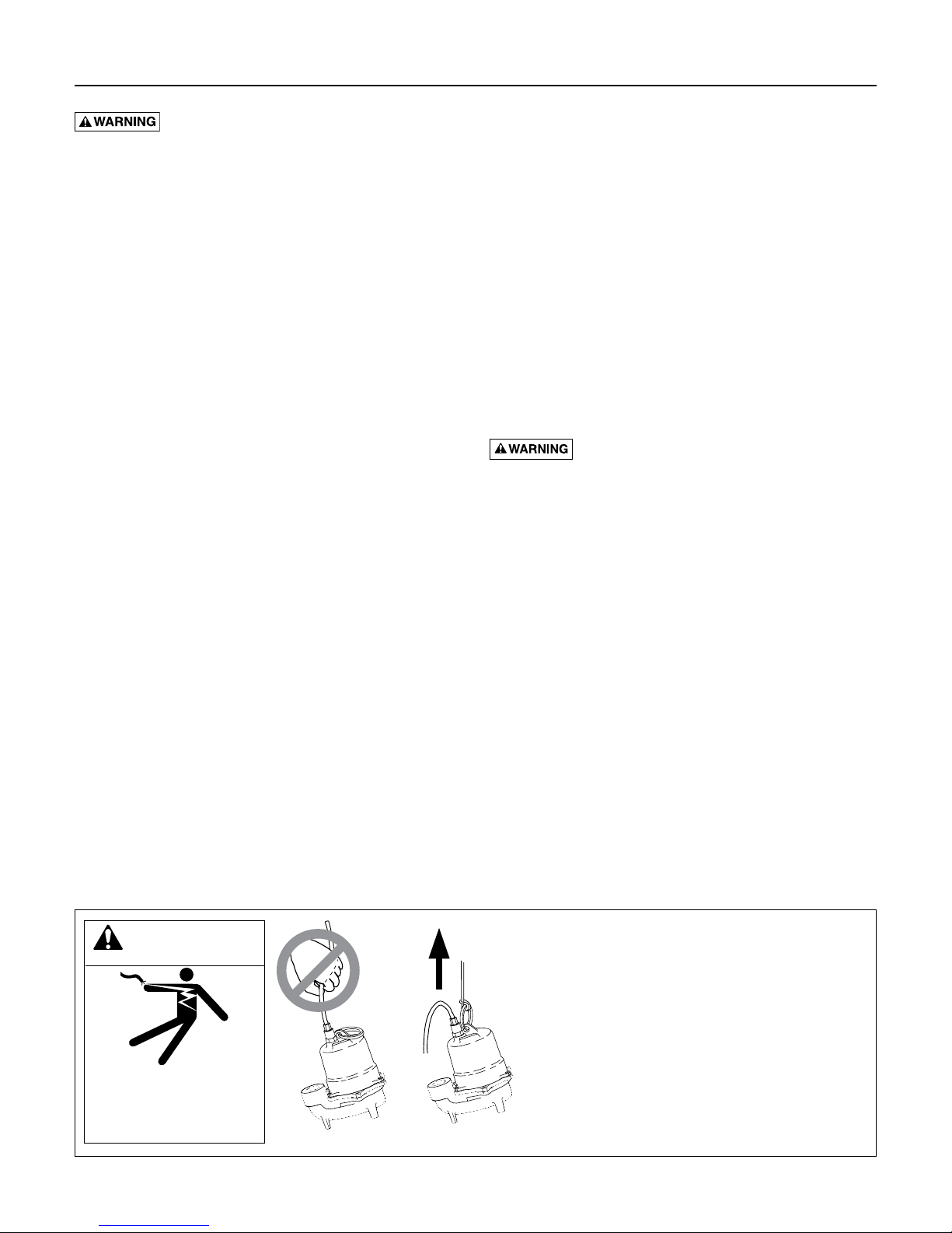
WARNING
Risk of electrical shock.
Can burn or kill.
Do not lift pump by
powercord.
Cord Lift Warning
Risk of electrical shock and fire.
1. Attempting to lift or support the pump by
the power cord can damage cord and cord
connections, expose bare wires, and cause
a fire or electrical shock.
2. Use handle on top of pump for all lifting or
lowering of pump. Disconnect the power
to the pump before doing any work on it
or attempting to remove it from the pit.
3. Lifting or supporting the pump by the
power cord will void the warranty.

Installation 4
Typical Single Phase Switch Operated Installation
Typical Three Phase Simplex Installation with float

Installation • Operation • Maintenance 5
Follow these guidelines for installation:
1. Provide properly sized pit (see Specifications) on
sewage tank. Minimum pump run time is two
minutes. For maximum pump life, three minutes
isrecommended.
2. Make sure sump is free of string, cloth, nails, gravel,
etc., before installing pump.
3. Do not set pump directly on the bottom of sump pit
if it is not solid. Raise the pump by using bricks or
concrete blocks underneath it.
4. Do not remove ground pin from electrical plug.
5. Do not use an extension cord to operate thispump.
6. For proper automatic operation, make sure the pump
power cord is plugged into the piggyback receptacle
on the switch cord. Three phase models must be
properly connected to a suitable controlpanel.
Do not cut, crimp, or bend single phase switch
power cord. This may cause pump failure and
voidwarranty.
7. Use steel or plastic pipe for all connecting lines
between pump and sewer outlet.
NOTICE: Some city regulations do not
allow installing a pump with plastic pipe.
Checklocalregulations.
8. Use PTFE pipe thread sealant tape on pipe
connections. Do not use ordinary pipe joint
compound on plastic pipe or pump. Pipe joint
compound can attack plastics and damage pump.
9. In applications where the pump may sit idle for
months at a time, it is recommended that the
pump(s) be cycled every month to ensure the
pumping system is working properly whenneeded.
10. A check valve should be installed horizontally in the
discharge pipe.
11. The optional Hydromatic Q Alert is an audible
alarm system for high water conditions. It should be
installed in every sump for greater protection.
NOTICE: Q Alert is for indoor use only. Other
Q Alarm and control panels are available for
outdoor use. Contact your Hydromatic distributor
forapplications.
12. Use pump partially or completely submerged for
pumping waterlike liquids. The pump will pump
solid materials up to 3/4” (spherical) in diameter.
liquids. Strong chemicals or salt water should not
be pumped without consulting your Hydromatic
distributor for proper seals and coatings.
Risk of fire. Do not pump flammable
Operation
NOTICE: Do not allow pump to run in a dry sump.
Doing so will void the warranty and may damage
thepump.
An automatic overload protector in the motor will
protect the motor from burning out due to overheating/
overloading. When the motor cools down, the overload
protector will automatically reset.
If overload trips frequently, check for the cause. It could
be a stuck impeller, wrong/low voltage, or electrical
failure in motor. If an electrical failure in the motor is
suspected, have it serviced by a competent repairman.
Maintenance
Read the following instructions carefully before replacing
any parts. Reasonable care and safe methods should be
practiced. Check local codes and requirements before
installation. Only a competent plumber/electrician
should make the installations.
Submerge pump in a disinfectant solution (dilute chlorine
bleach) for at least one hour before disassembling pump.
The following steps should be performed only by an
authorized service center.
NOTICE: Read all directions before replacing any
parts. Remove pump and switch from power source
beforeservicing.
The numbers in parentheses, such as "(3)" or "(16)", refer
to item numbers used on the Repair Parts diagram.
Checking power cord
To be sure wires are not burned off or broken in cord,
use ohmmeter for check. Set ohmmeter scale to RX1
scale and check meter by putting both meter leads
together and adjusting the needle knob until meter reads
zero. If meter cannot be adjusted to zero, the batteries in
meter must be replaced.
NOTICE: Always reset meter to zero [0] when going to a
new scale before making any checks on motor.
Attach one meter lead to white cord wire and one meter
lead to black cord wire, then place a screwdriver blade
across terminals of plug. If cord is OK, meter needle
will go to zero and stay there. If meter needle does not
move, the cord has an open wire and the cord must
bereplaced.

Maintenance 6
Checking motor operation
If the unit is being operated by float switch, unplug
the pump from the piggyback receptacle and plug the
pump directly into the power source. Motor should start
and run smoothly. If motor does not start each time it is
plugged directly into the receptacle and does not start
each time when plugged into the piggyback switch with
the float raised, replace the complete piggyback switch
assembly and retest with new assembly.
If motor does not run when tested with functional switch,
the capacitor and/or stator must be checked.
Checking motor stator
1. Remove plug (6) from top of housing (2) and pour
oil into a clean glass container. If oil is clear, it
will indicate motor is not burned and there has
been no water leak into the motor. If oil is black,
it will indicate a burned stator. If oil is cloudy, it
will indicate water in motor oil, so all seals should
bereplaced.
2. After draining oil, carefully loosen the power cord
assembly (22) from the motor housing (2). With
power cord loose, remove the screws (4) and
carefully lift off the motor housing (2) exposing the
motor assembly.
3. On single phase (1ø) units, check capacitor (28)
using ohmmeter. With ohmmeter scale set at
Rx1000, attach meter leads to capacitor leads.
The meter needle should go to zero and come
back slowly. If it does not, the capacitor should
bereplaced.
4. To check motor stator, remove power cord leads
from terminals on top of motor (1ø) or remove
splice connectors (3ø). If stator is visibly burned,
motor assembly must be replaced. If stator is not
burned but the oil shows signs of water, stator can be
checked with the ohmmeter to see if it can be used.
Ground check
Set ohmmeter scale to R X 100K scale. Connect one
meter lead to one blade terminal of stator and touch
other meter lead to motor housing (2). If the resistance
to the ground is less than 500,000 ohms, stator must be
dried out before retesting. To dry out, place pump in 220
degree oven for four hours. Recheck after motor cools.
If motor is thoroughly dry, needle of ohmmeter will not
move on the ground check. This indicates a reading of
50 megohms or higher. When making the ground check,
if the needle goes to zero, the motor has a wire touching
the stator shell at some place and the stator will have to
be replaced. Repeat for each leg or wire lead.
NOTICE: If motor shows a satisfactory ground check then
the winding resistance must be checked.
Winding resistance test
1. Use ohmmeter with scale set to RX1 scale. On this
scale, meter reads directly in ohms. Recheck to zero
[0] before making a reading on thewinding.
NOTICE: If water is found in motor, seal should
bereplaced.
2. For single phase pumps, connect one meter lead to
the white wire terminal and the other meter lead to
the black wire terminal. This reading is for the main
winding. If the readings obtained do not agree with
those given below, the stator is defective and the
motor assembly must bereplaced.
Reconnect the wires as they were removed.
Replacing seal
A milky appearance to the oil collected earlier indicates
that water has entered through worn or damaged seals
or O-rings. In this case, the mechanical seal (14) and
the O-ring (19) will have to be replaced. The seal (14)
consists of a ceramic stationary seat and a carbon
rotating ring. To check seal:
1. Remove bottom plate (12) and impeller (11).
2. Remove the rotating carbon ring and stainless
steelspring.
3. Remove the hex head stator bolts and lift the stator
(3). A screwdriver can be inserted under the stator
shell in order to remove the stator.
4. Tap the end of the shaft with a plastic or rubber
hammer. This will push the rotating half of the
mechanical seal from the shaft and also push the
lower bearing from the seal plate. Now remove
the shaft, rotor, and bearing assembly from the
sealplate.
5. Turn the bearing by hand: if it feels rough when
turned or looks rusted, it should be replaced. Use a
bearing puller to remove the bearing.

Maintenance 7
Reassembly
1. Thoroughly clean the seal (14) and bearing pockets
in the volute. All sand and dirt must beremoved.
2. If the stationary seal half was removed, use a plastic
pusher to press it into the housing. Make sure the
rubber ring goes in first. Do not use any sharp
objects that may damage the seal.
3. When installing a replacement bearing, press only
on the inner face and make sure the bearing is flush
against the snap ring. If a press is not available, the
bearing can be tapped onto the shaft using a sleeve
that bears only on the inner face. Pressing on the
outer face will ruin the bearing.
4. Push the shaft, rotor and ball bearing assembly into
the seal plate, being careful not to chip the ceramic
of the stationary seal half.
5. Replace wavy washer.
6. Replace the motor if it is visibly burned or if the
ground resistance test or the winding resistance test
has failed. Note that the replacement stator must be
of the same manufacture as the existing rotor, or vice
versa. Replace the four stator bolts.
7. Remove the old O-ring (19), regardless of condition,
and replace. Place the new O-ring over the seal plate
shoulder. Do not “roll” it. If twisted, water may enter
chamber and cause failure.
8. Reattach power wires and ground.
9. Clean the motor housing (2) thoroughly, then
position it onto the seal plate.
10. Press the new ceramic seal (14) in place with
the rubber ring facing the impeller. This should
have a thin oil (dielectric, same as in motor
housing)coating.
NOTICE: Ceramic must be kept clean. Any dirt
will cause seal failure. Also, mixing old and new
seal parts will cause immediate seal failure. When
replacing seal, replace both the rotating and the
stationary seal halves.
11. Reassemble the lower seal as described.
12. Add a drop of 2Loctite® #243 to the impeller threads
and screw the impeller hand tight. The impeller will
force the ceramic seal into position. The shaft should
be free of dirt, grease, etc., or the Loctite® will not
hold as designed. Replace impeller washer and
impeller screw to the shaft on three phase models.
2
Henkel Corporation, Germany
NOTICE: Loctite® overrun onto the seal or bearing
will result in shaft seizure.
13. Install bottom plate (12) and gasket (15).
14. To replace the power cord (22) on single phase
pumps, first slip the stator lead wires through the
holes in the wire seal assembly. Coat the cord grip
threads with PTFE pipe thread sealant tape and
screw the new power cord assembly into the motor
housing. Referring to wiring diagrams in this manual,
secure wires together with wire nuts.
NOTICE Do not tape leads together as the hot oil
will deteriorate the tape and cause failure.
15. Before filling the motor housing with oil, a seal leak
test should be performed. Apply 7 to 8 pounds of
air pressure in the 1/4" NPT tap (6) on the top of the
motor cover and seal chamber.
NOTICE Too much pressure will damage the seal.
Seal would have to be replaced.
Then submerge the pump in water and check for
leaks. If a leak occurs, isolate where it is coming
from and correct the problem by replacing the
failedpart.
Hydromatic pumps have a small air vent hole in
the impeller cavity to let out trapped air. If this hole
becomes plugged, pump may air lock. To break the
air lock, use a small screwdriver to clear hole in the
impeller cavity.
As a secondary precaution in installations of this
type, an 1⁄8” hole should be drilled in the discharge
pipe just above the volute. The check valve should
be at least 12 inches above pump discharge and
mounted horizontally. Do not put check valve
directly into pump discharge opening.
NOTICE: In sumps where the pump is operating
daily, air locking rarely occurs.
Oil fill
1. After seal leak test is satisfactory, remove unit from
water and wipe or blow off any excess water.
2. Do not put oil in motor with any water present in
motor cavity.
3. Use refined paraffinic transformer oil, 3Shellflex™
2210 or equivalent.
3
Shell Oil Company, Texas
4. Slowly fill oil to 1/8" over windings in motor housing
through opening (6). Use an oil fill tube that will go
into holes so that air can escape. Replace plug (6).
NOTICE Do not fill the motor housing completely –
allow air space for expansion.
5. Connect power cord wires to terminals in panel, or
connect power source, and check pump running.
Motor should run smoothly and be free of vibration.
Pump is ready for operation.

Troubleshooting 8
Troubleshooting
kill. Disconnect power before attempting any service or
repair work on pump.
Symptom Possible Cause(s) Corrective Action
Motor not running
Pump runs continuously
Little or no effluent
delivered from pump
Pump cycles constantly
Hazardous voltage. Can shock, burn, or
Motor protector tripped.
Open circuit breaker or blown fuse.
Impeller clogged or binding.
Power cable damaged.
Bad control panel. Inspect control panel wiring. Call a licensed electrician.
Defective liquid level switch.
Not enough liquid in wet well to activate
controls.
Liquid level cords tangled Untangle cords for free operation.
Automatic controls defective Try running pump in manual mode. If it runs, the automatic control is at fault.
Liquid level control cords tangled Untangle cords for free operation.
Pump is airlocked.
Flow in matches or exceeds the pump’s
capacity.
Check valve plugged, stuck shut, or
installed backwards.
System head excessive. Consult dealer.
Pump suction plugged. DISCONNECT POWER, pull pump, inspect, and clear as needed.
Wrong voltage or not wired correctly.
Pump is air locked.
Worn or damaged impeller. DISCONNECT POWER, pull pump and inspect impeller. Replace if necessary.
Liquid level controls incorrectly installed
or defective.
No discharge check valve installed. Install discharge check valve.
Discharge check valve stuck open. Repair or replace check valve as necessary.
Sewage wetwell too small. Consult dealer.
Liquid level controls incorrectly installed
or defective.
Pump too small for inlet flow. Consult dealer about larger pump or second pump.
which can cause loss of fingers. Keep hands away from
pump suction inlet when working on or servicing pump.
Allow motor to cool. Make sure pump is completely submerged. Clear debris from volute
and impeller. Check for high amp draw.
Replace fuse or reset breaker. If circuit breaker opens repeatedly, don’t reset it - call a
licensed electrician.
Check amp draw. If it is more than twice the nameplate amps, the impeller is locked.
Bearings and shaft may be damaged. DISCONNECT POWER, clear debris from volute,
impeller, and cutter as needed.
Resistance between power cable and ground should be infinity. If any reading is less than
infinity, call a licensed electrician.
With switch disconnected from power, check continuity through switch while activating
liquid level switch. Replace switch if necessary.
Allow the liquid to rise several inches above the switch-on level.
Stop pump for about one minute, then restart. Repeat stopping and starting until the
airlock clears. If the airlock persists, DISCONNECT POWER, pull the pump and drill a
1/8” hole in the discharge pipe between the pump discharge and the check valve.
A larger pump or more pumps may be needed.
Make sure check valve is installed correctly (flow arrow should point away from pump)
and functioning correctly.
Check pump’s rotation; check nameplate voltage against supply voltage (they must
match); consult a licensed electrician.
Stop pump for about one minute, then restart. Repeat stopping and starting until the
airlock clears. If the airlock persists, DISCONNECT POWER, pull the pump and drill a
1/8” hole in the discharge pipe between the pump discharge and the check valve.
Reposition or replace as necessary.
Reposition or replace as necessary.
Hazardous impellers and unexpected starts
 Loading...