

Pentair Myers HPL Series, Myers HPLT Series Installation And Service Manual
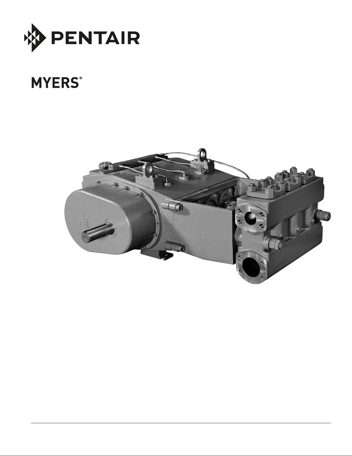
HPL/HPLT SERIES
HIGH PRESSURE
RECIPROCATING PUMP
INSTALLATION AND SERVICE MANUAL
NOTE! To the installer: Please make sure you provide this manual to the owner of the equip ment or to the responsible
party who maintains the system.
Part #23833A169 | © 2017 Pentair plc | 07/26/17

GENERAL INSTRUCTIONS:
Electrical power or engine must be shut off completely
before attempting service on the pump or its
drive. Air surrounding the unit is to be free of toxic,
flammable, or explosive gases.
A properly placed and sized relief valve installed in the
pump discharge system is necessary for protection
and to avoid dangerous overpressure. The relief valve
set pressure should not be more than 25% above
the design operating pressure and should discharge
to the tank or to the atmosphere toward the ground.
It must not be directed back to the pump suction
system.
CAUTION: All pumps should be installed level. For
mobile applications the maximum angle of intermittent
operation should be no more than 5° in any one
direction. Improper installation or use could result in
loss of life.
CALIFORNIA PROPOSITION 65 WARNING:
contain chemicals known to the State of California to
cause cancer, birth defects or other reproductive harm.
This product and related accessories
discharge line to the atmosphere at the lowest point
in discharge piping. If there are several low points
in the discharge line, drain individually. Drain the
bypass line by disconnecting or removing plug. If
pump has valve lifters, turn hand wheel to unseat
valves to prevent frost. If no valve lifters are present,
open piping lines to the atmosphere and run pump
15 seconds. Make sure pump does not run longer as
this can ruin the packing.
SERVICE:
Lubrication: Fill the crankcase with synthetic
80W140 gear oil with API classification GL-5 (SAE
J2360). When first operating the pump, change the
oil and filters after the first 30 hours of run time,
then every 300 hours or once a year. Maintain oil
level at the half way point on the oil level sight glass,
approximately 8.5 gallons. Check oil level daily and
add oil as needed. Use spin-on water-absorbing
filter; WATERGUARD® and inline oil filter; FLOW EZY
FILTERS® replacement element.
GUIDED VALVES WITH URETHANE/
*FLUORELASTOMER SEAL:
* Seal for HPLT Pumps
STARTING THE PUMP:
Fill pump crankcase with recommended oil to the half
way point on the oil level sight glass, approximately
8.5 gallons. Replace all drain plugs in the pump and
piping. Inspect tank to be sure that no foreign material
is in the tank or suction line. Fill tank at least half
full. Avoid prolonged dry operation which may cause
excessive wear on plunger packing. Be sure that an
operating pressure gauge is located in the discharge
line. Use a heavy duty, liquid filled, pulsation free
pressure gauge. Make sure all valves, including the
spray gun or nozzles, are open in discharge line and
completely back off pressure adjusting device on
pressure regulating valves. Check pressure rating
for pulsation dampener pressure regulator and pipe
fitting to make sure working pressure is not over the
maximum pressure rating.
After starting, close the discharge valve or spray gun
slowly while watching pressure gauge to make sure
relief valve or unloader is operating properly. Adjust
relief valve or unloader to desired pressure. Cycle
nozzles, or gun, on and off to be sure that pressure
adjustment and regulator operation is satisfactory.
Nozzle capacity should not exceed 90% of pump
capacity for satisfactory regulator operation. Avoid
freezing by draining all water from the pump and
system in cold weather.
INSTRUCTIONS FOR DRAINING PUMP IN
FREEZING WEATHER:
Open suction line to the atmosphere at lowest point
in suction piping and remove suction pipe plug. Open
These valves permit quick, easy and safe methods
of installing and removing the whole valve. The new
system allows servicing without distortion of the
seat, no damage to the fluid end and no special tools
are needed. Guided valves do not have any tapered
seats so the installation and removal of the valves are
extremely less complicated and destructive to the
fluid end.
The valves are made to sit on top of one another and
work together, therefore, there are no threads for
the valves to screw into. The use of a puller might
be needed.
Before installing, thoroughly clean all surfaces using a
cleaning solvent.
Installation will be through the top of the fluid end.
For the suction valve, drop down these parts in the
following order; O-ring, valve casting/cage, valve,
spring and then washer.
Repeat this same process for the discharge valve. To
complete, the washer that is on top of the discharge
valve needs to be placed concave side down. Slide
the valve cover over the four designated studs and
tighten the bolts.
BEARING HALVES/CONNECTING
RODS/CROSSHEADS:
The connecting rod assemblies employ precision
automotive type steel, backed with Babbitt-lined
crankpin bearing halves, which require no shims for
2

clearance adjustment. This pump employs full circle
crossheads and hardened stainless steel extension
rods, which are field replaceable.
Extension rods are provided with wrenching flats
to permit tightening of the tapered thread into the
crosshead, establishing accurate alignment.
Before beginning the assembly, all parts must be
cleaned, removing all oil, dirt, rust and foreign matter
which prevent proper fitting or scoring of the rubbing
surfaces. Clean and examine the power frame bores
for scoring and normal wear, especially the lower
crosshead guide way.
Check that all oil holes are clean and fully open. All
surfaces must be perfectly clean and lightly oiled
prior to assembly. Remove any burrs or sharp corners
which may prevent the fitting of bearings.
HPL pumps utilize high strength cap bolts suitable for
initial loadings, maintained by hardened spring lock
washers. After all rods and caps are secured, slowly
turn the crankshaft to be sure bearings do not bind.
Examine the location of each connecting rod within its
crosshead to verify it does not touch the crosshead
boss or skirt.
Frame bores which have become worn must be
sleeved with a cast iron liner to re-establish correct
geometry and alignment.
Installing Wrist Pin Bushings: The wrist pin bushing
is a precision machined bearing bronze which is press
fitted into the eye of the connecting rod.
Carefully align the bushing with its hole and after
applying oil to bushing O.D., use a hydraulic press to
force it home. When a bronze bushing is pressed into
place, the I.D. of the bushing is reduced somewhat,
owing to the extent of press fit. A new wrist pin should
be inserted into the bushing bore to establish that the
running clearance has been obtained.
Replacement bushings are furnished pre-bored,
eliminating the need to ream the installed bushing
bore. If interference is present, lightly hone the bore of
the bronze but do not reduce the pin size. The bore of
the bushing must be round and free of taper.
PINNING THE CROSSHEAD:
A press fit between the crosshead pin and crosshead
is used to secure the pin against any motion. A
hydraulic press forces the pin through the bosses of
the crosshead.
CRANKSHAFT ASSEMBLY:
The HPL120-30/HPL120-30T crankshaft suspension
utilizes a double row bearing and a single row bearing.
The crankshaft already has the correct running
clearance, so there is no need for shimming.
Thorough cleaning with solvent of all components
prior to assembly is essential. Remove any oil,
dirt, rust and foreign matter which might prevent
interference. Crankshaft journals are critical. Remove
all burrs, rust spots, and nicks, paying special
attention to the ground areas on which bearings and
oil seals operate.
Crankshaft Roller Bearings: Shaft and frame
tolerances provide a tight fit on the shaft. Heat the
retaining plate and inner race bearing assembly and
promptly drop them onto the shaft. The inner race
must contact the seat thrust face. Do not hammer on
the bearing assembly as the soft steel cage is easily
distorted. If the inner race does not contact its thrust
face properly, it must be pressed into place using
a specially machined sleeve (being cautious not to
touch the soft steel cage).
Retainer Plate Installation: Retainer plates are
shrink-fitted onto the shaft. The retainer plate for the
large bearing is placed on top of the bearing.
After installing the pin, carefully check the crosshead
O.D. to see if it is out-of-round. The crosshead O.D.
must be restored into its original roundness.
Precision Crankpin (Crankthrow) Bearings:
Myers® pump crankpin bearings require no shimming
to establish correct running clearance due to
precise machining of the connecting rod, caps and
crankpin journals.
Crankpins which are worn out-of-round, tapered
or badly scored should be discarded. Connecting
rod cap bore must be perfectly round and within
tolerance. Discard if elliptical or tapered as the result
of abnormal heating. Each cap and rod is matchmarked for correct identification.
Once the plate is correctly positioned, screw in the
retainer. This will keep the inner race of the bearing
in place.
The double row bearing and its retainer plate is on
the drive side of the crankshaft. The retainer plate
is placed onto the crankshaft and once cooled, the
double row bearing is dropped on top of the retainer.
This retainer will be screwed in through the actual
power end of the pump.
Disassembly: After removing the connecting rod
cap and cap bolts, remove the bearing carrier from
the frame. Support the shaft during removal to avoid
damage. The crankshaft may be extracted once
all connecting rods are moved clear. Examine the
crankpin surfaces for wear or corrosive pitting.
3

If worn more than .010" undersize, the crankshaft
should be replaced.
Crankshaft roller bearings should be carefully
examined for pitting, scoring or corrosion, and
replaced as required. The roller assembly is removed
by cutting away the cage and heating the inner race
while holding the shaft vertically. Avoid excessive heat
on the crankshaft as this tends to distort its geometry.
Spring-Guide Ring: It is important to obtain a wellfitted guide ring to carry the weight of the plunger.
Discard any guide rings which become worn or
scored. Apply oil to this ring when fitting in the box.
Gland Ring: This ring also fits the plunger and helps
support the plunger weight. Discard if the bore is
worn, rough or out-of-round. Lightly oil the ring
before insertion.
PINION SHAFT:
The pinion shaft is the drive shaft. It has a helical gear
that turns the large gear connected to the end of the
crankshaft. The bearings and spacers are all shrinkfitted to the pinion shaft. The retaining plate for the
bearing is screwed into the end of the pinion shaft.
When removing the pinion shaft, do not lie it down or
pivot it too far in any direction as the bearing on the
end will come apart. Once the gear cover is removed,
the large gear can be disassembled and removed.
Unscrew the retaining plate covering the bearing on
the pinion shaft end and remove the pinion shaft to
perform maintenance.
HEAT EXCHANGER:
The heat exchanger consists of two plates on the
back of the power end. The first plate is mounted
directly against the back end of the pump and the
smaller plate is mounted against the first plate. This
two-piece set-up allows the oil that is inside the pump
to transfer heat to the water running through the
heat exchanger.
Spring Loaded Packing: Three rings of compression
packing are installed with the intersections 180º apart
to discourage leaking.
INSERTING THE PLUNGER:
Apply oil liberally to the plunger O.D. and to each
extension rod O.D. before lightly tapping it through the
packing and the stuffing boxes. This will assist with
installation through the wiper box seals. A soft rubber
mallet is recommended to avoid any damage to the
plunger face or its threads.
INSTALLING THE GLAND:
Considerable downward pressure on the gland is
required to compress the spring, move packing into
location, and start the threads of the box. The packing
rings and plunger surfaces are fragile and damage
easily. Once the gland threads are started, screw
down completely until it is tight against the face of
the box for spring loaded packing. For Hi/Lo, J-Style
or Gland adjusted packing, tighten the gland until it is
seated firmly against the packing.
PACKING AND PLUNGERS:
Stuffing boxes, with plungers separable from the
extension rods, are field replaceable. The boxes,
plungers and packing units may be installed as a unit
assembly. All boxes are retained by four studs and
nuts, centered in the frame bore, securing correct
alignment. The plungers may also be removed
separately to simplify repacking. Remove the
extension rod to acquire the space required to
remove the plunger.
Spring Loaded Packing: The gland is screwed tightly
onto the box and contacts the face. No adjustment is
provided by the gland. The spring provides all the initial
compression and adjustment. The force exerted by
the spring is subject to the space provided, making it
important the ring length is correct for proper tension.
Spring: A stiff spring, closely fitting the bore of the
stuffing box is used in this assembly. It is compressed
to the operating length plus 0.25" and tied with waxed
nylon cord. Each spring is assembled into the stuffing
box without contacting the plunger.
INSTALLING THE STUFFING BOX:
The stuffing boxes are aligned from the bores of the
power frame and the faces of the fluid end. These
surfaces must be cleaned of rust, scale and dirt
before assembly. A nitrile rubber seal is used between
the face of the fluid end and the face of the box.
Replace if damaged.
All stuffing boxes are retained by four large studs and
nuts extending through the power end to clamp the
box and the power frame tightly against the fluid end
face. These four stud nuts must be evenly tightened.
CONNECTING PLUNGER:
To install the metal baffle plate on the extension rod,
roll the pump slowly until the extension rod male
threads just touch the mating plunger female threads
and tighten the connection. Do not use a “cheater”
when connecting the plunger to extension rod.
4
 Loading...