

Pentair Myers ED33V1 Owner's Manual
OWNER’S MANUAL
4943 0405
Drainer Pre-Plumbed System
ED33V1
Installation/Operation/Parts
For further operating, installation,
or maintenance assistance:
Call 1-888-987-8677
293 WRIGHT STREET, DELAVAN, WI 53115 WWW.FEMYERS.COM
PH: 888-987-8677
© 2013 Pentair, Ltd. All Rights Reserved. MY483 (Rev. 03/21/13)

General Safety Information 2
DESCRIPTION
Myers Drainer Pre-Plumbed System, Model Number
ED33V1, is ideal for home wastewater removal from
beautician or utility sinks and wet bars, and for drain
water transfer from air conditioners or dehumidifiers.
1/3 HP submersible pump unit is equipped with a 3-prong
grounding-type power cord. Motor is oil-filled (dielectric
oil) and sealed for cooler running. Upper sleeve/lower
ballbearing on motor shaft never need lubrication.
Automatic reset thermal protection.
SPECIFICATIONS
Power supply required ..................................115V, 60 Hz.
Liquid temp. range ......................................... 32° to 130°F
Individual branch circuit required (minimum) ..... 15 Amps
Discharge .......................................................... 1-1⁄2" NPT
UNPACKING AND INSPECTION
Handle with care. Check items received against packing
list to be sure that all equipment has been received.
Inspect for shipping damage. If found, file claim with
carrier immediately.
GENERAL SAFETY INFORMATION
Electrically powered sump pumps normally give many
years of trouble-free service when correctly installed,
maintained, and used. However, unusual circumstances
(interruption of power to the pump, dirt/debris in the
sump, flooding that exceeds the pump’s capacity,
electrical or mechanical failure in the pump, etc.) may
prevent the pump from functioning normally. To prevent
possible water damage due to flooding, consult your
dealer about installing a high water alarm. See the
“Troubleshooting Chart” in this manual for information
about common sump pump problems and remedies.
For more information, see your dealer or call customer
service.
1. Know the pump application, limitations, and potential
hazards.
2. Disconnect power before servicing.
3. Release all pressure within system before servicing any
component.
4. Drain all water from system before servicing.
5. Secure discharge line before starting pump. An
unsecured discharge line will whip, possibly causing
personal injury and/or property damage.
6. Check hoses for weak or worn condition before each
use, making certain that all connections are secure.
7. Periodically inspect system components. Keep
free of debris and foreign objects. Perform routine
maintenance as required.
8. Provide means of pressure relief for pumps whose
discharge line can be shut-off or obstructed.
9. Personal Safety:
a. Wear safety glasses at all times when working with
pumps.
b. Keep work area clean, uncluttered and properly
lighted – replace all unused tools and equipment.
c. Keep visitors at a safe distance from work area.
d. Make workshop child-proof – with padlocks,
master switches, and by removing starter keys.
10. When wiring an electrically driven pump, follow all
electrical and safety codes that apply.
11. This equipment is only for use on 115 volt (single
phase) and is equipped with an approved
3-conductor cord and 3-prong, grounding-type plug.
To reduce risk of electric shock, pull plug
before servicing. This pump has not been investigated
for use in swimming pool areas. Pump is supplied with
a grounding conductor and grounding-type attachment
plug. Be sure it is connected only to a properly grounded
grounding-type receptacle. Where a 2-prong wall
receptacle is encountered, it must be replaced with
a properly grounded 3-prong receptacle installed in
accordance with codes and ordinances that apply.
12. All wiring should be performed by a qualified
electrician.
13. Make certain power source conforms to requirements
of your equipment.
14. Protect electrical cord from sharp objects, hot surfaces,
oil, and chemicals. Avoid kinking cord. Replace or
repair damaged or worn cords immediately.
15. Do not touch an operating motor. Modern motors are
designed to operate at high temperatures.
PERFORMANCE
GPM of Water @ Total Feet of Head
Model HP 5’ 10’ 15’ 20’ Shutoff
ED33V1 1/3 48.0 40.0 29.0 15.0 24’
SPECIFICATIONS
Motor
Full Load Switch Setting Top Bottom
HP Amps On Off Height Width Width Weight
1/3 9.8 7" 2" 13-3/4" 15-1/8" 12" 32 lbs.
General Safety / Assembly 3
Risk of electric shock. If your basement has
water or moisture on the floor, do not walk on wet area
until all power has been turned off. If shut-off box is in
basement, call electric company or hydro authority to
shut-off service to house, or call your local fire department
for instructions. Remove and re place system. Failure to
follow this warning can result in fatal electrical shock.
Risk of electric shock. Do not handle pump
or pump motor with wet hands or when standing on wet
or damp surface, or in water. Always disconnect the pump
and switch from the electrical power source before doing
any maintenance.
16. Pump water only with this pump.
California Proposition 65 Warning
This product and related accessories contain
chemicals known to the State of California to cause
cancer, birth defects or other reproductive harm.
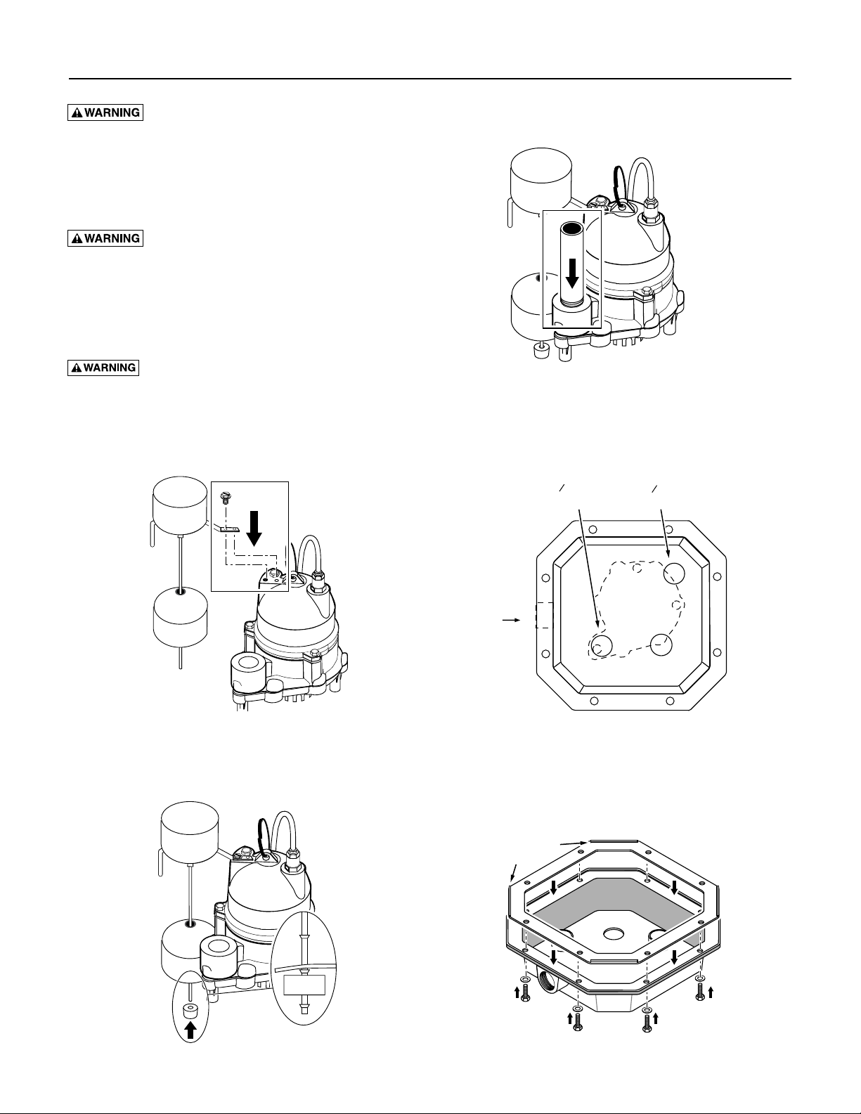
ASSEMBLY
Steps 1 and 2 (See Figure 1)
1
Step 4 (See Figure 3)
Install the discharge pipe hand-tight plus one-half turn.
3
Figure 3
Step 5 (See Figure 4)
Place the pump in the basin as shown. Align the discharge
with one of the threaded ports in the cover.
1
1 " NPT
2
Discharge
1
1 " NPT
2
Vent
Figure 1
Step 3 (See Figure 2)
Inlet
Pump
Basin
Figure 4
Step 6 (See Figure 5)
Turn the cover upside down and ‘lay in’ the basin gasket
as shown.
Locating
Cleats
Figure 2
2
Figure 5

Assembly / Installation 4
IMPORTANT: To prevent leaks, be sure that the cleats
on the corners of the basin gasket are up with the cover
upside down (that is, not pressed into the sealing face of
the cover).
Step 7 (See Figure 5)
Push the screws with their washers installed up through
the holes in the rim of the cover and in the basin gasket
(the cover will retain the screws).
Step 8 (See Figure 6)
• Align the cover with the discharge pipe and cords.
• Pull the cords through the non-threaded hole in the
basin cover.
• Place the cover over the discharge pipe.
• Install the cords in the cord grommet
• Install the cord/grommet assembly in the non-threaded
hole in the basin cover; don’t pull the cords tight.
1
1 " NPT
2
Discharge
1
1 " NPT
2
Vent
INSTALLATION (See Figure 7)
The basin (system) should be located at the lowest place
possible relative to the area to be drained.
NOTE: Make sure that the inlet of the pre-plumbed system
is lower than the water to be pumped.
Thread pipes into fittings;
don't go past end of threads.
1 " NPT
Vent
1/3 HP
Pump
1
2
1
/
8
15
"
1
1 " NPT
2
Discharge
1
1 " NPT
2
Inlet
3
/
13
"
4
12"
Vertical Float Switch
Cord Grommet
Inlet
Discharge
Pump
4720 1004
Figure 6
Step 9 (See Figure 6)
Fasten the basin cover to the basin with the capscrews
previously inserted in the cover (Step 7).
IMPORTANT: To prevent leaks, be sure the locating cleats
on the corners of the basin gasket are outside the edges of
the basin rim, not pressing against the rim.
12"
Figure 7 – Drainer Pre-Plumbed System Dimensions
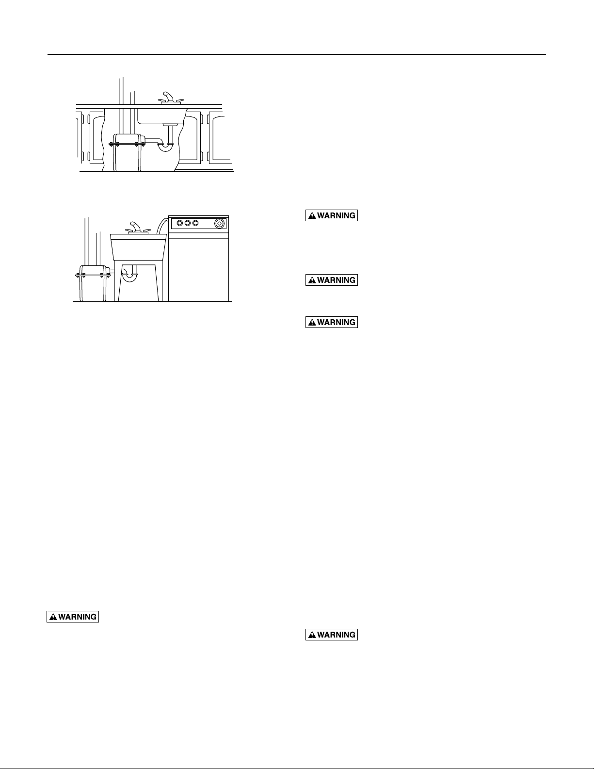
1. Install inlet pipe in opening as shown. Use RTV sealants
or PTFE pipe thread sealant tape to seal threads.
See Figures 8, 9, and 10, page 4 and 5, for typical
installation arrangements.
Discharge
Vent
Pump
Figure 8 – Typical installation to remove air conditioner
condensate or dehumidifier water
Installation / Maintenance 5
Discharge
Vent
Pump
Figure 9 – Typical wet bar installation
Discharge
Vent
Pump
Figure 10 – Typical installation for laundry sinks and
washing machines
2. Install discharge plumbing. When using rigid pipe,
use plastic pipe. Wrap thread with PTFE pipe thread
sealant tape. Screw pipe into discharge fitting hand
tight +1 – 1-1⁄2 turns.
NOTE: Do not use ordinary pipe joint compound on
plastic pipe. Pipe joint compound can attack plastics.
3. To reduce motor noise and vibrations, a short length
of rubber hose (1-7⁄8" I.D., e.g. radiator hose) can
be connected into discharge line near pump using
suitable clamps.
4. Install an in-line check valve to prevent flow
backwards through pump when pump shuts off.
5. Thread vent pipe into 1-1⁄2" NPT black vent fitting
in basin cover. Pipe should not extend into basin.
Connect vent pipe to sewer vent system.
6. Power Supply: Pump is designed for 115 V., 60 Hz.,
operation and requires a minimum 15 amp individual
branch circuit. Both pump and switch are supplied
with 3-wire cord sets with grounding-type plugs.
Switch plug is inserted directly into outlet and pump
plug inserts into opposite end of switch plug.
Hazardous Voltage. Pump should always be
electrically grounded to a suitable electrical ground such
as a grounded water pipe or a properly grounded metallic
raceway or ground wire system. Do not cut off round
ground pin.
7. If pump discharge line is exposed to outside subfreezing atmosphere, portions of line exposed must
be installed so any water remaining in pipe will drain
to the outfall by gravity. Failure to do this can cause
water trapped in discharge to freeze which could result
in damage to pump.
8. After piping and check valve have been installed, unit
is ready for operation.
9. Check operation by filling sump with water and
observing pump operation through one complete
cycle.
Risk of flooding. Failure to make this
operational check may lead to improper operation,
premature failure, and flooding.
MAINTENANCE
Risk of electric shock. Make certain that the
pump is unplugged before attempting to service or remove
any component.
Risk of electric shock. Do not handle a
pump or pump motor with wet hands or when standing
on wet or damp surface, or in water.
1. Keep pump inlet screen clear.
2. Shaft seal depends on water for lubrication. Do not
operate pump unless it is submerged in water as seal
may be damaged if allowed to run dry.
3. Motor is equipped with automatic reset thermal
protector. If temperature in motor should rise unduly,
switch will cut off all power before damage can be
done to motor. When motor has cooled sufficiently,
switch will reset automatically and restart motor. If
protector trips repeatedly, pump should be removed
and checked for cause of difficulty. Low voltage, long
extension cords, clogged impeller, very low head
or lift, etc., could cause cycling. Refer to Trouble
shooting Guide on Page 6 for additional information.
4. Periodically inspect pump, system components, and
sump for debris and foreign objects. Keep sump free of
all refuse. Perform routine maintenance as required.
Pump Cleaning
NOTE: Attempting to disassemble motor will void
warranty.
1. Use the pump ring to lift pump out of basin and place
pump on a clean level surface.
Risk of electrical shock. Shock can burn or
kill. Do not lift pump by power cord.
2. To clean impeller, remove eight screws holding
baseplate to motor assembly. Clean impeller as
necessary.
3. Re-install baseplate and screws.
4. Use pump ring to replace pump in basin.
Maintenance 6
Switch Replacement
Risk of electric shock. When servicing
pump, always disconnect power to electrical outlet and
remove pump electric cord from outlet.
cycle without interference from sidewall of basin,
plumbing, or any other object.
1. Mount bracket on switch housing using existing screws.
2. Slide rod into slot in bottom of switch housing. Fasten
rod into switch housing with pin.
housing; otherwise pump will not shut off.
NOTE: Pull gently on rod to make sure that it cannot
come out of switch housing.
Float must be able to complete its entire
Make sure pin holds float rod in switch
3. Mount switch assembly on pump using existing
screws. Make sure that nothing interferes with switch
operation.
4. Mount float on rod.
5. Install rod stop on bottom of rod.
6. Run pump through one complete cycle to verify
correct switch operation.
Risk of flooding. Drainer Pre-Plumbed
System comes with the automatic float switch mounted
on the motor housing ready for operation. Do not change
switch settings. Switch is set to start at approximately 6.5"
and to stop at approximately 2".
TROUBLESHOOTING
SYMPTOM POSSIBLE CAUSE(S) CORRECTIVE ACTION
Pump won’t 1. Blown fuse. 1. If blown, replace with fuse of proper size.
start or run.
check size of wiring from main switch on
property. If OK, contact power company or
hydro authority.
2. Low line voltage. 2. If voltage under recommended minimum,
Pump won’t 1. Restricted discharge 1. Remove obstacle in piping.
shut off. (obstacle in piping).
Pump operates 1. Restricted discharge 1. Remove obstacle in piping.
but delivers (obstacle in piping).
little or no water.
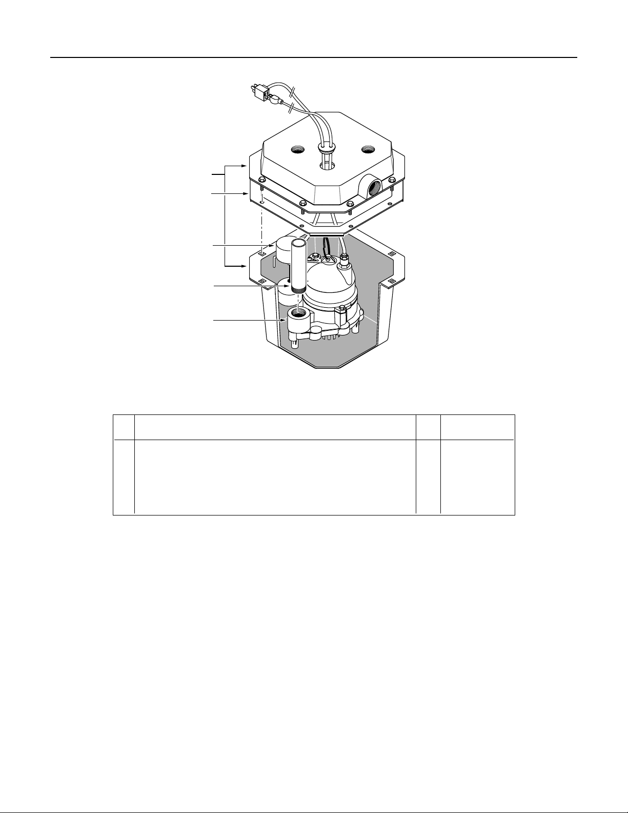
Repair Parts 7
1
2
3
4
5
Repair Parts List
Key Part
No. Description Qty. ED33V1
1 5 gallon Poly basin assembly (includes Key No. 2 and hardware kit) 1 PW73-64
2 Basin Gasket 1 U20-23
3 Automatic Vertical Float Switch 1 PKG 208
4 1-1/2" Discharge Pipe 1 U37-688P
5 1/3 HP Submersible sump pump 1 D33110V
• Hardware kit (includes bolts, washers, and cord grommet) 1 PW198-6
• Not illustrated.

Warranty 8
Limited Warranty
F.E. MYERS warrants to the original consumer purchaser (“Purchaser” or “You”) of the products listed below, that they will be free
from defects in material and workmanship for the Warranty Period shown below.
Product Warranty Period
whichever occurs first:
Jet pumps, small centrifugal pumps, submersible pumps and relatedaccessories
Fibrewound Tanks 5 years from date of original installation
Steel Pressure Tanks 5 years from date of original installation
Sump/Sewage/Effluent Products
12 months from date of original installation,
or 18 months from date of manufacture
12 months from date of original installation,
or 24 months from date of manufacture
Our warranty will not apply to any product that, in our sole judgement, has been subject to negligence, misapplication, improper
installation, or improper maintenance. Without limiting the foregoing, operating a three phase motor with single phase power
through a phase converter will void the warranty. Note also that three phase motors must be protected by three-leg, ambient
compensated, extra-quick trip overload relays of the recommended size or the warranty is void.
Your only remedy, and F.E. MYERS’s only duty, is that F.E. MYERS repair or replace defective products (at F.E. MYERS’s choice). You
must pay all labor and shipping charges associated with this warranty and must request warranty service through the installing
dealer as soon as a problem is discovered. No request for service will be accepted if received after the Warranty Period has
expired. This warranty is not transferable.
F.E. MYERS SHALL NOT BE LIABLE FOR ANY CONSEQUENTIAL, INCIDENTAL, OR CONTINGENT DAMAGES WHATSOEVER.
THE FOREGOING LIMITED WARRANTIES ARE EXCLUSIVE AND IN LIEU OF ALL OTHER EXPRESS AND IMPLIED WARRANTIES,
INCLUDING BUT NOT LIMITED TO IMPLIED WARRANTIES OF MERCHANTABILITY AND FITNESS FOR A PARTICULAR
PURPOSE. THE FOREGOING LIMITED WARRANTIES SHALL NOT EXTEND BEYOND THE DURATION PROVIDED HEREIN.
Some states do not allow the exclusion or limitation of incidental or consequential damages or limitations on the duration of an
implied warranty, so the above limitations or exclusions may not apply to You. This warranty gives You specific legal rights and You
may also have other rights which vary from state to state.
This Limited Warranty is effective June 1, 2011 and replaces all undated warranties and warranties dated before June 1, 2011.
F.E. MYERS
293 Wright Street, Delavan, WI 53115
Phone: 888-987-8677 • Fax: 800-426-9446 • www.femyers.com
In Canada: P. O. Box 9138, 269 Trillium Dr., Kitchener, Ontario N2G 4W5
Phone: 519-748-5470 • Fax: 888-606-5484
 Loading...