


MODEL BX
INDUSTRIAL PUMPS
INSTALLATION AND SERVICE MANUAL
NOTE! To the installer: Please make sure you provide this manual to the owner of the equip ment or to the responsible
party who maintains the system.
Part # 13800A903 | © 2012 Pentair Pump Group, Ltd. | 11/12/12

GENERAL INSTRUCTIONS
Reciprocating pumps of both the plunger and piston
type are positive displacement in principle. Due to
positive displacement characteristics, problems may
arise through improper installation or application.
When new or unusual installations are planned, or
the material to be pumped is a liquid other than
cold water, the customer should consult the “Myers
Reciprocating Pump Manual” or factory for additional
information.
CAUTION: Positive Displacement Pumps must
have a proper size and operable type of pressure
regulating valve or pressure relief valve piped into
the discharge line. This is mandatory to prevent
damage to pump and piping or possible injury
to personnel. Do not install any valves or shutoff
devices in the bypass line from pressure regulator
to tank or supply.
CAUTION: All pumps should be installed level.
For mobile applications the maximum angle of
intermittent operation should be no more than
5 degrees in any one direction.
CALIFORNIA PROPOSITION 65 WARNING:
This product and related
accessories contain chemicals known to the
State of California to cause cancer, birth
defects or other reproductive harm.
1. INSTALLATION
A. If possible, install suction piping one pipe size
larger than suction tapping in pump. Reduce
piping size at pump with a reducer coupling.
A suction surge arrester will assure smoother
operation.
B. Keep suction piping as short and simple as
possible with a minimum of lift. Avoid any high
points in the suction line. Suction piping must not
have any air leaks. Check suction piping assembly
for leaks by using 20–80 PSI air pressure and soap
bubbles or submerging assembly under water.
C. Use suction strainer and screen with twice the
rating of the pump capacity to avoid restriction
of the pump suction. Strainer mesh should be
sufficiently small to prevent passage of trash
which may lodge under pump valves. Keep screen
clean with a regular maintenance schedule to
avoid starving of pump suction. A starved suction
condition is usually indicated by excessive pump
shock and noise. Many pump problems and many
packing or cup failures are directly traceable to a
starved suction condition.
D. When pumping liquids that are heated, reduce
pump speed to avoid suction problems. Consult
“Myers Reciprocating Pump Manual” or factory for
temperature and speed limitations.
E. Make sure that drive is adequate for horsepower
required and that drive is properly aligned and
tensioned. With belt drives, pulley on both motor
and pump should be located as close as possible
to bearing to reduce bearing and shaft bending
loads.
CAUTION: Be sure that pump belts and pulleys
are properly protected by guards according to
industrial code within state of application.
F. Make sure that all bolts, nuts, set screws and keys
are properly tightened.
G. Be sure that discharge line is properly protected
by means of a pressure regulating valve and a
discharge surge arrester of proper size, capacity
and pressure rating. The discharge line should be
of comparable size to discharge tapping in pump.
Average discharge line velocity should not exceed
5 feet per second for most satisfactory operation.
H. Nozzle capacity or demand should not exceed
90% of pump capacity for satisfactory regulating
valve operation. Nozzling in excess of this capacity
may cause unstable pressure regulator operation.
It is also preferred to nozzle in excess of 50% of
pump capacity to reduce rate of erosion or wear
on regulating valve and seat. When lower system
demands (than rated pump capacity) are required
in an installation, the pump speed should be
reduced by changing drive ratios. This will reflect
savings in power consumption, reduced regulating
valve wear and extended pump life.
I. Where line shock or water hammer is encountered
a second surge arrester should be installed in the
discharge line adjacent to spray gun or nozzles.
Under some conditions it may also be desirable
to isolate pump from piping with a suitable high
pressure hose. This will eliminate transmission of
line vibration to the pump, reducing possible failure
of piping, pipe threads, and/or pump casting.
J. Never pipe the bypass from a pressure regulating
valve back into the pump suction. When the
discharge line is shut off, the complete bypass is
circulated back into pump suction with a resulting
rapid temperature rise which will destroy the piston
packing. It is permissible to pipe the bypass from
an unloader into the suction because the pump
pressure is unloaded when discharge is shut off.
2. STARTING PUMP
A. Before starting read all instructions carefully!
1. Replace all drain plugs in pump and piping.
2. Fill pump crankcase with recommended oil to
the proper level. (See Lubrication Section.)
3. Inspect tank to be sure that no foreign material
is in tank or suction line.
4. Fill tank at least half full or connect suction to
water supply. Open valve (if present) in suction
line. If pumping from a pit, make sure that
suction line is completely submerged.
13800A903 11/12/12
2
5. Make sure all valves, including spray gun or
nozzles, are open in discharge line. Spray gun
may be anchored to discharge back into tank.
6. Completely back off pressure adjusting screw
on pressure regulating valve.
CAUTION: When pumping from a pit or under a
suction lift condition, if pump does not prime in
a short period, fill the discharge side of fluid end
with water to seal discharge valves. If pump still
does not prime remove suction hose and fill pump
with water. Dry operation will cause heating and
wear on cylinders and packing. Be sure that an
operating pressure gauge is located on discharge
line.
SAE 40 should be used. Use only good quality grade
oils with SAE designation MS, SC or SD. Maintain
level at mark on cover for the required RPM. Foaming
or milky discoloration of oil is an indication of water.
Oil should be replaced to preclude possible damage
to crankcase and components.
NOTE: Drain oil from crankcase after first 30 hours
of operation. It is best to always drain the oil when
it is still hot. Refill the new oil as mentioned above.
Run pump at full speed under no pressure for 2 or
3 minutes before returning to operation. Thereafter
change oil every 300 hours or immediately if water
droplets are found in crankcase. Check oil level
regularly and add oil as needed.
B. Starting Unit:
1. After starting, close discharge valve or gun
slowly while watching pressure gauge to
make sure relief valve or unloader is operating
properly.
2. Adjust relief valve to desired pressure. See
regulator instructions.
3. Cycle nozzles or gun on and off to be sure that
pressure adjustment and regulator operation is
satisfactory.
LUBRICATION
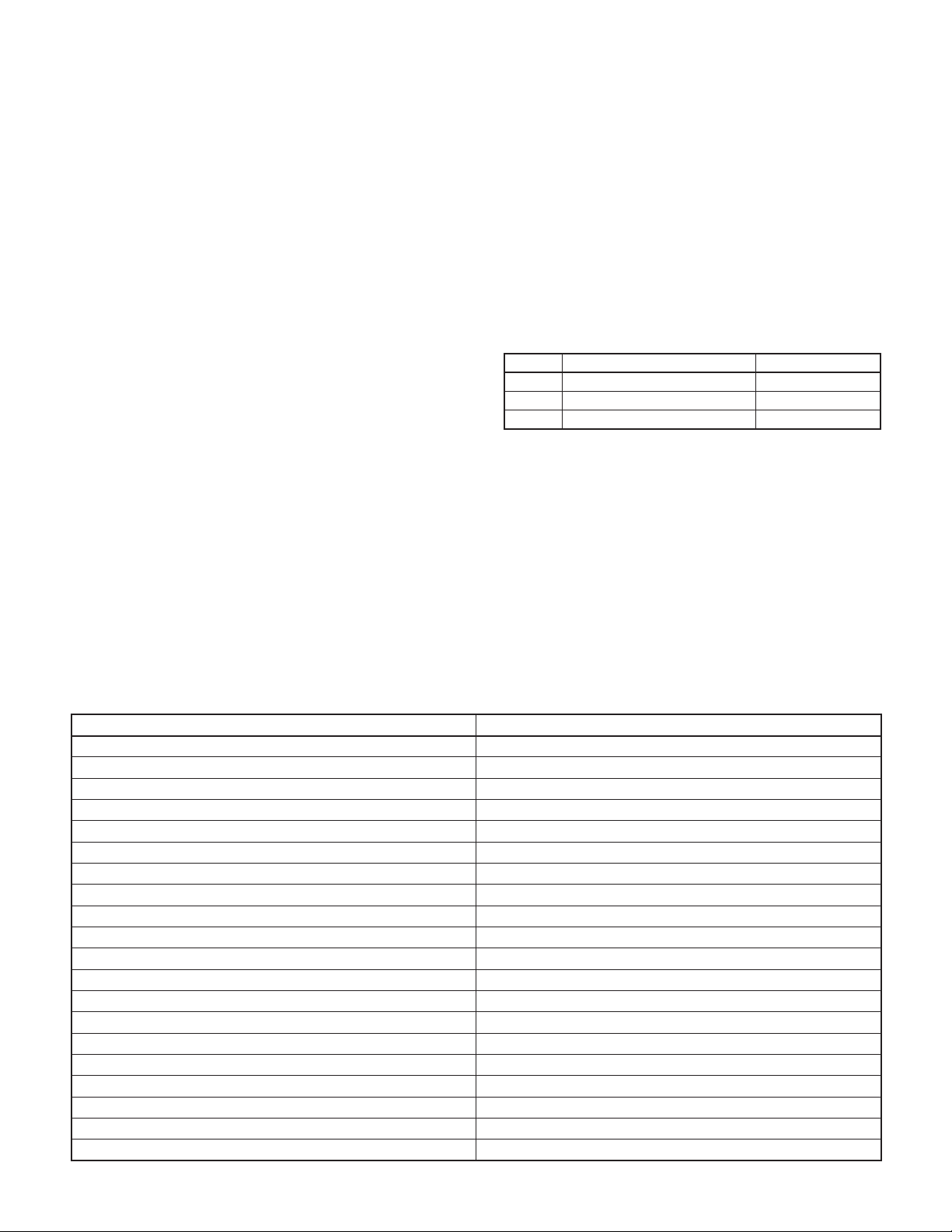
Pump-Crankcase must be filled with 2 to 3 pints
depending on RPM (See Table) of SAE 30 oil unless
ambient temperature exceeds 90 degrees F when
RPM OIL LEVEL LOCATION OIL CAPACITY
800 Add Level Mark 32 oz.
700 Between Add & Full Mark 40 oz.
600 Full Mark 48 oz.
Speeds of 400 to 600 RPM require 48 ounces of oil.
For speeds less than 400 RPM consult factory for
recommendations.
Avoid Freezing by draining all water from pump
and system in cold weather. This can be done by
breaking suction connections and turning crankshaft
over 4 or 5 times, or the fluid end can be removed to
completely drain cylinders and fluid end.
SPECIFICATIONS
TYPE TRIPLEX – SINGLE ACTING
Rated Capacity GPM @ 800 RPM 8 GPM
Pressure Rating: Continuous/Intermittent 1,000 PSI/1,200 PSI
Required BHP @ 800 RPM and Rated Pressure 6.3
Temperature Rating (Max.) 140˚ F
Cylinder Bore 1"
Stroke 1-1/16"
Suction Size 1 NPT (Bottom)
Discharge 3/4" NPT (Top)
Crankshaft Diameter 1"
Keyway 1/4 x 1/8
Cylinder Material Alumina Ceramic
Fluid End Material Brass
Packing Material High Acrylic Nitrile
Valve Material Stainless Steel
Seat Material Stainless Steel
Piston Material Brass
Approximate Shipping Weight 50 lbs.
Recommended Regulator 22900B000
Recommended Unloader 19280C000
Recommended Discharge Surge Suppressor 6CU
3
13800A903 11/12/12
 Loading...