

Pentair Mi Series Installation, Maintenance And Operation Manual
Mineral insulated (Mi)
series Heating systeMs
Installation,
Maintenance and
Operation Manual
THERMAL MANAGEMENT
EN-PyrotenaxMI-IM-DOC586 R4
2
1
2
3
4
5
6
7
8
9
10
11
General information 4
Heating cable selection and storage 7
Heating cable installation 9
Components selection and installation 23
Temperature control and limitation 24
Thermal insulation and marking 27
Power supply and electrical protection 31
System testing 32
Operation, maintenance and repairs 33
Trouble Shooting 34
Installation Record Sheet 35
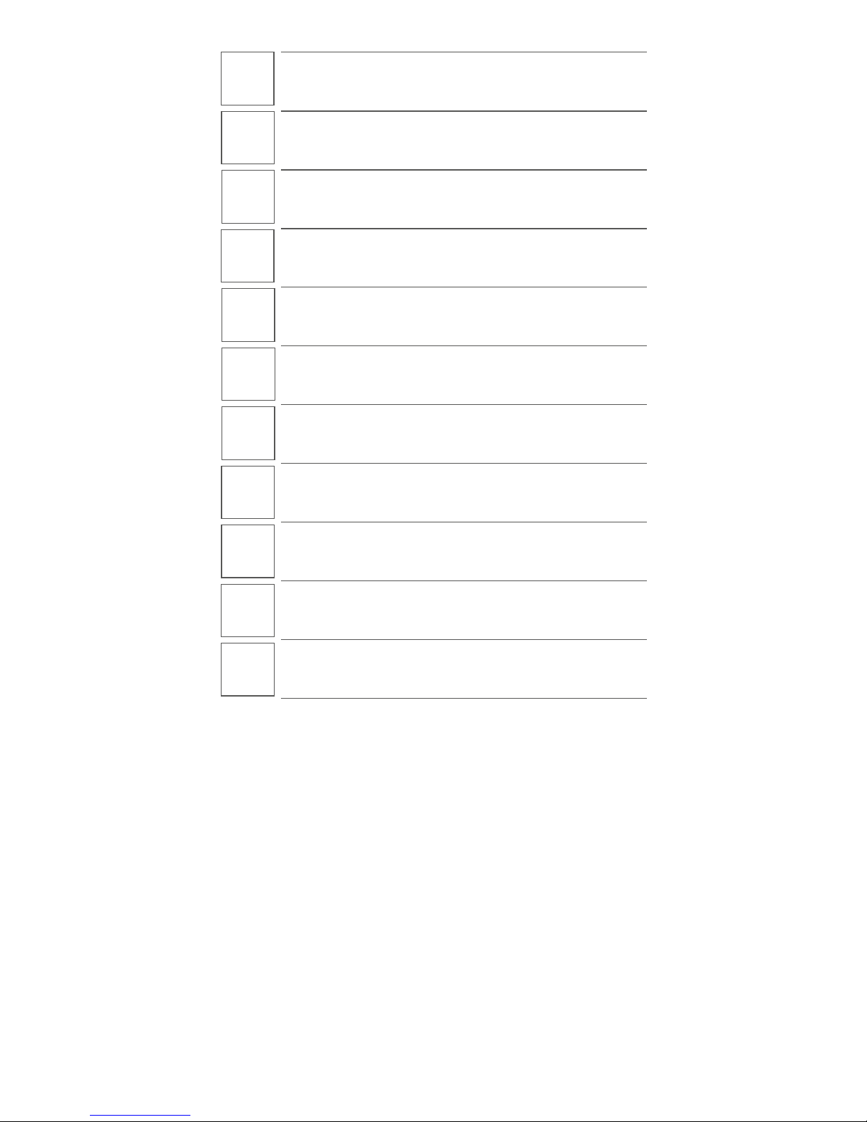
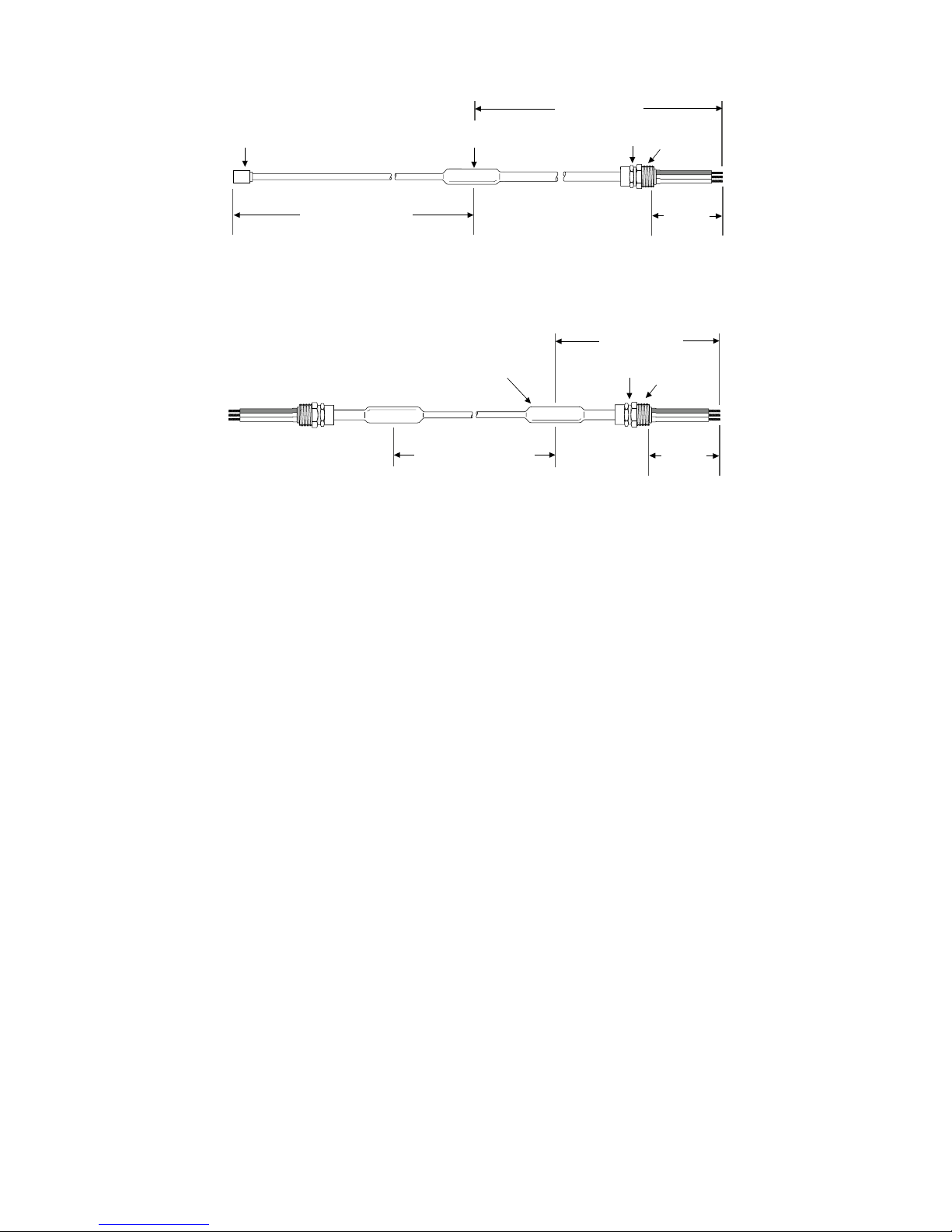
Typical configuration for MI-heating cable system
(single conductor)
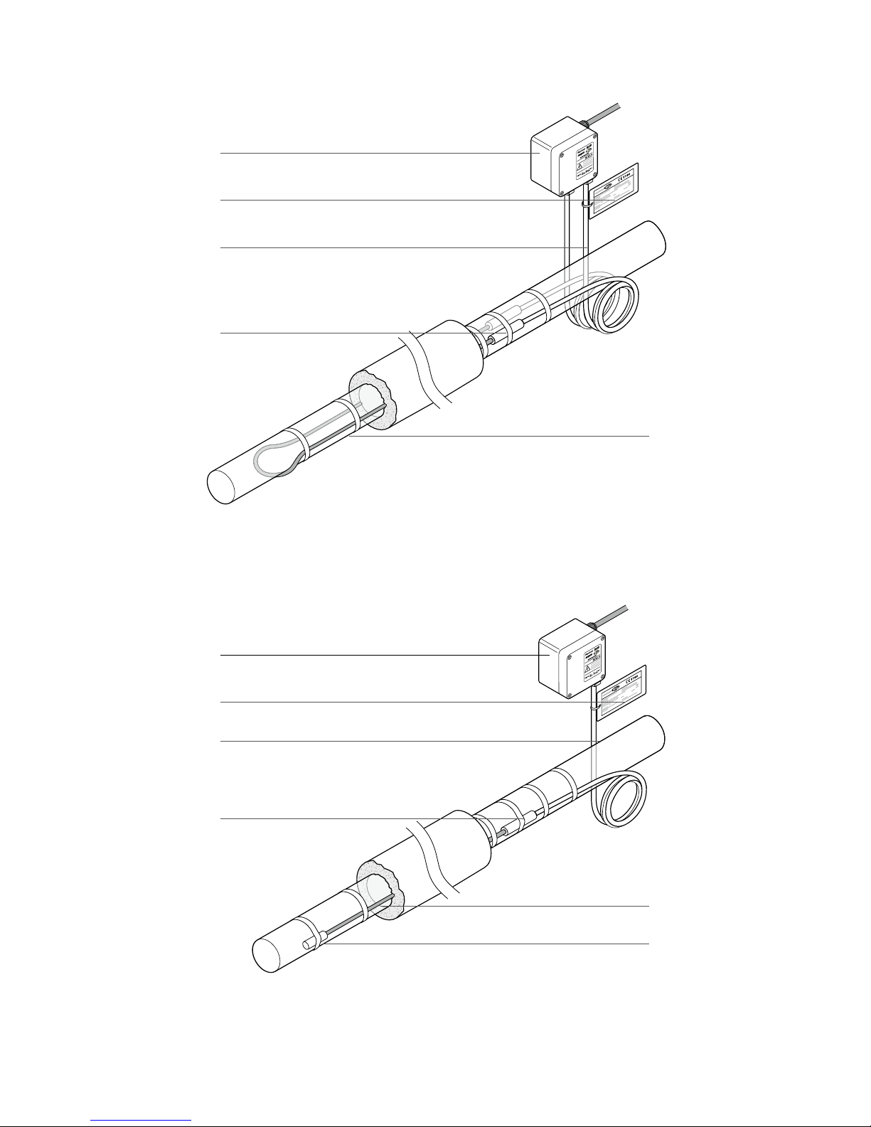
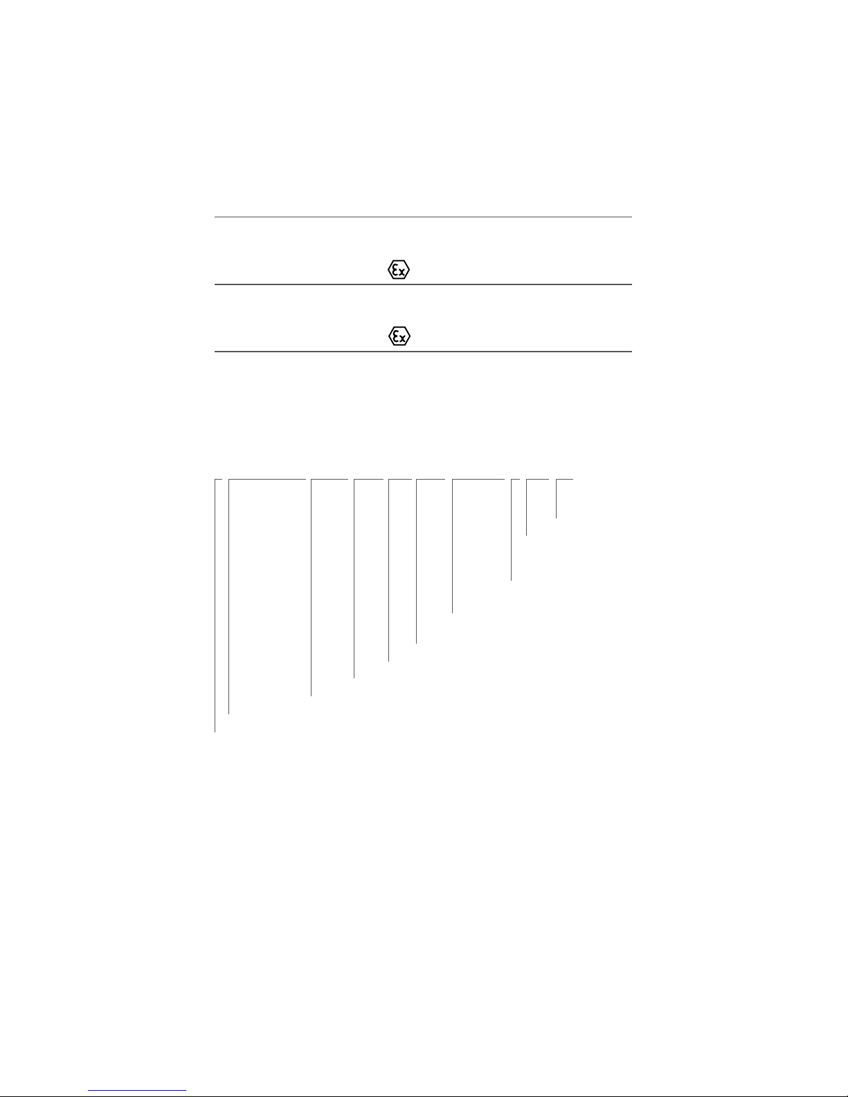
Typical configuration for MI-heating cable system
(dual conductor)
Junction box
MI cold lead cable (single conductor)
Circuit identification tag
Hot/cold joint
MI cold lead cable (dual conductor)
Hot/cold joint
Circuit identification tag
Junction box
Dual conductor
MI heating cable
End cap
Loop of MI heating cable
(single conductor)
3
1 GENERAL INFORMATION
Use of the manual
This Installation and Maintenance manual applies to Pentair Thermal
Management Mineral Insulated (MI) series resistance heating cable systems
installed on thermally insulated pipes and vessels and associated equipment.
In particular it refers to mineral insulated (MI) series heating systems, which
feature a specific power output depending on various design parameters,
in particular, cable length and voltage. This manual provides general
information and shows an overview of the most common installations and
applications on MI as well as typical examples. In any case the information
provided for specific projects will take precedence over this manual. In case of
conflicts, please contact your Pentair Thermal Management representative.
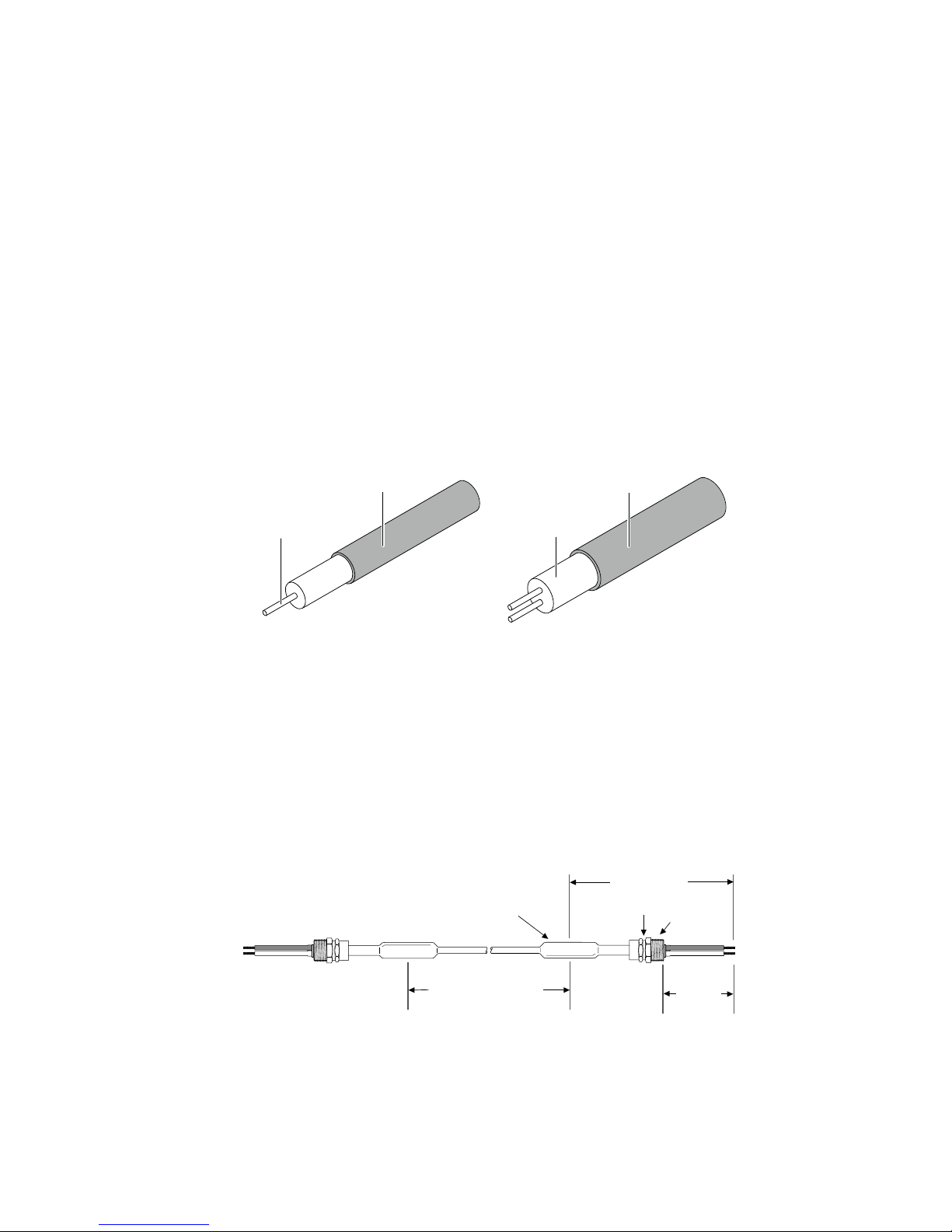
Pentair Thermal Management offers two different cable constructions for
electrical heat-tracing purposes: single conductor cables, which are typically
laid in loop configurations and dual conductor cables, which are typically laid
in single runs.
Figure 1: Typical cable construction
Various types of the MI bulk heating cables are available:
HCC/HCH: Copper sheathed MI heating cables
HDF/HDC: Cupro-nickel sheathed MI heating cables
HSQ: Stainless steel sheathed MI heating cables
HAx: Alloy 825 sheathed MI heating cables
HIQ: Inconel sheathed MI heating cables
Figure 2: Typical heating unit designs
Design type B
Single conductor
Heating
conductor(s)
Insulation
(magnesium oxide)
Single-conductor cable
Dual-conductor cable
Metal sheath
Metal sheath
Potted seal
Heating cable length
Hot/cold joint
Cold lead cable
(standard 2 m)
300 mm
Flexible
tail length
Gland
4
Design type D
Dual conductor
Design type E
Dual conductor
The joints can be either brazed or laser welded, refer to Pentair Thermal
Management product literature for more detailed information.
Please note that this manual only covers the installation of prefabricated MI heating units. The complete termination process and
repair of heating cable units is not covered by this manual and must be
carried out by qualified and experienced personal only.
For more information contact your Pentair Thermal Management
representative.
Important
For the Pentair Thermal Management warranty to apply, the
instructions of this manual must be followed. Design, installation,
inspection, operation and maintenance must be in accordance with the
standards IEC 60519,
IEC 62086, EN 50019 and EN60079-7 (where applicable). Other local
requirements and national electric codes applicable to electrical heattracing systems must be followed as well. The thermal safety class is 2
(to IEC 60519-2).
Personal involved in the installation, testing and maintenance of electric
heat-tracing systems must be suitably trained in all special techniques
required, as well as in general electrical installation work. All work
should be monitored by supervisors experienced in heat-tracing
applications.
300 mm
Flexible
tail length
Potted seal
Heating cable length
Hot/cold joint
Gland
End cap
Cold lead cable
(standard 2 m)
300 mm
Flexible
tail length
Potted seal
Heating cable length
Hot/cold joint
Gland
Cold lead cable
(standard 2 m)
5
Area Classification – Ordinary
HCC/HCH/ HDC/HDF/HSQ/HAx/HIQ
Area Classification – Hazardous, Zone 1 or Zone 2
Special conditions for safe use in hazardous area:
Please refer to relevant hazardous area certifications
Certificate No. Code Nos.
HCC/HCH/HDC/HDF/HSQ/HAx/HIQ
(heating elements)
Baseefa 02ATEX0046X II 2 G EEx e II T6 to T1
HCC/HCH/ HDC/HDF/HSQ/HAx/HIQ
(bulk cable)
Baseefa 02ATEX0045U II 2 G EEx e II T6 to T1
For other national approvals please contact Pentair Thermal
Management.
The order reference of MI heating units uses
the following nomenclature
When ordering, the complete order reference of the MI heating unit
needs to be provided. For hazardous areas, information must also
be provided about the T-rating and temperature data relevant to the
application (max. sheath temperature data) to enable the correct
representation of data on hazardous area tags attached to the completed
heating unit in the factory. Before installation, check the suitability of the
heating units supplied. Changes to any of the parameters may require a
re-design and must be confirmed before installation.
B/HSQ1M1000/43.0M/1217/230/2.0M/SC1H2.5/X/M20/EX
Area classification:
EX, ORD
Gland size M20, M25, etc...
Hot/cold joint material type:
X -stainless steel, Y - brass,
LW - laser welded
Cold lead size and sheath type
(see table on next page)
Cold lead length: M for unit in meters
(standard is 2 m)
Heating unit: Operating voltage
Heating unit: total wattage in W
Unit length: M for unit in meters
Heating cable reference
Heating cable unit type: Type B, D or E
6

2 HEATING CABLE SELECTION AND
STORAGE
The selection of the proper heating cable and components, best suited
for the application must be checked against the relevant product
literature, the most important product properties are summarized in
following table:
Table 1: Properties of MI heating units
Please check against individual datasheet or contact Pentair Thermal
Management for further details.
The maximum cable power output is directly dependant on the
application and control method used. The actual limits of MI heating
cables in a specific application are given in Pentair Thermal Management
Engineering Software (e.g. TraceCalc Pro design software). For more
details, please contact Pentair Thermal Management.
Ensure that the heating cable voltage and temperature rating is suitable
for the application.
MI Heating Cable Type HCC/ HCH HDC/ HDF HSQ
Number of conductors 1 1 1
Maximum voltage (U0/U) 300 / 500 V
Maximum withstand temp.(1)
Brazed heating unit 200°C 400°C 450°C
Laser welded heating unit – – 700°C
Temperatureclassification T6 – T3 T6 – T2 T6 – T1
Minimum cable spacing 25 mm
Minimum installation temp. –60°C
Minimum bending radius 6 x Cable Diameter
Chemical resistance Low Medium Medium
MI Heating Cable Type HAx1N HAx2N HAx2M HIQ
Number of conductors 1 2 2 1
Maximum voltage (U0/U) 346/600 V 300/300 V 300/500 V
Maximum withstand temp.(1)
Brazed heating unit 450°C 450°C 450°C 450°C
Laser welded heating unit 650°C 650°C 650°C 700°C
Temperature classification T6 – T1 T6 – T1 T6 – T1 T6 – T1
Minimum cable spacing 25 mm
Minimum installation temp. –60°C
Minimum bending radius 6 x Cable Diameter
Chemical resistance High High High High
(1)
The hot-cold junction used in a heating unit may lead to temperature
limits below the limit of the heating cable. Contact Pentair Thermal
Management if the exposure temperature exceed values given in
the tables above for more detailed instructions how the unit can be
installed under those circumstances.
7
Changing design parameters such as voltage or cable length will result
in a different power output and maxi-mum sheath temperature. This
may require a redesign of the entire system.
To prevent fire or explosion in hazardous areas, verify that the
maximum sheath temperature of the heating cable is below T-class
or auto-ignition temperature of the gases present in those areas. For
further information, see design documentation (e.g. TraceCalc Pro
reports).
For the evaluation of the chemical resistance of MI heating cables (for
corrosion aspects), refer to our product datasheets or contact Pentair
Thermal Management for assistance. Check the design specification to
make sure the correct heating cable is installed on each pipe or vessel.
Refer to Pentair Thermal Management product literature to select an
appropriate heating cable for each thermal, chemical, electrical and
mechanical environment.
Storage
Store MI heating units in a clean, dry place.
Protect the heating cable from moisture and mechanical damage.
Storage below 10°C may result in surface condensation,
potentially causing low insulation resistance.
After extended storage, it is strongly recommended to measure
the insulation resistance of MI heating units prior to installation,
also refer to section 8.
8

3 HEATING CABLE INSTALLATION
Warning
As with any electrical equipment or wiring installation that operates at
line voltages, damage to heating cable and components, or incorrect
installation that allows the penetration of moisture or contamination
can lead to electrical tracking, arcing and potential fire hazard. In case
of damage and later repair on site any unconnected heating cable end,
exposed to the environment, must be sealed appropriately.
3.1 Pre-installation checks
Check design recommendations:
Verify that you have all required engineering documents
supporting the installation
Check for any special instructions in engineering documentation
(e.g. cover with aluminium foil, use of metal mesh, fixation etc...).
Verify that hazardous area information given in engineering
documentation is compatible with the area classification the
material will be installed in.
Check materials received:
Inspect heating cable and components for in-transit
damage.
Review the heating cable design and compare the list of designed
materials to the catalogue numbers of heating cables and
electrical components received to confirm that proper materials
have been received on site. The heating cable type and hazardous
area marking (if applicable) is printed on a tag label supplied with
each heating element.
Measure and note down the electrical resistance and the
insulation resistance of the cable. Compare these values to those
in the design documents (see section 8).
Check equipment to be traced:
Check identification, length and diameter of pipework/
vessel against the design documents. Also verify, that actual
temperatures and insulation properties are in alignment with the
design documentation.
Ensure all pressure testing of pipework/ vessel is complete and
final paint and pipe coatings are dry to touch.
Walk the system and plan the routing of the heating cable on
the pipe, including tracing of heat sinks. e.g. valves, flanges,
supports, drains etc.
9
Inspect piping for burrs, rough surfaces, sharp edges
etc. which could damage the heating cable. Smooth off
or cover with layers of aluminium foil. At elevated sheath
temperatures consider the use of stainless steel foil.
(e.g. HSQ; HIQ or HAx).
Surface areas where heat-tracing is to be installed must be
reasonably clean. Remove dirt, rust and scale with a wire brush
and oil and grease films with a suitable solvent.
3.2 Heating cable pulling and laying
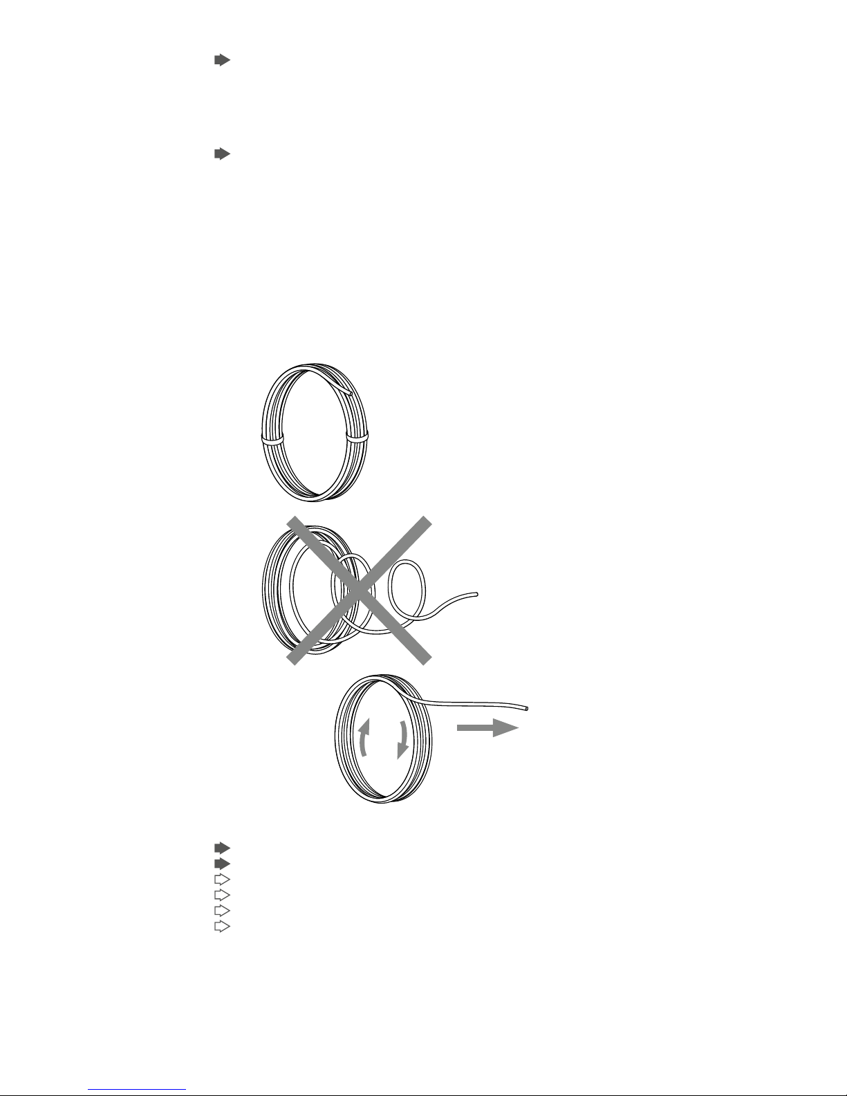
Heating cable pulling tips:
Figure 3: Importance of cable pulling direction
Avoid distortion of the cable and kinking.
When pulling the heating cable, avoid:
sharp edges
excessive pulling force
kinking and crushing
running over it with equipment.
The minimum bending radius of the heating cable must be respected.
10
Figure 4 : Minimum bending radius of MI heating cables
Do not repeatedly bend and straighten the cable.
Keep heating cable strung loosely but close to the pipe being
traced, to avoid interference with supports and other equipment.
Add additional heating cable to trace the fittings and supports as
required by the design specification or engineering documents.
Leave the appropriate amount of heating cable at all power
connection, splice and tee locations.
Do not bend the cable within 150 mm of the hot to cold junction
or remote terminations.
When installing MI and other constant wattage heating cables,
ensure that they do not overlap or cross. Doing so may lead to
local over-heating and hazard of fire.
Figure 5 : Minimal spacing must be respected
Minimum cable spacing: 25 mm (lower spacings may be possible but
require special attention and must be properly documented in the
engineering documentation).
For installation in hazardous areas, the standard minimum spacing is
50 mm. This must be respected, unless lower spacings are specifically
allowed in the engineering documentation.
6 x ∆
Cable ∆ > 6 mm
11

Table 2: Typical allowances (in mm) per run of cable
NPS
inchDNmm
Light
valve
(flanged)
Light
valve
(threaded
or welded)
Heavy
valve
(flanged)
Heavy
valve
(threaded
or welded)
Typical
pipe
shoe
Flange
pair
Field
variance
0.5 15 300 300 300 300 910 300 2%
0.75 20 460 300 460 300 910 300 2%
1 25 610 300 610 300 910 460 2%
1.5 40 760 460 910 460 910 460 2%
2 50 760 610 1060 610 910 460 2%
3 80 910 760 1220 760 910 610 3%
4 100 1220 910 1520 910 910 610 3%
6 150 1520 1060 1830 1060 910 610 3%
8 200 2140 1220 2440 1220 910 610 3%
10 250 2440 1520 3050 1520 910 910 3%
12 300 2750 1830 3660 1830 910 1060 3%
14 350 3050 2140 4270 2140 1370 1220 3%
16 400 3350 2440 4880 2440 1370 1370 3%
18 450 3660 2750 5500 2750 1370 1680 3%
20 500 3970 3050 6100 3050 1370 1830 3%
24 600 4580 3660 7320 3660 1370 2140 3%
1. Allowances above are based on typically available fittings and
supports, with an insulation thickness equivalent to the pipe
insulation. Please refer to the engineering documentation for project
specific allowances.
2. For pipes requiring more than one run of heating cable, apply the
full allowance for each run of cable on each fitting or support as
long as space allows. However, MI heating cables must not touch or
overlap and the minimum spacing between the heating cables must
be respected.
3. For some applications, it may be physically impossible to install all
of the recommended heating cable directly on the fitting or support.
In this case, install the excess heating cable on the pipe, on either
side of the fitting or support, or distribute the additional heater
length along the entire circuit length if a lower local temperature
is acceptable. This constraint may be difficult for small pipes
and/or multiple cable runs. If required, contact Pentair Thermal
Management for assistance.
4. The field variance is important to accomodate expansion and
contraction of the heated equipment. Also refer to figures 12-14 for
more detailed information.
1212
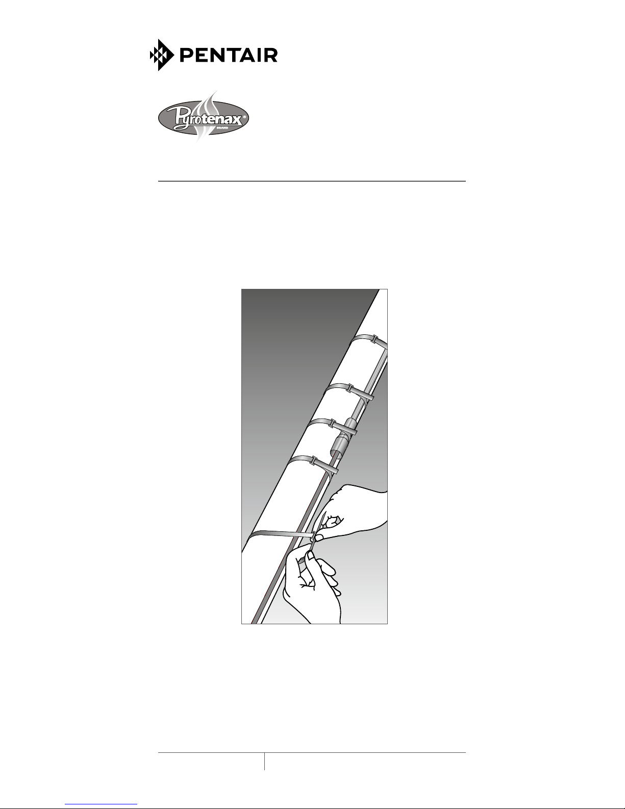
3.3 Heating cable attachment
Fix in place with metal bandings, tie wire or wire cloth band at a
typical interval of 300 mm and additionally where necessary.
The use of tie wire with softer sheath MI heating cables (like
copper HC and cupro-nickel HD) should be avoided, as the tie wire
can damage the heating cable surface over time. Do not tighten
tie wire, use wire cloth band wherever possible.
The hot to cold junction should be secured with metal bands at a
typical distance of 150 mm on either side of the joints.
Cable must be installed and fixed such that movement of cable
during its heating up cycles is permitted, but not to allow cable
to move freely under its own weight. Other attachments (like
aluminium tape or glass tape) may be used, if specified in the
design documentation.
The heating cables may be installed in straight, multiple runs as
required by the design specification.
On horizontal pipes fix on lower quadrant as shown below and not
on bottom of pipe.
Figure 6 : Cable orientation on pipe
On vertical pipe sections fix the heating cables equally distributed
around the pipe circumference.
Read the design documents, in particular concerning the need
for cable allowances and regard the location of junction boxes/
controllers before permanently attaching the cable to the pipe.
Weatherproof
jacket (typ)
Insulation
(typ)
Cable
Pipe
One heating cable
Cable
Cable Cable
Cable
Two heating cables
Cable
Temperature
sensor
Temperature
sensor
Temperature
Sensor
1313

Verify if the design documentation requires that the heating
cables have to be covered by aluminium or stainless steel foil
before the insulation is applied.
Installation on tanks typically requires additional fixing devices as
pre-punched steel strips as shown below:
Figure 7: Typical cable layout on large surfaces like tank walls
Figure 8: Fixing device: pre-punched metal strap
Avoid sharp edges and properly seal penetration of MI cold lead
cables through the insulation cladding.
14
Cold
leads
Junction
box
Temperature
controller
Heating cable
Temperature
sensor
Banding
Prepunched
strapping
 Loading...