

Meteor High Rate Sand Filter O w ner's Manual
IMP
ORTANT SAF ETY INS
TRU
CTION
S
READ
A
N
D
FOLLOW
S
AVE THESE INS
ALL I
TRU
NSTRU
CTION
CTION
S
S
Table of Contents
SECTION I. FILTER INSTALLATION. ...........................................................................................................2
SECTION II. FILTER OPERATION AND CLEANING. .................................................................................3
SECTION III. START-UP PROCEDURE ...........................................................................................................5
SECTION IV. CLEANING FREQUENCY..........................................................................................................5
SECTION V. FILTER BACKWASH PROCEDURES. .....................................................................................5
SECTION VI. WINTERIZING THE FILTER. ....................................................................................................7
SECTION VII. EQUIPMENT MAINTENANCE.................................................................................................7
SECTION VIII. TROUBLESHOOTING. ...............................................................................................................8
SECTION IX. TECHNICAL DATA. ...................................................................................................................9
A. REPLACEMENT PARTS, MODEL'S 18 and 20 in. ............................................................................................................... 9
B. REPLACEMENT PARTS, MODELS 22, 26, and 30 in. .......................................................................................................... 9
SECCIÓN I. CÓMO FUNCIONA SU FILTRO. ............................................................................................12
SECTION I. MODE DE FONCTIONNEMENT DU FILTRE. ...................................................................... 20
W ARNING
Before installing this product, read and follow all warning notices and instructions accompanying this product. Failure to follow
safety warnings and instructions can result in severe injury, death, or property damage. Call (800) 831-7133 for additional free
copies of these instructions.
Important Notice
Attention Installer.
This manual contains important i nformation about the installation, operation and safe use of this
product. This information should be given to the owner/operator of this equipment .
Pentair Pool Products
1620 Hawkins Ave., Sanford, NC 27330 • (919) 774-4151
10951 West Los Angeles Ave., Moorpark, CA 93021 • (805) 523-2400
Re v. C 5-11-01 1 P/N • Núm/Pt e. • Réf. 9910200 0
SECTION I. FILTER INSTALLATION.
1. The filter should be mounted on a level concrete slab. Position the filter
so that the instructions, warnings and pressure gauge are visible to the
operator. Also, position the filter so that the piping connections, control
valve and drain port are convenient and accessible for servicing and
winterizing.
2. Install electrical controls (e.g., on/off switches, timers, control systems,
etc.) at least five (5) feet from the filter. This will allow you enough
room to stand clear of the filter during system start up.
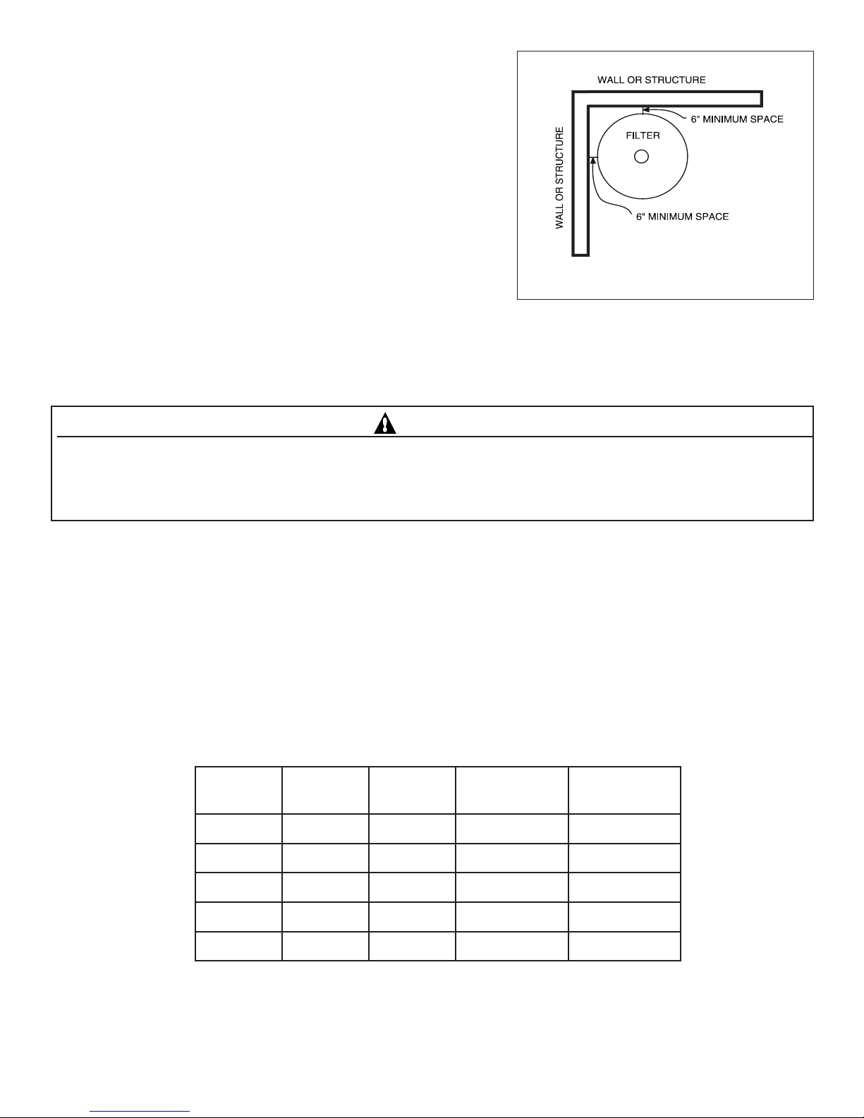
3. Provide sufficient clearance around the filter to permit visual
verification that the clamp is properly installed, see Figure 1.
4. Provide sufficient space above the filter to remove the control valve for
cleaning and servicing. This distance will vary with the model of filter you are using. See Table 1 for the required verticl
clearance.
5. Make all plumbing connections in accordance with local plumbing and building codes. Filter plumbing connections are
provided with an O-ring seal. Use only a silicone based lubricant on the O-rings. Do not use pipe joint compound, glue or
solvent on the bulkhead connections to avoid damage to the O-rings.
Figure 1.
C A UTION
For Multiport control valves with threaded ports use only Teflon tape, 100% pure Teflon paste (non-petroleum base
)
,
Permatex #2 sealant on all threaded pipe connections, except fittings with O-rings. Use of other pipe joint compounds can
damage components of this system and cause leaks. For control valves with slip ports, use only ABS to PVC solvent welding
adhesi ve.
6. For the maximum working pressure of this filter see Table 1. Never subject this filter to pressure in excess of this amount even when conducting hydrostatic pressure tests. Pressures above maximum working pressure can cause the valve or other
plumbing to be blown off, which can result in severe injury, death or property damage.
When performing hydrostatic pressure tests or when testing for external leaks of the completed filtration and plumbing
system, insure that the Maximum Pressure that the filtration system will be subjected to DOES NOT EXCEED THE
MAXIMUM WORKING PRESSURE OF ANY OF THE COMPONENTS CONTAINED WITHIN THE SYSTEM. In
most cases, the maximum pressure will be stated on each component of the system.
If doubt exists as to the pressure to which the system will be subjected, install an ASME approved automatic Pressure Relief
or Pressure Regulator in the circulation system for the lowest working pressure of any of the components in the system.
Table 1.
ledoM
8136.108isp53.ni54
020.2031isp53.ni54
aerAretliF
.tf.qs
dnaSfo.sbL
.qer
gnikrowxaM
erusserp
ecnaraelClacitreV
deriuqeR
225.2051isp05.ni54
625.3522isp05.ni94
036.4053isp05.ni15
P/N • Núm/Pte. • Réf. 99102000 2 Re v. C 5-1 1-0 1
SECTION II. FILTER OPERATION AND CLEANING.
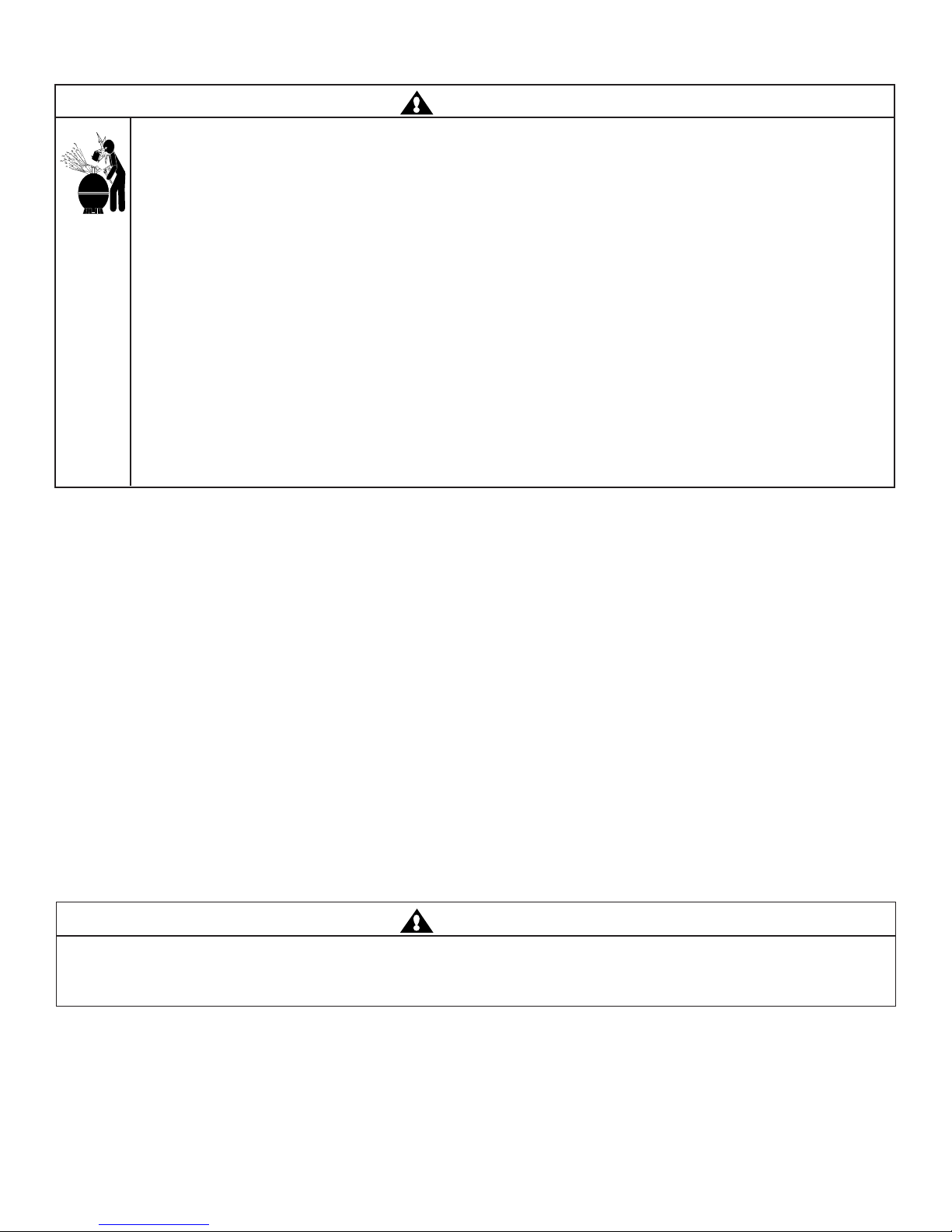
W ARNIN G
THIS FILTER OPERATES UNDER HIGH PRESSURE. WHEN AN
FILTER, VALVES, ETC.) IS SERVICED, AIR CAN ENTER THE SYSTEM AND
CAUS
E THE LID OR CONTROL VALVE TO BLOW OFF WHICH
D
AMAGE. TO AVOID THIS POTENTIAL HAZARD
, FOLLOW THES
Y PART OF THE CIRCUL
CAN RESULT IN SEVERE INJUR
E INSTRUCTION
ATING SYS
TEM (E.G., CLAMP, PUMP,
BECOME PRESSURIZED. PRESSURIZED AIR CA
Y, DEATH, OR PROPERTY
S
.
N
1. BEFORE REPOSITIONING VALVES AND
THE CLAMP OR ANY OTHER SER
ANY AUTOMATIC CONTROLS TO ENSUR
SER
VICING; (B) OPEN HIGH FLOW™ MANUAL
PRESSURE GAUGE MUST READ ZERO (0
2.
WHENEVER INSTALLING THE FILTER CLAMP, FOLLOW TH
BEFOR
E BEGINNING TH
VICE OF THE CIRCUL
E THE SYSTEM IS NO
AIR RELIEF VALVE; (C) WAIT UNTIL ALL PRESSUR
)
.
E ASSEMBLY, DISASSEMBLY, OR ADJUSTMENT OF
ATING SYS
TEM: (A) TURN THE PUMP OFF AND SHUT OFF
T INADVERTENTLY STARTED DURING THE
E FILTER LID AND CL
AMP INSTALL
E IS RELIEVE
ATION
INSTRUCTIONS EXACTLY.
3.ON
CE SERVICE ON TH
E CIRCUL
ATING SYS
TEM IS COMPLETE, FOLLOW SYS
TEM RESTART INSTRUCTION
EXACTLY.
4. MAINTAIN CIRCUL
CLAMP, PRESSURE GAUGE, RELIEF VALVE,
5. BE SURE THAT THE FILTER IS PROPERLY MOUNTED AND POS
PROVIDED
A. GENERAL INFORMATION - HOW YOUR FILTER WORKS.
1. Your high rate sand filter is designed to produce clear, sparkling water and operate for years with a minimum of maintenance
when installed, operated and maintained in accordance with these instructions:
Your filter uses special filter sand to remove dirt particles from the water. Dirt is collected in the filter by the sand bed as
water flows through the filter. Water enters the filter through the valve on top of the filter. It is then distributed evenly
downward, across and through the sand bed. The dirt is removed by the sand and the clean water flows through the piping
(laterals) at the bottom of the filter up through the center pipe back to the valve on top of the filter, where the clean water is
returned to the pool through the piping.
.
ATION SYS
TEM PROPERLY. REPLACE WORN OR DAMAGED PARTS IMMEDIATELY (E.
O-RINGS
, ETC.
)
.
ITIONED
ACCORDING TO INSTRU
CTION
S
D
,
S
G
.,
After a period of time, dirt will accumulate in the filter causing a resistance to the flow of water through the filter. This
resistance results in a diminished flow rate and a rise in the pressure of the filter. Eventually the filter sand will have removed
so much dirt and the filter pressure risen to such a point that it will be necessary to clean (backwash) your filter.
By setting the control valve on the top of the filter to the backwash position, the flow direction of water is reversed through
the filter so that the water is directed to the bottom of the filter and up through the sand bed flushing the dirt and debris out
through the waste line. Once the backwash procedure is complete, the valve must be returned to its filter position to resume
normal filtration.
The filter’s function is to remove suspended matter from the water and does not sanitize the water. For sparkling clear water
the water must be sanitized as well as chemically balanced. Pool chemistry is a specialized area and you should consult your
local pool service specialist for specific details. In general, proper pool sanitation requires a free chlorine level of 1 to 2 PPM
and a pH range of 7.2 to 7.6.
W ARNIN G
Failure to operate your filter system or inadequate filtration can cause poor water clarity obstructing visibility in your pool. POOR
W
ATER CLARITY MAY OBSCURE O
OF S
EVERE INJURY OR DEATH. NEVER SW
2. This filter operates under pressure. When clamped properly and operated without air in the water system, this filter will
operate in a safe manner.
3. The pressure gauge is the primary indicator of how the filter is operating. Maintain your pressure gauge in good working order.
BJECTS IN THE WATER WHICH
IM IN A POOL WITH
POOR W
MAY EXPOSE SWIMMERS OR DIVERS
ATER CLARITY.
TO THE RISK
Re v. C 5-11-01 3 P/N • Núm/Pt e. • Réf. 9910200 0
 Loading...