

Pentair ME40AC-21, ME40M-11, ME40P-1, ME40MC-21, ME40P-2 Owner's Manual
...
293 WRIGHT STREET, DELAVAN, WI 53115 WWW.FEMYERS.COM
PH: 888-987-8677
OWNER’S MANUAL
Submersible Effluent Pumps
ME40 / ME40AG Series
Installation/Operation/Repair Parts
For further operating, installation or
maintenance assistance:
Call 1-888-987-8677
© 2016 Pentair plc. All Rights Reserved. 23833A245 (10/26/16)
2
Important Safety Instructions
SAVE THESE INSTRUCTIONS - This manual contains
important instructions that should be followed during
installation, operation, and maintenance of the product.
Save this manual for future reference.
This is the safety alert symbol. When you see this
symbol on your pump or in this manual, look for one of
the following signal words and be alert to the potential
for personal injury!
indicates a hazard which, if not avoided, will
result in death or serious injury.
indicates a hazard which, if not avoided,
could result in death or serious injury.
indicates a hazard which, if not avoided,
could result in minor or moderate injury.
NOTICE addresses practices not related to
personalinjury.
Keep safety labels in good condition. Replace missing or
damaged safety labels.
1. Read these rules and instructions carefully. Failure to
follow them could cause serious bodily injury and/or
property damage.
2. Check your local codes before installing. You must
comply with their rules.
3. Vent sewage or septic tank according to local codes.
4. Do not install pump in any location classified as
hazardous by National Electrical Code, ANSI/NFPA
80-1984 or the Canadian Electrical Code.
Risk of electric shock. Can shock, burn
or kill. During operation the pump is in water.
To avoid fatal shocks, proceed as follows if pump
needsservicing:
Do not smoke or use devices that can generate
sparks in a septic (gaseous) environment.
5A. Disconnect power to outlet box before
unpluggingpump.
5B. Take extreme care when changing fuses. Do not
stand in water or put your finger in the fuse socket.
5C. Do not modify the cord and plug. When using the
cord and plug, plug into a grounded outlet only.
When wiring to a system control, connect the pump
ground lead to the system ground.
6. Be sure that construction and access to septic sumps
conform with all OSHA requirements.
7. Risk of burns. Do not run the pump dry.
Dry running can overheat the pump, (causing burns
to anyone handling it) and will void the warranty.
8. Risk of burns. The pump normally runs
hot. To avoid burns when servicing pump, allow it to
cool for 20 minutes after shutdown before handling.
9. The pump is permanently lubricated. No oiling or
greasing is required in normal operation.
California Proposition 65 Warning
This product and related accessories contain
chemicals known to the State of California to cause
cancer, birth defects or other reproductive harm
When used in effluent dosing or S.T.E.P. applications,
the pump must be installed in a separate tank or
compartment at the discharge side of the septic tank.
NOTICE Never install the pump in the main tank where
sludge collects. Do not use the pump for raw sewage.
Description
Myers ME40 Series Pumps are single seal units,
automatic or manual, designed for use in effluent dosing,
Septic Tank Effluent Pumping (S.T.E.P.) or normal sump
and general dewatering applications where higher
pressure is required. Impellers are enclosed two-vane
type to handle 3/4” spherical solids and are made of
engineered thermoplastic. All pumps have a 1-1/2” NPT
discharge tapping. Each pump is packaged separately
in a carton marked with a catalog number and Myers
engineering number.
NOTICE Do not overtighten discharge pipe into pump
plastic discharge fitting.
NOTICE This unit is not designed for applications
involving salt water or brine! Use with salt water or brine
will void warranty.
NOTICE This pump is not approved for, and should not
be used in, swimming pools orfountains.
ME40
The ME40 Series pumps are available in 115 volt or
230volt, single phase, 4/10 HP motors. All units are
single seal only, available in automatic or manual with
either 10’ or 20’ power cords. All power cords have
either 115volt or 230volt grounded plugs.
ME40AG
The ME40AG Series pumps are single seal units designed
for use in continuous run agricultural evaporative cooling
applications. They will run continuously in elevated
temperatures with clean sump water.
The wetted pump components are the same as already
described for the ME40 series.
Specifications
Model HP Volts Ph Cord Lgth. Type
ME40A-11
4/10
115
1
10’
Auto
ME40M-11 Manual
ME40AC-11
20’
Auto
ME40MC-11 Manual
ME40AC-21
230
Auto
ME40MC-21 Manual
ME40P-1
115
10’
Auto
ME40PC-1 20’
ME40P-2
230
10’
ME40PC-2
20’ME40AG-11 115
Manual
ME40AG-21 230
3
Motor Type
The motors used in the ME40/ME40AG pumps are
pressed into the cast iron housing and surrounded by
dielectric oil for the greatest heat dissipation. The ME40
uses a shaded pole, 4/10HP, 1550RPM motor. The
ME40AG uses a permanent split capacitor, 4/10HP,
1625RPM motor. Both units have Class A motor
insulation, are available in single phase 115 or 230volt
with overload protection, and use a lower ball bearing
- upper sleeve bearing. These pumps have no starting
switches and do not require a control panel for simplex
installation. All pumps have UL and CSA approval. Myers
is a SSPMA-certified pump member.
Air Locking
A sump pump is said to be air locked if air is trapped
in the pump and it cannot get out, thus preventing the
pump from operating.
The ME40/ME40AG pumps have a built-in air vent
hole in the impeller chamber to let out trapped air.
It is normal for liquid to spray out of this hole during
operation. If this hole becomes plugged, the pump may
air lock. As a secondary precaution a 1/8” hole should
be drilled in the discharge pipe below the check valve.
The check valve should be 12to18 inches above pump
discharge. Do not put check valve directly into pump
dischargeopening.
Level Controls
All pumps must use sealed level control switches for
automatic operation. All automatic pumps have built-in
level control float switches. The power cord has a ground
pin that plugs into a grounded receptacle. The grounded
receptacle cannot be used in the wet sump or basin due
to danger of current leakage.
Manual pumps can be made automatic with MLC
or MFLC controls with a series plug. Plug the MLC
or MFLC series plug into a proper voltage grounded
receptacle. Then plug the pump cord plug into the back
of the switch cord series plug. The float control must
be tethered a minimum 4” to pump or discharge pipe.
Control must float free from pump and basin wall.
On all duplex units or simplex installations with
additional options like high water alarm, the power cord
plug must be cut off and wired into a control panel or
into a sealed junction box if used in wet sump or basin.
The AWS-1 control also acts as a sealed junction box for
connecting power cord to pump cord.
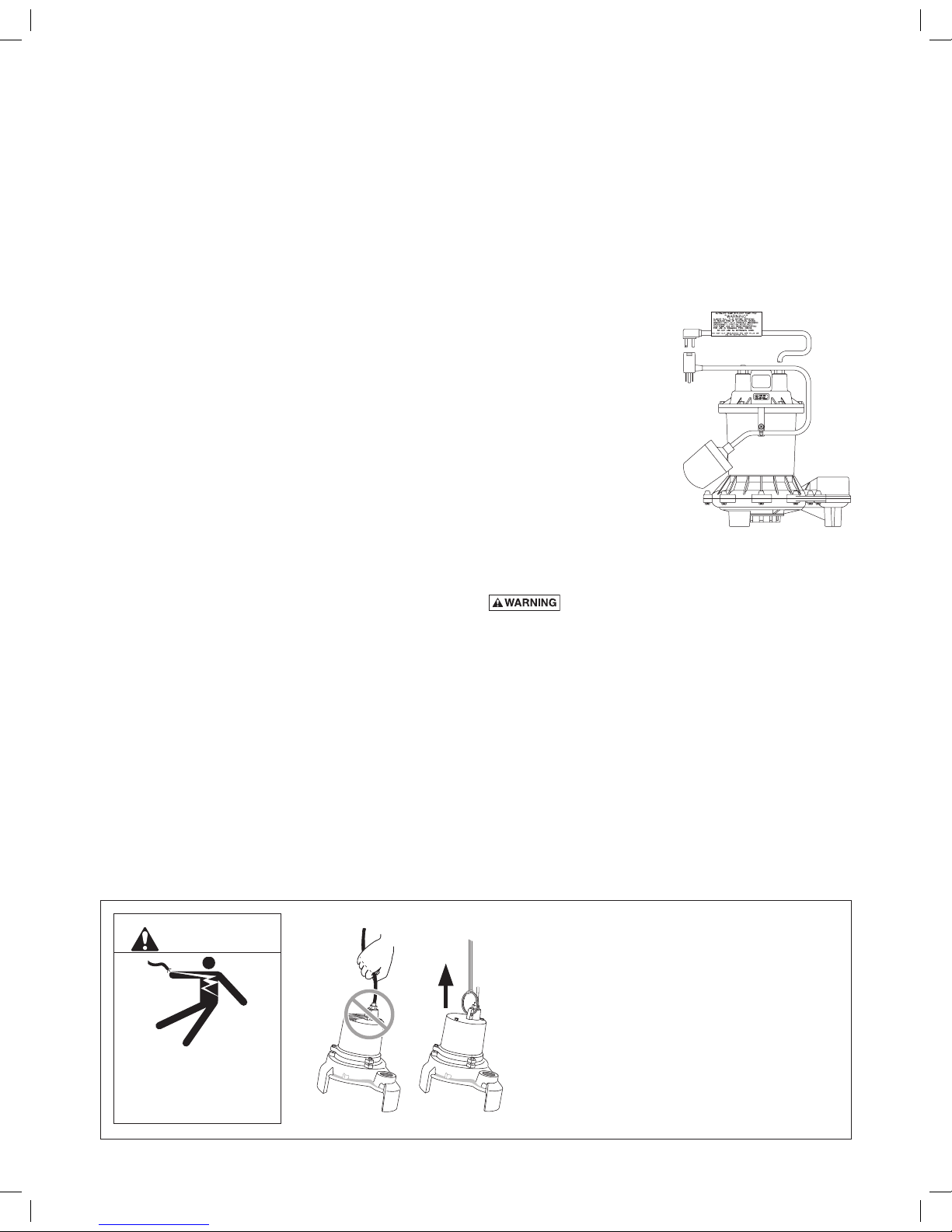
NOTICE The ME40 sump/effluent pump can be easily
changed from one style, automatic or manual, to the
other by merely interchanging the plug ends of the float
control with the manual plug. The ball float must be
tethered with a cable clamp, as shown. Do not remove
the motor cap.
ME40P pumps have a
mechanical (mercury free)
float switch with a 10’ or
20’ cord with a 115volt or
230volt piggyback plug with
the switch mounted to the
pump. Plug the switch cord
plug into a proper voltage,
properly grounded outlet
and plug the power cord into
the back of the switch cord
and tape the cords to the
discharge pipe every 12”.
Installation
Risk of electric shock. Can shock, burn or
kill. Do not lift pump by the power cord. See Cord Lift
Warning below.
NOTICE Install the pump on a hard, level surface
(cement, asphalt, etc.). Never place the pump directly on
earth, clay or gravel surfaces. Install the pump in a sump
basin with a minimum diameter of 18” (46cm).
1. Attempting to lift or support pump by power
cord can damage cord and cord connections.
2. Cord may pull apart, exposing bare wires with
possibility of fire or electrical shock.
3. Lifting or supporting pump by power cord will
void warranty.
4. Use lifting ring or handle on top of pump for
all lifting/lowering of pump. Disconnect power
to pump before doing any work on pump or
attempting to remove pump from sump.
Risk of electrical shock.
Can burn or kill.
Do not lift pump by power
cord.
WARNING
Cord Lift Warning
Typical pump shown
Piping
Piping must not be smaller than pump discharge.
The pump is designed to operate partially or completely
submerged in effluent liquids and pump semi-solid fluids
up to 3/4” (51mm) in diameter.
When installed in an effluent system, the pipe must be
capable of handling semi-solids of at least 3/4” (19mm)
in diameter.
The rate of flow in the discharge pipe must keep any
solids present in suspension in the fluid. To meet
minimum flow requirements (2 feet per second in the
discharge line), size the pipe as follows:
A Pipe Size Of: Will Handle a Flow Rate Of:
1-1/2” (38mm) 12 GPM
2” (51mm) 21 GPM
2-1/2” (64mm) 30 GPM
3” (76mm) 48 GPM
In an effluent system use a 1-1/2” (38mm) check valve in
pump discharge to prevent backflow of liquid into sump
basin. The check valve should be a free flow valve that
will easily pass solids. Be sure check valve installation
complies with local codes.
Be sure that the float switch hangs freely. It should not be
able to come in contact with the sides or bottom of the
sump pit.
Make sure the sump pit is free of any debris that could
obstruct the intake volute or switch.
Use plumbing materials that are approved by local
building codes when connecting pipes between pump
and sewer outlet.
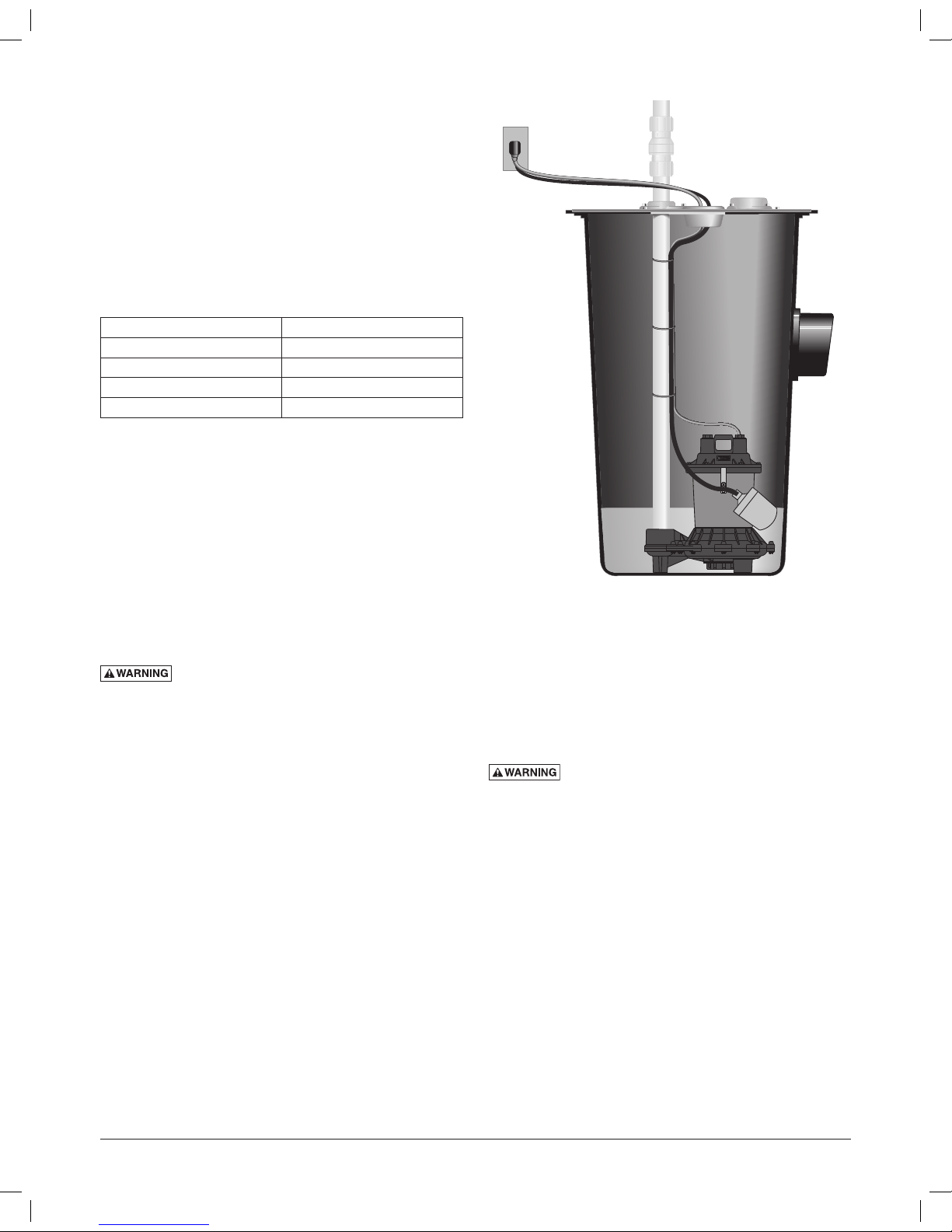
Risk of explosion and hazardous gas. Never
enter pump chamber after sewage or effluent has been
in basin. Sewage water can give off methane, hydrogen
sulfide, and other gasses which are highly poisonous. For
this reason, Myers recommends installing effluent pumps
with a quick removal system. The quick removal system
may be a union or quick-release coupling if the pipe or
discharge hose is within reach from the surface, or a rail
system type quick disconnect on deeper installations. See
Figure 2 for a typical installation.
The dosing tank or pumping chamber must be
constructed of corrosion resistant materials and must
be capable of withstanding all anticipated internal
and external loads. It also must not allow infiltration
or exfiltration. The tank must have provisions for antibuoyancy. Access holes or covers must be adequate
size and be accessible from the surface to allow for
installation and maintenance of the system. Access
covers must be lockable or heavy enough to prevent
easy access by unauthorized personnel. The pumping
chamber holding capacity should be selected to allow
for emergency conditions.
Test the pump installation by filling the sump basin with
enough water to activate the pump and repeat this cycle
until satisfied with pump operation.
NOTICE For critical indoor installations where additional
high water protection is desired, install an audible alarm
system in the sump pit. For outdoor installations, confer
with your distributor.
Connect the power cord to a 3-prong grounded
ACreceptacle.
Electrical
Risk of electric shock. Can shock, burn or
kill. When installing, operating, or servicing this pump,
follow the safety instructions listed below.
1. DO NOT splice the electrical power cord.
2. DO NOT allow the plug on the end of the electrical
cord to be submerged.
3. DO NOT use extension cords. They are a fire hazard
and can reduce voltage sufficiently to prevent
pumping and/or damage motor.
4. DO NOT handle or service the pump while it is
connected to the power supply.
5. DO NOT remove the grounding prong from the
plug or modify the plug. To protect against electrical
shock, the power cord is a three-wire conductor and
includes a 3-prong grounded plug. Plug the pump
into a 3-wire, grounded, grounding-type receptacle.
Connect the pump according to the NEC or CEC and
local codes.
6. DO NOT connect to GFCI outlet as premature
failure of motor could occur.
4
Figure 2: ME40 Typical Installation
 Loading...