

Pentair MDC33D1, MDC33V1, MDC33P1, MDC33PC1 20, MDC33PC1 30 Owner's Manual
...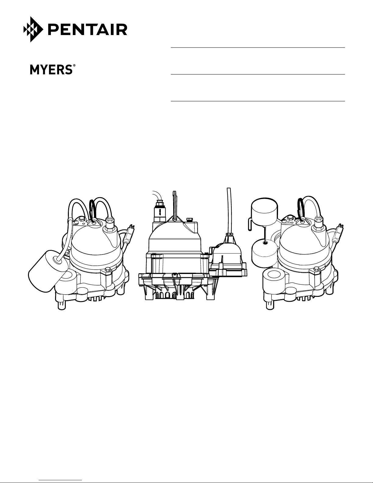
OWNER’S MANUAL
Submersible sump pumps
NOTICE D’UTILISATION
Pompe de puisard submersible
MANUAL DEL USUARIO
Bombas sumergible de sumidero
Installation/Operation/Parts
For further operating, installation,
or maintenance assistance:
Call 1-888-987-8677
English ...........Pages 2-8
293 WRIGHT STREET, DELAVAN, WI 53115 WWW.FEMYERS.COM
PH: 888-987-8677
© 2017 Pentair Ltd. All Rights Reserved.
MDC
Installation/Fonctionnement/Pièces
Pour plus de renseignements
concernant l’utilisation, l’installation
oul’entretien:
Composer le 1 (888) 987-8677
Français .........Pages 9-15
Instalación/Operación/Piezas
Para mayor información sobre
la operación, la instalación o
elmantenimiento:
Llame al 1-888-987-8677
Español .......Paginas 16-22
MY1048 (Rev. 09/28/17)

Safety 2
Important Safety Instructions
SAVE THESE INSTRUCTIONS - This manual contains
important instructions that should be followed during
installation, operation, and maintenance of the product.
Save this manual for future reference.
This is the safety alert symbol. When you see this
symbol on your pump or in this manual, look for one of
the following signal words and be alert to the potential
for personal injury!
indicates a hazard which, if not avoided, will
result in death or serious injury.
indicates a hazard which, if not avoided,
could result in death or serious injury.
indicates a hazard which, if not avoided,
could result in minor or moderate injury.
NOTICE
Carefully read and follow all safety instructions in this
manual and on pump.
Keep safety labels in good condition. Replace missing or
damaged safety labels.
addresses practices not related to personal injury.
Description
These submersible sump pumps are designed for home
sumps. The unit is equipped with a 3-prong groundingtype power cord. The shaded-pole motor is oil filled
and sealed for cooler running. Upper sleeve/lower ball
bearings on the motor shaft never need lubrication.
Automatic reset thermal protection.
General Safety Information
Electrically powered sump pumps normally give many
years of trouble-free service when correctly installed,
maintained, and used. However, unusual circumstances
(interruption of power to the pump, dirt/debris in the
sump, flooding that exceeds the pump’s capacity,
electrical or mechanical failure in the pump, etc.)
may prevent your pump from functioning normally. To
prevent possible water damage due to flooding, consult
your dealer about installing a secondary sump pump, a
DCbackup sump pump, and/or a high water alarm. See
Troubleshooting in this manual for information about
common sump pump problems and remedies. For more
information, see your dealer.
1. Know the pump application, limitations, and
potential hazards.
2. Disconnect the power before servicing.
3. Release all pressure within the system before
servicing any component.
4. Drain all water from the system before servicing.
5. Secure the discharge line before starting the pump.
An unsecured discharge line will whip, possibly
causing personal injury and/or property damage.
6. Check the hoses for a weak or worn condition before
each use. Make certain all connections are secure.
7. Periodically inspect the sump, pump and system
components. Keep free of debris and foreign objects.
Perform routine maintenance as required.
8. Provide a means of pressure relief for pumps whose
discharge line can be shut-off or obstructed.
9. Personal Safety:
a. Wear safety glasses at all times when working
with pumps.
b. Keep the work area clean, uncluttered and
properly lighted – replace all unused tools
andequipment.
c. Keep visitors at a safe distance from work area.
d. Make the workshop child-proof – with padlocks,
master switches, and by removing starter keys.
10. When wiring an electrically driven pump, follow all
electrical and safety codes that apply.
11. This equipment is only for use on 115 volt
(single phase) and is equipped with an approved
3-conductor cord and 3-prong, grounding-type plug.
or kill. To reduce risk of electric shock, pull plug
before servicing. Pump is supplied with a grounding
conductor and grounding-type attachment plug. Be
sure it is connected only to a properly grounded
grounding-type receptacle.
Where a 2-prong wall receptacle is encountered, it
must be replaced with a properly grounded 3-prong
receptacle installed in accordance with codes and
ordinances that apply.
This pump has not been investigated for use in
swimming pool areas.
12. All wiring should be performed by a
qualifiedelectrician.
13. Make certain the power source conforms to the
requirements of your equipment.
14. Protect the electrical cord from sharp objects,
hot surfaces, oil, and chemicals. Avoid kinking
the cord. Replace or repair damaged or worn
cordsimmediately.
15. Do not touch an operating motor. Motors can
operate at high temperatures.
16. Do not handle the pump or pump motor with wet
hands or when standing on wet or damp surface, or
in water.
California Proposition 65 Warning
chemicals known to the State of California to cause
cancer, birth defects or other reproductive harm
Electrical shock hazard. Can burn
This product and related accessories contain
Specifications • Installation 3
Electrical shock hazard. Can burn or
kill. If your basement has water or moisture on
floor, do not walk on wet area until all power has
been turned off. If shut-off box is in basement, call
electric company or hydro authority to shut-off
service to house, or call your local fire department
for instructions. Remove pump and repair or re place.
Failure to follow this warning can result in fatal
electrical shock.
17. Pump water only with this pump. Do not use with
salt water or brine.
18. Do not install the pump in any location classified as
hazardous by the National Electric Code, ANSI/NFPA
70-1984 or the Canadian Electrical Code.
Specifications
Power supply required...................... 115V, 60 HZ.
Liquid Temp. Range................ 32°F to 130°F (0°-54°C)
Individual Branch MDC33 Series ...............15 Amps
Circuit Required: MDC50 Series ...............20 Amps
Discharge Adapter...........................1-1/2” NPT
Performance
GPM (LPM) at total feet (m)
Model 5 (1.5m) 10 (3) 15 (4.6) 20 (6.1) 25 (7.6)
Capacity gallons (liters)/minute
MDC33 48 (182) 40 (151) 29 (110) 15 (57) -
MDC50 62 (235) 53 (201) 46 (174) 38 (144) 29 (110)
No flow
at height
shown
below
24 ft.
(7.3m)
32 ft.
(9.8m)
Installation
1. Install the pump in a sump pit with a minimum
diameter of 10” (254 mm) for models equipped
with vertical switches, 12” (305 mm) for diaphragm
float switch models and 14” (356 mm) for tethered
tethered float switch models. The sump depth should
be 15” minimum (381mm). Construct the sump pit of
tile, concrete, steel or plastic. Check the local codes
for approved materials.
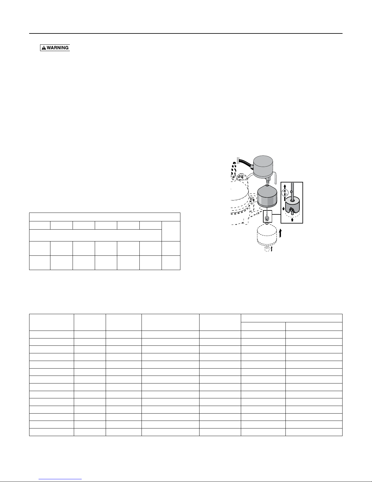
2. NOTICE: When installing the vertical switch, the
rod stop (Ref. No. 1F, Repair Parts) must not be
pushed up farther than the bottom nib on the float
rod. Pushing it any farther up the rod will cause the
switch to hang up on the pump discharge and will
damage thepump.
Figure 1
3. The pump should not be installed on clay, earth or
sand surfaces. Clean the sump pit of small stones
and gravel which could clog the pump. Keep the
pump inlet screen clear.
Motor, Switch, & Cord Specifications
Model Number Motor HP Full Load Amps
MDC33P1 1/3 9.8 15 10’ (3 m) 13” (330) 4” (102)
MDC33V1 1/3 9.8 15 10’ (3 m) 7” (178) 2” (51)
MDC33D1 1/3 9.8 15 10’ (3 m) 8 1/2” (216) 4” (102)
MDC33120V 1/3 9.8 15 20’ (6,1 m) 7” (178) 2” (51)
MDC33PC1 20 1/3 9.8 15 20’ (6,1 m) 13” (330) 4” (102)
MDC33PC1 30 1/3 9.8 15 30’ (9.1 m) 13” (330) 4” (102)
MDC33D1 20 1/3 9.8 15 20’ (6,1 m) 8 1/2” (216) 4” (102)
MDC50P1 1/2 12.5 20 10’ (3 m) 13” (330) 4” (102)
MDC50V1 1/2 12.5 20 10’ (3 m) 7” (178) 2” (51)
MDC50D1 1/2 12.5 20 10’ (3 m) 8 1/2” (216) 4” (102)
MDC5010M 1/2 12.5 20 20’ (6,1 m) – –
MDC50PC1 1/2 12.5 20 20’ (6,1 m) 13” (330) 4” (102)
MDC50VC1 1/2 12.5 20 20’ (6,1 m) 7” (178) 2” (51)
MDC50D1 20 1/2 12.5 20 20’ (6,1 m) 8 1/2” (216) 4” (102)
Individual Branch Circuit
Required (Amps)
Cord Length
Switch Setting in Inches (mm)
ON OFF
Installation • Operation / Maintenance 4
4. Install the pump in the pit so that the switch
mechanism has maximum possibleclearance.
5. Install the discharge plumbing. When using rigid
pipe, use plastic pipe. Wrap the threads with
PTFE tape. Screw the pipe into the pump hand
tight +1 – 1-1/2 turns.
NOTICE: Do not use ordinary pipe joint compound
on plastic pipe. Pipe joint compound can attack
plastics and damage the pump.
hose is used, make sure the pump is secure in
the sump to prevent movement. Failure to secure
the pump may allow pump movement, switch
interference and prevent the pump from starting
orstopping.
6. To reduce motor noise and vibrations, a short length
of rubber hose (e.g. radiator hose) can be connected
into the discharge line near the pump using
suitableclamps.
7. Install an in-line check valve to prevent backward
flow through the pump when the pump shuts off.
8. Power Supply: The pump is designed for 115V.,
60Hz., operation and requires a minimum
15amp (1/3 HP) or 20 amp (1/2 HP) individual
branch circuit (refer to Motor, Switch and Cord
Specifications). Both the pump and switch are
supplied with 3-wire cord sets with grounding-type
plugs. The switch plug is inserted directly into the
outlet and the pump plug inserts into the opposite
end of the switch plug.
or kill. The pump should always be electrically
grounded to a suitable electrical ground such as a
grounded water pipe or a properly grounded metallic
raceway, or ground wire system. Do not modify the
cord or plug or cut off the round ground pin.
9. If the pump discharge line is exposed to an outside
sub-freezing atmosphere, the portion of the line
exposed must be installed so any water remaining in
the pipe will drain to the outfall by gravity. Failure to
do this can cause the water trapped in the discharge
to freeze which could result in damage to the pump.
10. After the piping and check valve have been installed,
the unit is ready for operation.
11. Check the operation by filling the sump with
water and observing pump operation through one
complete cycle.
operational check may lead to improper operation,
premature failure, and flooding.
Risk of flooding. If a flexible discharge
Hazardous voltage. Can shock, burn
Risk of Flooding. Failure to make this
Operation / Maintenance
Risk of electrical shock. Can burn or cause
death. Do not handle a pump or pump motor with wet
hands or when standing on a wet or damp surface, or
inwater.
Before attempting to check why unit has stopped
operating, disconnect power from unit.
Risk of fire and explosion. Can cause
severe injury, property damage or death. Do not use in
explosive atmospheres. Pump water only with this pump.
1. The shaft seal depends on water for lubrication
and cooling. Do not operate the pump unless it is
submerged in water as the seal may be damaged if
allowed to run dry.
2. The motor is equipped with an automatic reset
thermal protector. If the temperature in the motor
should rise unduly, the switch will cut off all power
before damage can be done to the motor. When the
motor has cooled sufficiently, the switch will reset
automatically and restart the motor. If the protector
trips repeatedly, the pump should be removed and
checked as to cause of difficulty. Low voltage, long
extension cords, clogged impeller, very low head or
lift, etc., could cause cycling.
3. The pump will not remove all water. If a manually
operated pump is operating and suddenly no water
comes out of the discharge hose, shut the unit off
immediately. The water level is probably very low
and the unit has broken prime.
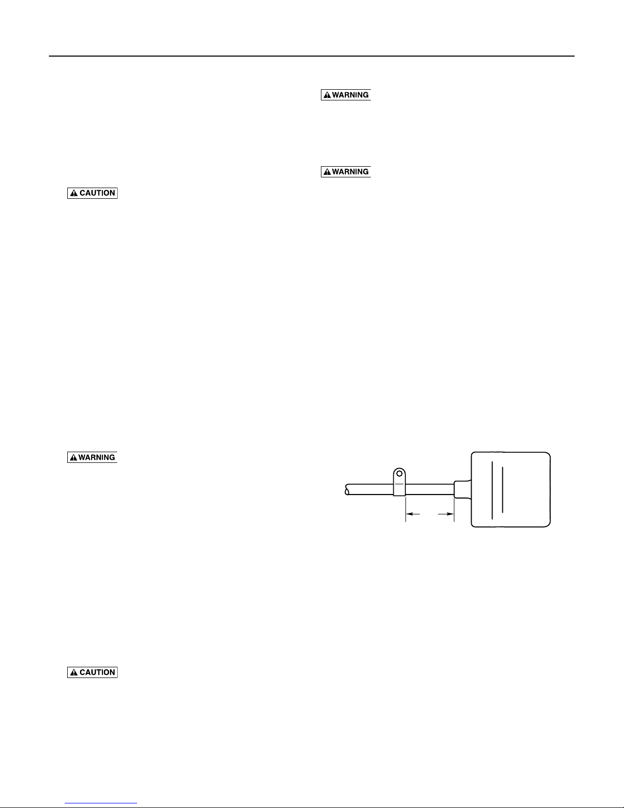
3-1/2"
(89 mm)
Figure 2 – Float Switch Tether Length, Models
MDC33P1, MDC33PC1, MDC50P1 and MDC50PC1.
NOTICE: Do not change the tether length of the float
switch. The float must be able to swing through its
complete arc without interference.
Airlocks
When a pump airlocks, it runs but does not move any
water. An airlock will cause the pump to overheat and
fail. These pumps have a built in anti-airlock hole. See
Repair Parts for the location of the hole. Leakage from
the anti-airlock hole is normal.
If you suspect an airlock, unplug the pump, clean out the
anti-airlock hole with a paper clip or a piece of wire, and
restart the pump.
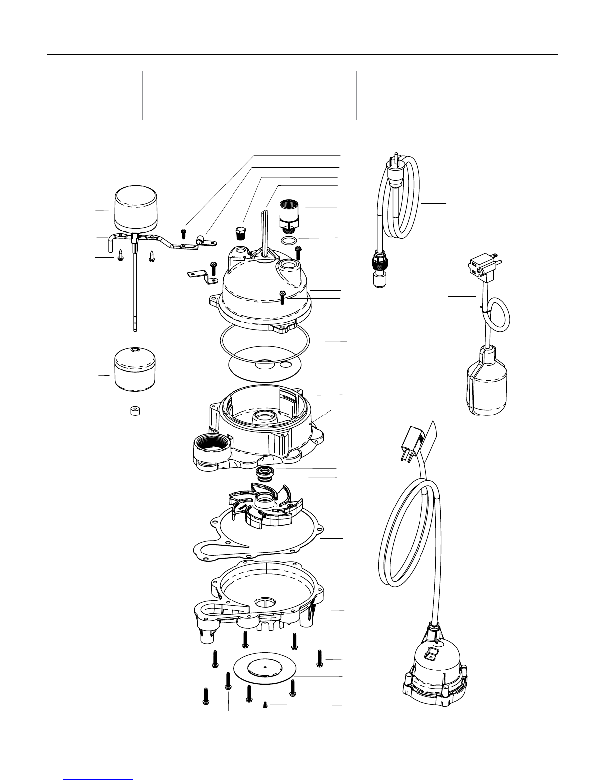
Repair Parts 5
MDC33P1
MDC33V1
MDC33D1
1A
1B
1C
1D
MDC33120V
MDC33PC1 20
MDC33PC1 30
23
MDC33D1 20
MDC50P1
MDC50V1
MDC5010M
2
3
4
5
6
6A
7
8
9
10
11
MDC50D1
MDC50M1
MDC50PC1
MDC50VC1
MDC50D1 20
20
21
1E
12A
12B
13
14
15
16
17
anti-airlock hole
22
18
19

Repair Parts 6
Ref. Description Qty.
1 Vertical Switch (Incl. 1A thru 1F) 1 – PKG 208 PKG 209 –
1A Switch 1
1B Mounting Bracket 1
1C Screw 2
1D Float 1
1E Retainer Strap 1
1F Stop 1
2 Screw, #8-1/2” self-tapping 1 U30-539SS –
3 Switch Cord Clamp 1 CC0030-13 –
4 Oil Fill Plug 1 U78-941ZPV
5 Ring Handle 1 U97-128
6 Cord Connector 1 PS17-46P
6A O-Ring 1 U9-370
7 Motor Cover 1 PS18-144GR
8 Capscrew, #10-32 x3/4” 3 U30-482SS
9 O-Ring 1 U9-339
10 Insulating Disk 1 PS18-82
11 Motor / Upper Volute 1 If the Motor fails, replace the entire pump.
Shaft Seal Stationary Head
12A
Assembly
12B Shaft Seal Rotating Mating Ring 1 U9-321A
13 Impeller 1
14 Gasket 1 PS20-21N
15 Lower Volute 1 PS1-34P
Lower Pump Body Screw #10-
16
32x1” Hex Washer, self-tapping
17 Suction Plate 1 U43-142SS
18 Screw, #6-1/4” pan head 1 U30-972SS
Lower Pump Body Screw
#10-32x1-1/8” Hex Washer,
19
self-tapping
20 Power Cord Assembly 1 See Power Cord Assembly Chart
21 Tethered Float Switch 1 PS17-109 PS17-111 –
Dielectric Oil All Models use .61 qts., U197-8A
22 Diaphragm Float Switch 1 – * **
Diaphragm Switch Mounting
23
Bracket
MDC33P1
MDC50P1
1 U9-379A
7 U30-966SS
1 U30-967SS
1 – U19-144SS
MDC33PC1 20
MDC33PC1 30
MDC50PC1
MDC33V1
MDC50V1
MDC33 Series pumps use Impeller number PS5-26P.
MDC50 Series pumps use Impeller number PS5-29P.
MDC33120V
MDC50VC1
MDC50M1 MDC5010M
MDC33D1 20
MDC50D1 20
MDC33D1
MDC50D1
Power Cord Assembly
Pump Model Number Part Number Pump Model Number Part Number
MDC33P1 PW117-281-TSU MDC50M1 PW117-237-TSU
MDC33V1 PW117-281-TSU MDC50P1 PW117-237-TSU
MDC33120V PW117-122-TSU MDC50V1 PW117-237-TSU
MDC33PC1 20/MDC33PC1 30 PW117-122-TSU MDC5010M PW117-122-TSU
MDC33D1 PW117-251-TSU MDC50PC1 PW117-122-TSU
MDC33D1 20 PW117-122-TSU MDC50VC1 PW117-122-TSU
MDC50D1 20 PW117-122-TSU MDCD1 PW117-237-TSU
*149740005-01 **149740015-01

Troubleshooting 7
Troubleshooting Chart
Symptom Probable Cause(s) Corrective Action
Blown fuse. If blown, replace with a fuse of proper size.
If the voltage is under the recommended minimum, check the size of the wiring
from the main switch on the property. If OK, contact power company or hydro
authority.
If the impeller won’t turn, remove the lower pump body and locate the source of
the binding.
If the voltage is under the recommended minimum, check the size of the wiring
from the main switch on the property. If OK, contact power company or hydro
authority.
Pump won’t start or run.
Pump starts and stops too often.
Pump won’t shut off.
Pump operates but delivers little
or no water.
Low line voltage.
Defective motor. Replace the pump.
Defective float switch. Replace the float switch.
Impeller.
Float is obstructed. Remove the obstruction.
Backflow of water from piping. Install or replace the check valve.
Faulty float switch. Replace the float switch.
Defective float switch. Replace the float switch.
Restricted discharge (obstacle in piping). Remove the pump and clean the pump and piping.
Float obstructed. Remove the obstruction.
Low line voltage.
Something is caught in impeller. Clean out the impeller.
Anti-airlock hole is plugged. Turn off the pump, clean out the anti-airlock hole, and restart pump.

Warranty 8
Limited Warranty
Myers® warrants to the original consumer purchaser (“Purchaser” or “You”) of the products listed below, that they will be free from
defects in material and workmanship for the Warranty Period shown below.
Product
Jet pumps, small centrifugal pumps, submersible pumps and
relatedaccessories
Fibrewound Tanks 5 years from date of original installation
Steel Pressure Tanks 5 years from date of original installation
Sump/Sewage/Effluent Products
Battery Backup Units
MBSP-2, MBSP-2C
MBSP-3, MBSP-3C
Wastewater Solids Handling Pumps
Our warranty applies only where such products are used in compliance with the requirements of the applicable product catalog
and/or manuals. For additional information, please refer to the applicable standard limited warranty featured in the product
manual.
Our warranty will not apply to any product that, in our sole judgement, has been subject to negligence, misapplication, improper
installation, or improper maintenance. Without limiting the foregoing, operating a three phase motor with single phase power
through a phase converter will void the warranty. Note also that three phase motors must be protected by three-leg, ambient
compensated, extra-quick trip overload relays of the recommended size or the warranty is void.
Your only remedy, and MYERS’s only duty, is that MYERS repair or replace defective products (at MYERS’s choice). You must pay
all labor and shipping charges associated with this warranty and must request warranty service through the installing dealer as
soon as a problem is discovered. No request for service will be accepted if received after the Warranty Period has expired. This
warranty is not transferable.
MYERS SHALL NOT BE LIABLE FOR ANY CONSEQUENTIAL, INCIDENTAL, OR CONTINGENT DAMAGES WHATSOEVER.
THE FOREGOING LIMITED WARRANTIES ARE EXCLUSIVE AND IN LIEU OF ALL OTHER EXPRESS AND IMPLIED
WARRANTIES, INCLUDING BUT NOT LIMITED TO IMPLIED WARRANTIES OF MERCHANTABILITY AND FITNESS FOR
A PARTICULAR PURPOSE. THE FOREGOING LIMITED WARRANTIES SHALL NOT EXTEND BEYOND THE DURATION
PROVIDED HEREIN.
Some states do not allow the exclusion or limitation of incidental or consequential damages or limitations on the duration of an
implied warranty, so the above limitations or exclusions may not apply to You. This warranty gives You specific legal rights and
You may also have other rights which vary from state to state.
Warranty Period
whichever occurs first:
12 months from date of original installation,
or 18 months from date of manufacture
12 months from date of original installation,
or 36 months from date of manufacture
12 months from date of original installation,
or 18 months from date of manufacture
24 months from date of original installation,
or 30 months from date of manufacture
12 months from date of shipment from factory
or 18 months from date of manufacture
This Limited Warranty is effective April 1, 2014 and replaces all undated warranties and warranties dated before April 1, 2014.
F.E. MYERS
293 Wright Street, Delavan, WI 53115
Phone: 888-987-8677 • Fax: 800-426-9446 • www.femyers.com
In Canada: 490 Pinebush Road, Unit 4, Cambridge, Ontario N1T 0A5
Phone: 800-363-7867 • Fax: 888-606-5484
 Loading...