

Pentair McLean SPECTRACOOL N36 Instruction Manual

Protecting Electronics.
Pentair Equipment Protection
INSTRUCTION MANUAL
SPECTRACOOL™
Air Conditioner
N36
2100 Homan Way
Minneapolis, MN 55303 USA
+1.763.422.2211
+1.763.576.3200
PentairEquipmentProtection.com
Rev. K
© 2013 Pentair Equipment Protection
Exceeding Expectations.™
P/N 89068450
89074140

RECEIVING THE AIR CONDITIONER .........................................................................................................................................................................................................................................................................3
TABLE OF CONTENTS
HANDLING AND TESTING THE AIR CONDITIONER ............................................................................................................................................................................................................................................ 3
HOW TO READ MODEL NUMBERS ..........................................................................................................................................................................................................................................................................3
TECHNICAL INFORMATION........................................................................................................................................................................................................................................................................................ 4
Sequence of Operation ...................................................................................................................................................................................................................................................................................4
Heating ......................................................................................................................................................................................................................................................................................................4
Cooling ...................................................................................................................................................................................................................................................................................................... 4
Standard and Optional Component Operation ..................................................................................................................................................................................................................................... 4
Thermostat ..............................................................................................................................................................................................................................................................................................4
Remote Access Control (optional) ...................................................................................................................................................................................................................................................4
Head Pressure Control ......................................................................................................................................................................................................................................................................... 4
Contactor..................................................................................................................................................................................................................................................................................................5
Phase Monitor (N360X46GXXX only) .............................................................................................................................................................................................................................................5
460 V to 230 V Transformer (N360X46GXXX only) .....................................................................................................................................................................................................................5
115/230 V to 10 V Transformer (optional) .....................................................................................................................................................................................................................................5
115/230 V to 24 V Transformer and Relay (optional) ................................................................................................................................................................................................................ 5
Schematics and Wiring Diagrams for Thermostat Control .................................................................................................................................................................................................................6
N36 1-Phase Generic Schematic (actual unit options may vary) .........................................................................................................................................................................................6
N36 3-Phase Generic Schematic (actual unit options may vary) .........................................................................................................................................................................................6
N36 1-Phase Generic Wire Diagram (actual unit options may vary) ................................................................................................................................................................................... 7
DIMENSIONAL DRAWINGS ........................................................................................................................................................................................................................................................................................ 9
INSTALLATION INSTRUCTIONS ...............................................................................................................................................................................................................................................................................10
REMOTE ACCESS CONTROL (optional) ................................................................................................................................................................................................................................................................11
DIMENSIONAL DRAWINGS ......................................................................................................................................................................................................................................................................................20
INSTALLATION INSTRUCTIONS WITH REMOTE ACCESS CONTROL ............................................................................................................................................................................................................21
MAINTENANCE ............................................................................................................................................................................................................................................................................................................22
SERVICE DATA...............................................................................................................................................................................................................................................................................................................27
TROUBLE SHOOTING .................................................................................................................................................................................................................................................................................................34
WARRANTY ...................................................................................................................................................................................................................................................................................................................38
RETURN AND REPAIR POLICY .................................................................................................................................................................................................................................................................................38
LIMITATION OF LIABILITY .........................................................................................................................................................................................................................................................................................39
N36 3-Phase Generic Wire Diagram (actual unit options may vary) ................................................................................................................................................................................... 8
With Thermostats ..............................................................................................................................................................................................................................................................................................9
INTRODUCTION ...............................................................................................................................................................................................................................................................................................11
ENERGIZING THE CONTROLLER .................................................................................................................................................................................................................................................................11
CONTROL STATUS INDICATION ..................................................................................................................................................................................................................................................................11
DISPLAYING AND CHANGING PROGRAM VARIABLES ........................................................................................................................................................................................................................12
OPERATING PARAMETERS ............................................................................................................................................................................................................................................................................12
ALARM PARAMETERS .....................................................................................................................................................................................................................................................................................12
DISPLAYING TEMPERATURE SENSOR #2 ..................................................................................................................................................................................................................................................12
COMPRESSOR RESTART TIME DELAY ........................................................................................................................................................................................................................................................12
ALARM OUTPUT CONTACT ..........................................................................................................................................................................................................................................................................12
ALARM INPUT CONNECTION ......................................................................................................................................................................................................................................................................12
ALARM CONDITION DISPLAY ......................................................................................................................................................................................................................................................................13
AIR CONDITIONER UNIT COMMUNICATION FEATURES .....................................................................................................................................................................................................................13
USB Communication ..........................................................................................................................................................................................................................................................................13
Ethernet Communication .................................................................................................................................................................................................................................................................13
Software and MIB File Downloads ................................................................................................................................................................................................................................................13
Using the McLean PC Interface Tool .............................................................................................................................................................................................................................................13
USB COMMUNICATION MODE ...................................................................................................................................................................................................................................................................14
Viewing Air Conditioner Unit Values ............................................................................................................................................................................................................................................14
Changing Air Conditioner Unit Values .........................................................................................................................................................................................................................................14
Viewing and Changing Ethernet Information ...........................................................................................................................................................................................................................14
ETHERNET COMMUNICATION MODE .......................................................................................................................................................................................................................................................15
Viewing Air Conditioner Unit Values ............................................................................................................................................................................................................................................15
Changing Air Conditioner Unit Values .........................................................................................................................................................................................................................................15
Viewing and Changing Ethernet Information ...........................................................................................................................................................................................................................15
Alarm Log Accessible with SNMP ..................................................................................................................................................................................................................................................15
Remote Access Control Pin-out .................................................................................................................................................................................................................................................................16
Schematic and Wiring Diagram for Remote Access Control ...........................................................................................................................................................................................................17
N36 1-Phase Generic Schematic (actual unit options may vary) .......................................................................................................................................................................................17
N36 3-Phase Generic Schematic (actual unit options may vary) .......................................................................................................................................................................................17
N36 1-Phase Generic Wire Diagram for Remote Access Control (actual unit options may vary) ...........................................................................................................................18
N36 1-Phase Generic Wire Diagram for Remote Access Control (actual unit options may vary) ...........................................................................................................................19
N36 Generic Model Drawing With Remote Access Control .............................................................................................................................................................................................................20
Compressor .......................................................................................................................................................................................................................................................................................................22
Inlet Air Filter ....................................................................................................................................................................................................................................................................................................22
How To Remove, Clean or Install a New Inlet Air Filter ......................................................................................................................................................................................................................22
Condenser and Evaporator Air Movers ...................................................................................................................................................................................................................................................23
Refrigerant Loss ...............................................................................................................................................................................................................................................................................................23
Refrigerant Properties Chart (R 134a) ......................................................................................................................................................................................................................................................24
Functional Data ...............................................................................................................................................................................................................................................................................................24
6000 BTU/Hr. Unit Characteristics .............................................................................................................................................................................................................................................................25
8000 BTU/Hr. Unit Characteristics .............................................................................................................................................................................................................................................................26
6000 BTU/Hr. Components List ..................................................................................................................................................................................................................................................................27
8000 BTU/Hr. Components List ..................................................................................................................................................................................................................................................................27
Controller Components List ........................................................................................................................................................................................................................................................................28
N36-0616-GXXX Pressure Tables ...............................................................................................................................................................................................................................................................28
N36-0626-GXXX Pressure Tables ...............................................................................................................................................................................................................................................................29
N36-0646-GXXX Pressure Tables ...............................................................................................................................................................................................................................................................30
N36-0816-GXXX Pressure Tables ...............................................................................................................................................................................................................................................................31
N36-0826-GXXX Pressure Tables ...............................................................................................................................................................................................................................................................32
N36-0846-GXXX Pressure Tables ...............................................................................................................................................................................................................................................................33
Basic Air Conditioning Trouble Shooting Check List - Thermostat Version................................................................................................................................................................................34
Symptoms and Possible Causes - Thermostat Version ......................................................................................................................................................................................................................35
Basic Air Conditioning Trouble Shooting Check List - Remote Access Control Version ........................................................................................................................................................36
Symptoms and Possible Causes - Remote Access Control Version ...............................................................................................................................................................................................37
- 2 -
© 2013 Pentair Equipment Protection
89074140
RECEIVING THE AIR CONDITIONER
Inspect the air conditioner. Check for concealed damage that may have occurred during shipment. Look for dents,
scratches, loose assemblies, evidence of oil, etc. Damage evident upon receipt should be noted on the freight bill.
Damage should be brought to the attention of the delivering carrier -- NOT to Pentair Equipment Protection -- within
15 days of delivery. Save the carton and packing material and request an inspection. Then le a claim with the
delivering carrier.
Pentair Equipment Protection cannot accept responsibility for freight damages; however, we will assist you in any way
possible.
HANDLING AND TESTING THE AIR CONDITIONER
If the air conditioner has been in a horizontal position, be certain it is placed in an upright, vertical or mounting
position for a minimum of ve (5) minutes before operating.
CAUTION
Do not attempt to operate the air conditioner while it is horizontal
or on its side, back or front. The refrigeration compressor is lled
with lubricating oil. This will cause permanent damage to the air
conditioner and also voids the warranty.
TEST FOR FUNCTIONALITY BEFORE MOUNTING THE AIR CONDITIONER TO THE ENCLOSURE.
Refer to the nameplate for proper electrical current requirements, and then wire the unit to a properly grounded
power supply using copper conductors only. Power supply wiring should be restrained after eld installation to ensure
no contact with internal fan. Minimum circuit ampacity should be at least 125% of the amperage shown on the unit
nameplate. No other equipment should be connected to this circuit to prevent overloading
Immediately after applying power, the evaporator blower (enclosure air) should start running. Operate the air
conditioner with the compressor running for ve (5) to ten (10) minutes. You will need to set the cooling thermostat or
controller setpoint below the ambient temperature to operate the compressor.
Condenser air temperatures should be warmer than normal room temperatures within a few minutes after the
condenser impellers start.
See Sequence of Operation on page 4 for specics on how the unit operates when powered up.
HOW TO READ MODEL NUMBERS
N36 06 2 6 G150
1 2 3 4 5
1. Identies the type/family of air conditioner and the approximate height (i.e. N36 = Global family about 36
inch high).
2. This is the air conditioner’s listed capacity in BTU/Hr. at rated conditions. (i.e. 06 = 6,000 BTU/Hr. at 131/131 F)
3. 1 = 115 Volt, 2 = 230 Volt, 4 = 460 Volt.
4. 6 = 50/60 Hz or 60 Hz only.
5. Unique set of numbers for each air conditioner which identies the accessories on a model.
© 2013 Pentair Equipment Protection89074140 - 3 -

TECHNICAL INFORMATION
Sequence of Operation
The air conditioner comes standard with two internally mounted thermostats. There are two modes of operation;
heating and cooling. During heating and cooling modes, the evaporator fan will be running.
Heating
When the enclosure temperature is below the heating thermostat setpoint, power is applied to the heaters.
When the enclosure temperature is 10 degrees above the setpoint, the heater is powered o.
Cooling
When the enclosure temperature is above the cooling thermostat setpoint, power is applied through the
thermostat. The compressor is then energized either directly or through a contactor if unit requires one. The
condenser impellers will start immediately if the unit is not equipped with an optional head pressure control
switch. If the unit is equipped with an optional head pressure control switch, the condenser impellers will
start once the refrigerant pressure reaches the setting of the switch. Component specic information is listed
below.
Operating the air conditioner below the minimum ambient temperature or above the maximum ambient
temperatures indicated on the nameplate voids all warranties. DO NOT set the enclosure thermostat to a
temperature lower than 70 F. Doing so can increase the likelihood of frost buildup on the evaporator coil.
The moisture that the enclosure air can contain is limited. If moisture ows from the drain tube continuously
this can only mean that ambient air is entering the enclosure. Be aware that frequent opening of the
enclosure’s door admits humid air that the air conditioner must then dehumidify.
Standard and Optional Component Operation
Thermostat
The G52 air conditioner uses our standard 10-1061-16 thermostat. The thermostat setpoint equals the
temperature that the air conditioner turns o. The thermostat has a 10 F dierential from setpoint until it calls
for cooling or heating. An example of operation is shown below.
For cooling (75-100 F range):
• Thermostat setpoint = 80 F
• Cooling turns on at 90 F
• Cooling turns o at 80 F
For heating (55-65 F range):
• Thermostat setpoint = 55 F
• Heating turns on at 55 F
• Heating turns o at 65 F
NOTE: For testing purposes only, the thermostat stop screw may be removed (on units so
equipped) to allow settings below 70 F. After testing, replace the stop screw and verify that the
thermostat cannot be set below 70 F. Extended operation below 70 F can cause coil freeze ups
resulting in reduced load and/or unit damage.
Remote Access Control (optional)
See REMOTE ACCESS CONTROL (optional) on page 11
Head Pressure Control
Unit is set at the factory, no adjustment necessary.
At a saturated condenser temperature of 85 F (95 psig), the condenser fans will power o. At a saturated
condenser temperature of 118 F (165 psig), the condenser fans will power on.
- 4 -
© 2013 Pentair Equipment Protection
89074140

Contactor
The contactor on the 1-phase 115V model uses a 115V coil (controller option only).
The contactor on the 1-phase 230V model uses a 230V coil (controller option only).
The contactor on the 3-phase model uses a 230V coil (controller option only).
Phase Monitor (N360X46GXXX only)
The phase monitor protects the compressor from reverse operation. When both lights on the monitor are lit
constant, the power to the unit has been wired correctly and the compressor will operate as designed.
If both lights on the monitor are not on constant, swap the power leads at the terminal block until both lights
are on constant.
Factory Settings:
Top dial set at 480 V for 60 Hz operation (Reset to 440 V for 50 Hz operation)
Middle dial set at 5 seconds
Bottom dial set at -20%
460 V to 230 V Transformer (N360X46GXXX only)
The 230 V from this transformer powers the fans, contactor and optional transformers. 460 V is only used to
run the compressor.
115/230 V to 10 V Transformer (optional)
This transformer powers the temperature display only.
115/230 V to 24 V Transformer and Relay (optional)
This transformer and relay are used to start/stop the unit by using a customer supplied, remote mounted door
switch.
© 2013 Pentair Equipment Protection89074140 - 5 -

Schematics and Wiring Diagrams for Thermostat Control
6
$
6
5
5
5
2
6
$
:
2
2
N36 1-Phase Generic Schematic (actual unit options may vary)
88026037
N36 3-Phase Generic Schematic (actual unit options may vary)
/ /6/
3+$6(
021,725
&,5&8,7
%5($.(5
*51'
5
&217$&725
7
9$5,6725
$87275$16)250(5
+3&
075
&$3
075
75$16)
7(03',
237,21
&2035(
7+(502
3+$6(
021,72
5(/$<
'2256
75$16)
5(/$<
(9$325
,03(//(
&21'(1
,03(//(
&2035(6625
- 6 -
075
&$3
© 2013 Pentair Equipment Protection
89062969
89074140

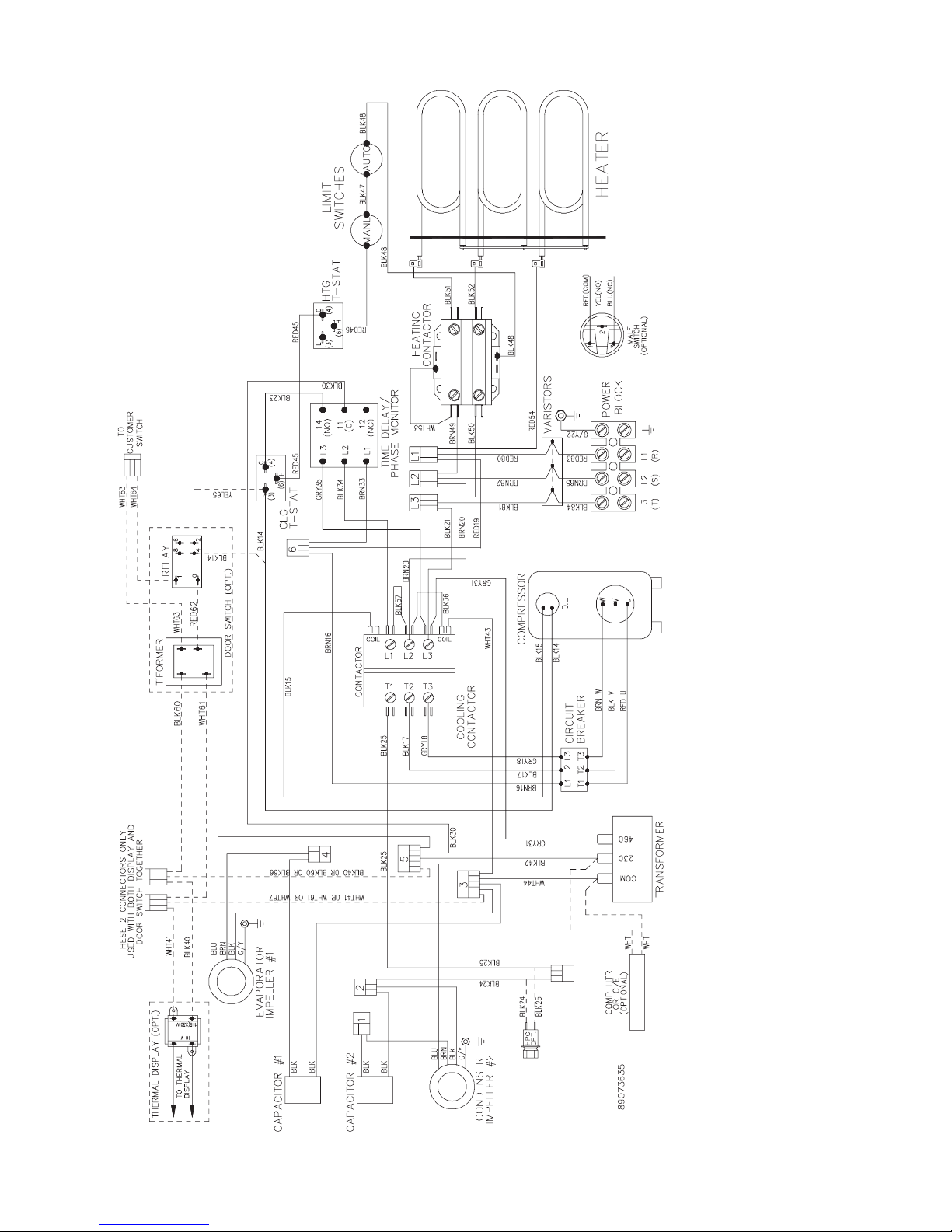
N36 1-Phase Generic Wire Diagram (actual unit options may vary)
TO
CUSTOMER
SWITCH
WHT61
BLK60
HEATER
ENCLOSURE
IMPELLER
#1
GRN/YEL
4
HEATING
T-STAT
BLK
BLU
BRN
T'FORMER
DOOR SWITCH (OPT.)
RED30
6
3
4
BRN26
BLK27
BLK28
WHT63
RED62
4
LIMIT
SWITCHES
WHT64
6
COOLING
T-STAT
RELAY
1
0
3
BLU29
482
YEL65
YEL10 OR
YEL65
RED13
BLK
BLK
BLK
BLK
GRN/YEL21
POWER
BLOCK
6
YEL10
3
YEL10
BLK11
BLK14
BRN8
RED13
BLK12
BLU19
5
BLU9
WHT7
WHT41
BLK40
SUPPRESSOR
(OPTIONAL)
BLK11
THERMAL DISPLAY (OPT.)
10 V
115(230) V
25
1
START
RELAY
WHT61
YEL4
TO THERMAL
DISPLAY
ORG6
RED5
WHT7
RED(COM)
1
MALF
SWITCH
(OPTIONAL)
START
CAP.
RED R
RUN
CAP.
YEL(NO)
BLU(NC)
2
3
BLK12
1
89073634
AMBIENT
IMPELLER
#2
ENC.
AMB.
BLK
BLU
BRN
GRN/YEL
BLK20
BLK1
2
C
S
YEL S
R
BLK 115V / WHT 230V
© 2013 Pentair Equipment Protection89074140 - 7 -
BLK 115V / WHT 230V
COMPRESSOR
RED R
COMP HTR
OR C/E
(OPTIONAL)
BLK20
(OPTIONAL)
BLK12
HPC
N36 3-Phase Generic Wire Diagram (actual unit options may vary)
- 8 -
© 2013 Pentair Equipment Protection
89074140
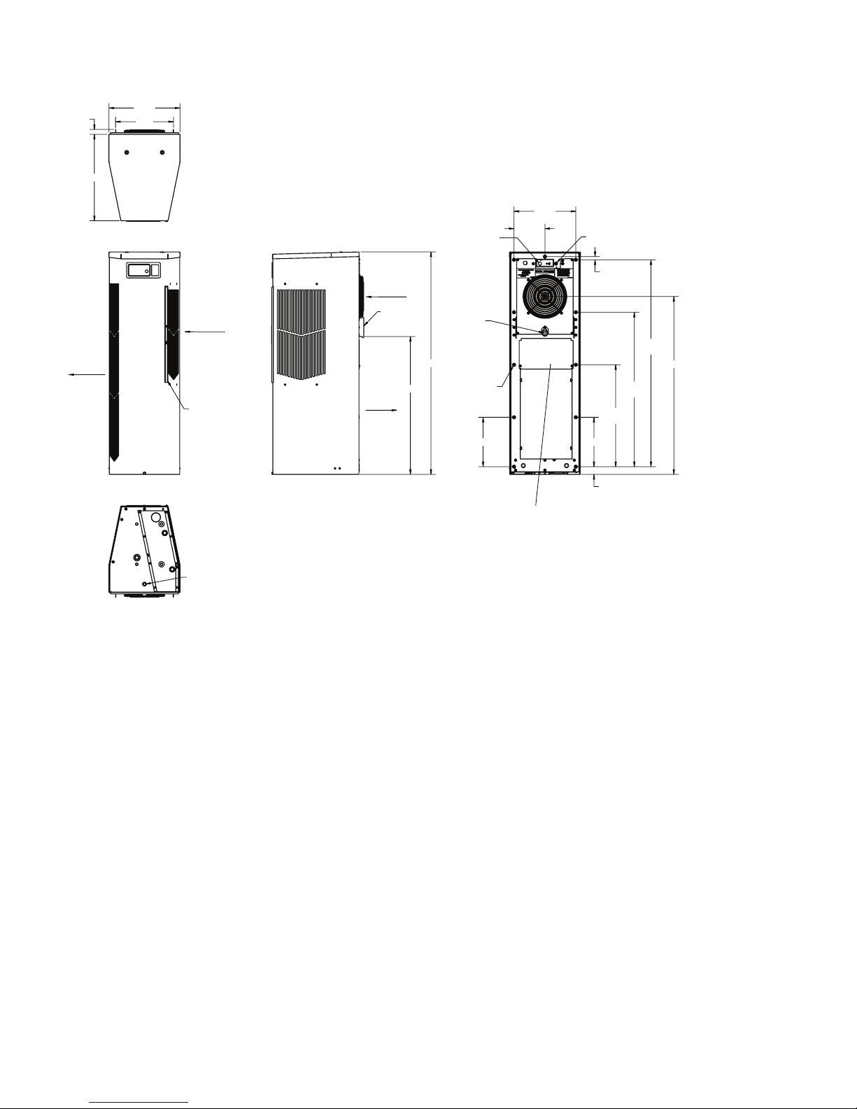
DIMENSIONAL DRAWINGS
With Thermostats
:$50
$,5287
$0%,(17
$,5,1
&/($1$%/(5(86$%/(
$/80,180,1/(7),/7(5
38//6287)5217
&22/
$,5287
(1&/65
$,5,1
5(029$%/(
+$1*,1*
7$%6
+($7767$7
237,21$/
32:(5
,1387
;81&
07*+2/(6
&22/767$7
;
$
;
;
89068455
$&&(66+2/(72
2''5$,1678%
237,21$/$&&(663$1(/
21/<)2581,76:,7++($7(5
;
© 2013 Pentair Equipment Protection89074140 - 9 -
INSTALLATION INSTRUCTIONS
1. Inspect the air conditioner and verify correct functionality before mounting the air conditioner. See
HANDLING AND TESTING THE AIR CONDITIONER on page 3.
2. Using the mounting gasket kit provided with the unit, install gaskets to the air conditioner, see Figure 1.
3. Mount air conditioner on enclosure taking care not to damage the mounting gasket. The mounting gasket is
the seal between the air conditioner and the enclosure. Avoid dragging the air conditioner on the enclosure
with the mounting gasket attached as this could cause rips or tears in the gasket and risk losing the water
tight seal.
4. Allow unit to remain upright for a minimum of ve (5) minutes before starting. CAUTION! Air conditioner
must be in upright position during operation.
5. Refer to the nameplate for electrical requirements. Wire the unit to a properly grounded power supply.
Electrical circuit should be fused with slow blow or HACR circuit breaker.
6. Some air conditioners require a remote mounted thermostat. Wire the thermostat outputs to the
appropriate terminals on the 24 VAC terminal strip by noting the locations on the correct wiring diagram.
7. Set thermostat for required cabinet temperature. Refer to Sequence of Operation on page 9 for thermostat
adjustment and operation.
89074387
- 10 -
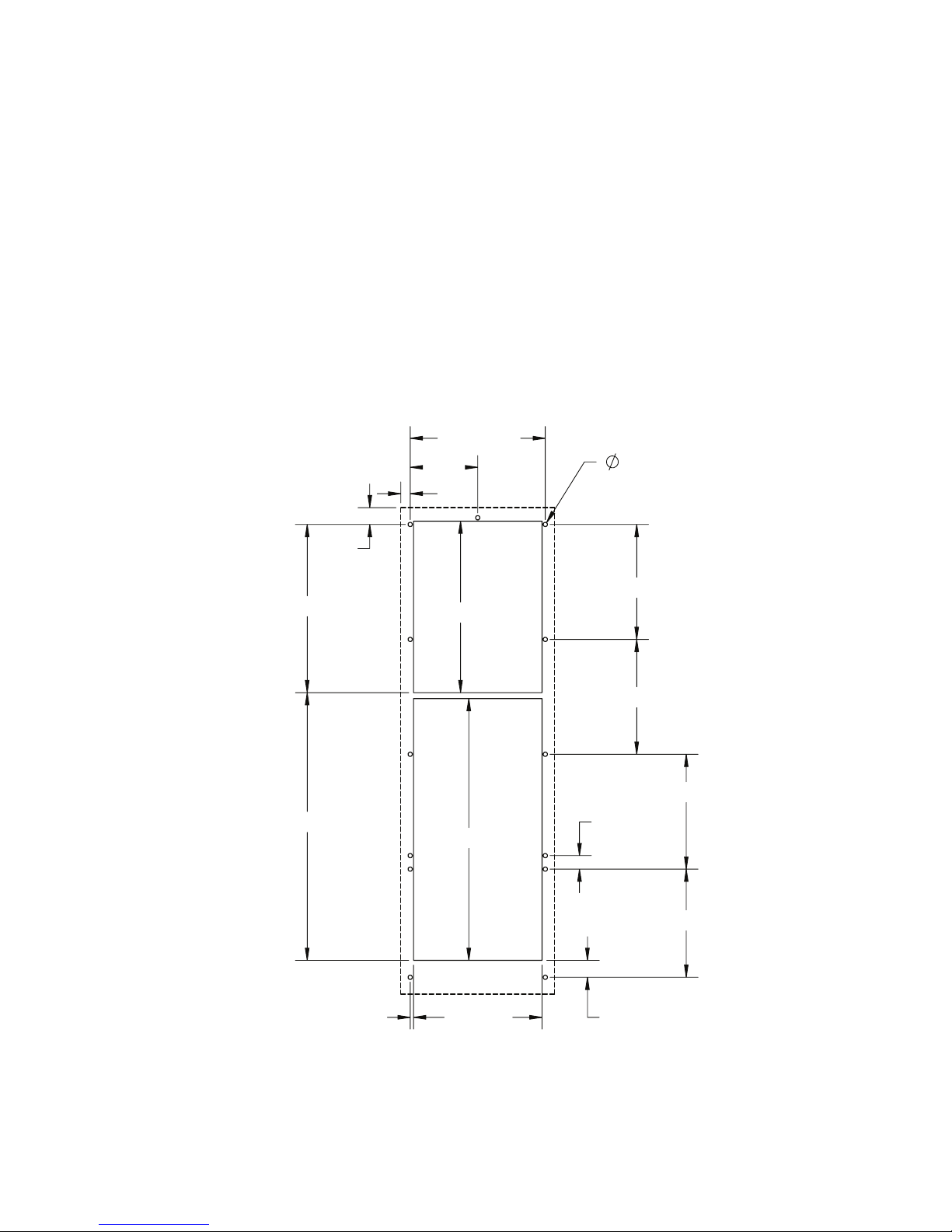
SURFACE MOUNT
Figure 1
Cutout Dimensions
© 2013 Pentair Equipment Protection
89074140
REMOTE ACCESS CONTROL (optional)
INTRODUCTION
The McLean Remote Access Control is a parametric controller for the complete management of McLean air
conditioners. All settings are pre-programmed at the factory. Cooling/heating set-points, cooling/heating dierential
and high /low temperature alarm set-points can be adjusted by the user. Alarms are outputted through a relay contact
and also can be accessed through an Ethernet connection utilizing SNMP. A USB connection is also provided and can
be used to interface with the controller utilizing ModBus.
ENERGIZING THE CONTROLLER
The controller is wired and programmed at the factory to be energized when power is supplied to the air conditioner.
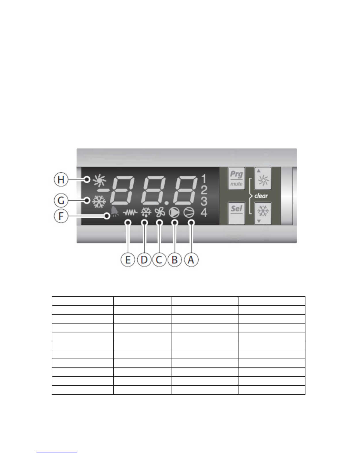
CONTROL STATUS INDICATION
The display has numerous symbols that indicate if the controller is heating, cooling, alarming, if the compressor is
enabled, and if the ambient fan is enabled. The 3 alpha-numeric characters further describe alarms and show the
cabinet temperature by default.
SYMBOL COLOR ICON ON ICON FLASHING
1 AMBER Compressor On Start-up Request
2,3,4 AMBER Not Used Not Used
A AMBER Compressor On Not Used
B AMBER Evaporator Fan On Start-up Request
C AMBER Not Used Not Used
D AMBER Not Used Not Used
E AMBER Heater Active Not Used
F RED Alarm Active Not Used
G AMBER Controller Active Not Used
H AMBER Not Used Not Used
© 2013 Pentair Equipment Protection89074140 - 11 -

DISPLAYING AND CHANGING PROGRAM VARIABLES
Access: To view and/or change parameters, press and hold the Prg and Sel buttons for greater than 5 seconds. Press
the up or down arrow buttons until “22” is displayed, then press Sel button. When “S-P” is displayed, press Sel.
Navigation: Press up or down arrows to display sub-menus then press Sel to select the desired sub-menu. In the submenu, use up or down arrows to display parameters for viewing or changing and press Sel. Use Prg button to back out
of menu levels as desired.
Adjust: Use the up or down arrows to change the parameter value then push Sel to save that setting. If Sel is not
pressed, the change to the value will not be saved. Navigate to and change other parameters as desired. When
nished, push Prg to back out of the sub-menus to the main menu.
NOTE: The display will revert to normal temperature display mode if no buttons are pressed for
60 seconds.
OPERATING PARAMETERS
Parameter Default Value Range Description
r01 80 F 72 F to 120 F Cooling set-point
r02 7 F - Cooling dierential
A04 50 F* 32 F to 60 F Heating set-point*
A05 7 F* - Heating dierential*
Cooling turns on at r01 + r02, and o at r01
Heating turns on at A04, and o at A04 + A05
*Functional only on units with heater option
ALARM PARAMETERS
Parameter Default Value Description
P16 125 F High Temperature Alarm
P19 40 F Low Temperature Alarm
DISPLAYING TEMPERATURE SENSOR #2
Sensor number 2, the air outlet or condenser coil sensor, can be viewed at any time by pressing the up or down arrow
button on the front panel of the controller display. The display will revert to displaying temperature sensor number 1
(the AC inlet temperature) after 60 seconds. Both sensors can also be read through the Ethernet and USB connections.
COMPRESSOR RESTART TIME DELAY
A factory set 6 minute (360 second) restart delay exists to reduce residual back pressure before allowing the
compressor to restart. The compressor will stay o for the entire restart duration after the compressor is disabled. A
ashing “1” on the controller display will indicate the unit is in a compressor restart delay while calling for cooling.
ALARM OUTPUT CONTACT
The McLean Remote Access Control has a normally open dry contact alarm output with a resistive load rating of 250
VAC at 3 amps. Two yellow 18 AWG wires located at the back of the air conditioner provide a connection to this output.
ALARM INPUT CONNECTION
The McLean Remote Access Control can accept a dry contact/switch input via the two 18 AWG white wires located at
the back of the air conditioner. This input is associated with the controller display alarm mnemonic TP (door open and/
or smoke detected). [To use this feature, remove the splice connector connecting the two white wires and connect
customer supplied enclosure door switch in its place.]
- 12 -
© 2013 Pentair Equipment Protection
89074140
 Loading...