

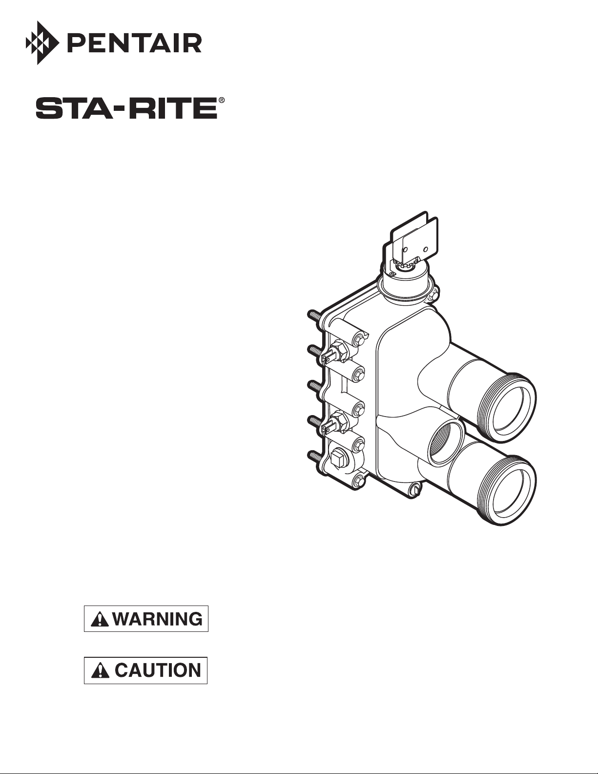
MAX-E-THERM® HEATER
MANIFOLD REPLACEMENT INSTRUCTIONS
HEATER KITS
• 200K Manifold Kit No. 77707-0014
• 333K Manifold Kit No. 77707-0015
• 400K Manifold Kit No. 77707-0016
• Connector Tube Kit No. 77707-0017
• O-Ring No. U9-226
SAFTY PRECAUTIONS
Fire or explosion hazard. Disconnect all power to the
heater and close the External Manual Gas Valve before
starting this procedure.
Compressed spring hazard. The Thermal Regulator plug
has a spring behind it. Restrain it when removing it from the
Manifold to prevent it from flying and possibly injuring
persons nearby (see Picture No. 9, Page 3).
2
Inlet from
Filter
3873 0101
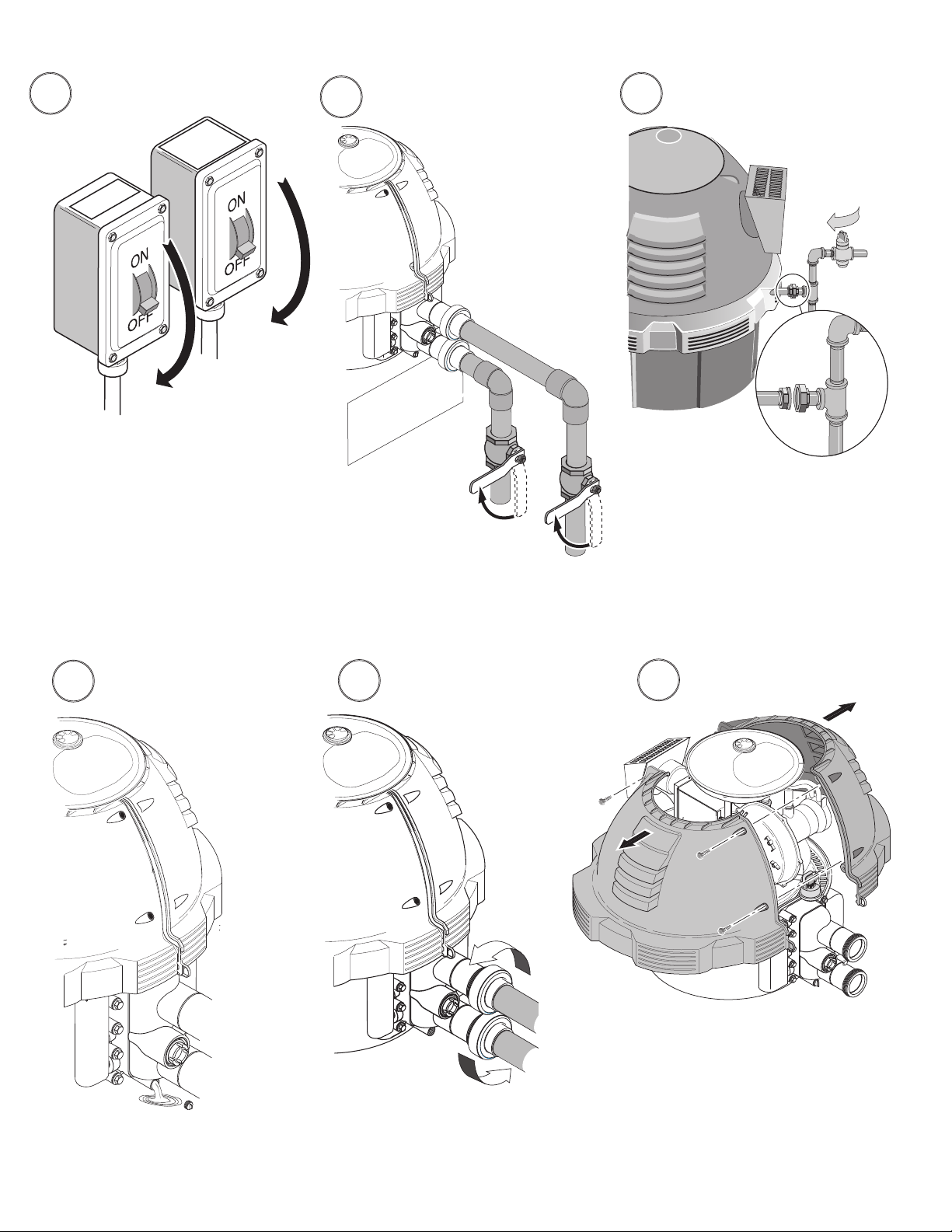
1
Filter
Pump
Heater
3871 0101
Turn off the power to the
heater and the filter pump.
2 3
Outlet to
Pool
Close the gas valve. If it is
necessary to move the heater,
disconnect the union.
3872 0101
Close water inlet and outlet valves to
isolate the heater from the system.
4 5 6
Loosen the union collars.
Drain the Heater.
Max-E-Therm Heater Manifold Replacement Instructions
When the heater is empty,
disconnect the unions.
Separate and remove the covers.
Max-E-Therm Heater Manifold Replacement Instructions
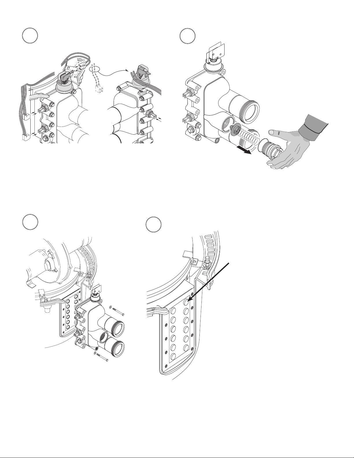
7 8
Remove the switch covers and disconnect the
wires from the safety switches. The wires are
color coded and marked for the switches they
are connected to.
3
Carefully remove the spring-loaded
thermal regulator.
9
Carefully remove the MANIFOLD
and ADAPTER.
10
1. Clean the tube sheet and
O-ring sealing surface with
a nylon brush, then brighten
the tube sheet surface with
320 grit emery cloth. NOTE:
When cleaning, be careful
not to push the tube sheet
into the combustion chamber.
If you do, thread a couple of
bolts into it and pull it back in
place.
2. Brush off all dust and debris
with a brush and wipe it
down with a cloth.
3. Apply silicone grease
(supplied) to O-Rings.

4
12
3
710
54
98
Torque Pattern - All Models
11
• Install O-rings on tube ends; install
manifold.
12
6
75-115 in.-lbs./8.4-12.9 N-m
• Install bolts and hand tighten.
1. Be sure that all bolts are engaged and
hand tight.
13
2. Torque the bolts in sequence as shown.
Some noise (pop- ping, etc.) is normal as
you tighten.
3. Go around the manifold and retighten
the bolts as needed to 75-115 in.-lbs.
(8.4-12.9 N-m) (you may have to do this
several times).
Install the Thermal Regulator in the Manifold.
Max-E-Therm Heater Manifold Replacement Instructions
Max-E-Therm Heater Manifold Replacement Instructions

14
5
Reconnect wires to switches.
NOTE: You may have to reroute the AGS
wire to the opposite side of the manifold
(depending on your heater’s production
date). If so, be sure that the wire crosses
ahead of the Water Pressure Switch as
shown and does not touch the Combustion Chamber.
15
3/8"
NOTICE
Drill Hole
1/4" Dia.,
Centered
Install the second switch cover as
shown when retrofitting a new manifold.
Cut away to
clear Switch Cover
• Start and run the filter pump for several minutes before starting the heater in order to purge all
air from the system. Open all air vents in the system (on Filter, Strainer, etc.) while purging the
air. Run the pump with the vents open until all vents run a solid stream of water.
• Check gas union(s) for leaks with soapy water before firing the heater.
• Explosion and fire hazard. Be sure that all gas connections are tight and
do not leak before attempting to start the heater.
• See Step 15, above, for switch cover installation instructions.
• Have a No. 77707-0008 Insulation Kit on hand in case the heating coil shifts during manifold
installation and requires opening the combustion chamber cover to realign it.
6
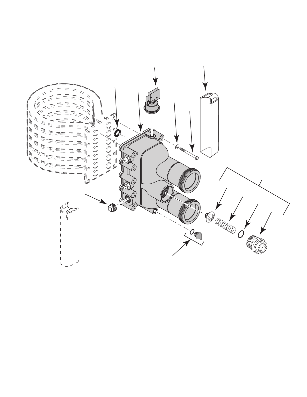
12
Illustrated Parts
13
1
2
3
6
4
5
7
8
9
10
11
Max-E-Therm Heater Manifold Replacement Instructions
Max-E-Therm Heater Manifold Replacement Instructions

Parts List
Key Part Description Qty. 200 Manifold 333 Manifold 400 Manifold
Conversion Kit Conversion Kit Conversion Kit
77707-0014 77707-0015 77707-0016
1 Coil/Tube Sheet Seal O-ring () 35505-7222 (6)* 35505-7222 (10)* 35505-7222 (12)*
• Manifold O-Ring 1 35505-7437 35505-7437 35505-7437
3 Water Pressure Switch 1 42001-0060* 42001-0060* 42001-0060*
2 Manifold/Connector Tube Assy 1 * * *
4 Flat Washer 10 U43-41SS U43-41SS U43-41SS
5 5/16x2-3/4” SS Hx Hd Capscrew () 37007-0214(8)* 37007-0214(10)* 37007-0214(8)*
6 Switch Cover 1 42001-0007* 42001-0007* 42001-0007*
• Switch Cover Screw 1 U30-742SS U30-742SS U30-742SS
7 Thermal Regulator Assembly
(Purchase Separately;
Includes Key Nos. 8,9,10,11) 1 77707-0010 77707-0010 77707-0010
8 Thermal Regulator 1
9 Thermal Regulator Spring 1
10 Thermal Regulator Cap O-Ring 1
11 Thermal Regulator Cap 1
12 Drain Plug 1 U178-920P U178-920P U178-920P
13 3/4" Plug 1 U78-60ZPS* U78-60ZPS* U78-60ZPS*
• Relief Valve ** 473715Z 473715Z 473715Z
• Connector Tube Kit
(Includes O-Ring) 2 77707-0017 77707-0017 77707-0017
• Connector Tube O-Ring 2 U9-226 U9-226 U9-226
• Not illustrated.
* Not available separately. If the manifold body fails, purchase a complete Manifold Conversion Kit,
which includes all safety switches and all internal components except the Thermal Regulator (Key
No. 7, above). Does not include relief valve.
** Purchase separately; required on Canadian installations.

1620 HA
WKINS AVE., SANFORD, NC 27330 • (919) 566-8000
10951 WEST LOS ANGELES AVE., MOORPARK, CA 93021 • (805) 553-5000
www.pentair.com
All Pentair trademarks and logos are owned by Pentair or one of its global aliates. Star-Rite®, Max-E-Therm® are trademarks and/or
registered trademarks of Pentair Water Pool and Spa, Inc. and/or its aliated companies in the United States and/or other countries.
Because we are continuously improving our products and services, Pentair reserves the right to change specications without prior notice.
Pentair is an equal opportunity employer.
© 2019 Pentair Water Pool and Spa, Inc. All rights reserved. This document is subject to change without notice.
*S570*
P/N S570.B 10/2019
 Loading...