

Pentair MASTERTEMP MT200HD, MASTERTEMP MT300HD, MASTERTEMP MT400HD Installation And User Manual
1 1
MASTERTEMP™ POOL AND SPA EURO HEATER
INSTALLATION AND USER’S GUIDE
FOR YOUR SAFETY - READ BEFORE OPERATING
If you do not follow these instructions exactly , a fire or explosion may result, causing
property damage, personal injury or loss of life. For additional free copies of this
manual; call USA (800) 831-7133
FOR YOUR SAFETY - This product must be installed and serviced by authorized personnel, qualified in pool/spa
heater installation. Improper installation and/or operation can create carbon monoxide gas and flue gases which can
cause serious injury, property damage, or death. For indoor installations, as an additional measure of safety, Pentair
Aquatic Systems strongly recommends installation of suitable Carbon Monoxide Detectors in the vicinity of this
appliance and in any adjacent occupied spaces. Improper installation and/or operation will void the warranty.
Models
(240 VAC)
MT200HD, EURO
MT300HD, EURO
MT400HD, EURO
alteration, service or maintenance can
cause property damage, personal injury or death.
Natural Gas
(G20, G25)
461082 461083
461086 461087
461090 461091
Propane Gas
(G31)
COUNTRY OF DESTINATION:
GB, BE, FR, DE
Improper installation, adjustment,
0087
1312
OWNER:
Retain For
Reference
Installation and service must be performed by a qualified
installer , service agency or the gas supplier.
NOx CLASS 5
FOR YOUR SAFETY
• If you do not follow these instructions exactly, a fire or explosion may result, causing property damage,
personal injury or loss of life.
• Improper installation, adjustment, alteration, service or maintenance can cause property damage, personal
injury or death. Installation and service must be performed by a qualified installer , service agency or the gas
supplier.
• Do not place articles or against this appliance.
• Do not use or store flammable materials near this appliance.
• Do not spray aerosols in the vicinity of this appliance while it is in operation.
Future
WHAT TO DO IF YOU SMELL GAS
• Do not try to light any appliance.
FOR
YOUR
• Do not touch any electrical switch; do not use any phone in your building.
• Immediately call your gas supplier from a neighbor's phone.
Follow the gas supplier's instructions.
• If you cannot reach your gas supplier, call the fire dep artment.
SAFETY
DO NOT store or use gasoline or other flammable vapors and liquids in the vicinity
of this or other appliances.
Pentair Water Pool and Spa, Inc. EMEA – Head Office: Industriepark, Wolfstee, Toekomstlaan 30, 2200 Herentals - Belgium.
Pentair Water Pool and Spa, Inc. USA – 1620 Hawkins Ave., Sanf ord, NC 27330, USA • (919) 566-8000 • (800) 831-7133 –
www. pentaireurope.com - www.pentairwater.com.au - www.pentairpool.com - www.staritepool.com
P/N 475106 Rev. D 1/2016 MASTERTEMP™ Pool and Spa Heater Installation and User’s Guide
10951 W. Los Angeles Ave., Moorpark, CA 93021, USA • (805) 553-5000 • (800) 831-7133
| Technical Data
i
Technical Data
General Specifications
GAS TYPE:
GAS GROUP:
GAS SUPPLY PRESSURE:
TYPE OF APPLIANCE:
COUNTRY OF DESTINATION:
READ THE TECHNICAL INSTRUCTIONS BEFORE INST ALLING THIS APPLIANCE.
READ THE INSTALLATION AND USER’S GUIDE BEFORE LIGHTING THIS APPLIANCE.
WARNING!
1312
0087
6
MASTERTEMP™ POOL HEATER
0087
1312
DESIGN AND MANFACTURED BY PENTAIR WATER POOL AND SPA, INC.
MODEL NO.
SERIAL NO.
GAS SUPPLY PRESSURE:
G20:
G31:
TEST POINT PRESSURE
MAX. WORKING PRESSURE
APPLIANCE CATEGORY
COUNTRY OF DESTINATION
YEAR OF MANUFACTURE
ELECTRICAL RATINGS:
VOLTS:
HERTZ:
AMPS:
APPROVED FOR INDOOR AND OUTDOOR INSTALLATIONS ELECTRICAL COMPLIANCE: IN ACCORDANCE
WITH LOCAL ELECTRICAL CODES.
THIS APPLIANCE MUST BE INSTALLED IN ACCORDANCE WITH THE EUROPEAN STANDARD INSTALLATION
CODES, AND WITH THE REQUIREMENTS OF THE AUTHORITY HAVING JURISDICTION.
mbar,
mbar
G25:
mbar
3.45 mbar
GB, BE, DE, FR
mbar
Hz
12 A
THIS HEATER IS EQUIPPED TO BURN
INPUT RATE
ORIFICE SIZE
OUTPUT
ALTITUDE
MINIMUM CLEARANCE FROM COMBUSTIBLE
CONSTRUCTED 15 CM REAR, 15 CM TOP
DO NOT INSTALL THIS HEATER UNDER AN OVERHANG
LESS THAN 1 METER FROM THE TOP. THE AREA UNDER
THE OVERHANG MUST BE OPEN ON THREE (3) SIDES.
V
REFER TO THE OPERATING INSTRUCTIONS FOR
APPROVED WATER TREATMENT.
TYPE G23
GAS
kW
mm
kW
2000 m
Label P/N
P/N 475106 Rev . D 1/2016
MASTERTEMP™ Pool and Spa Heater Installation and User’s Guide P/N 475106 Rev. D 1/2016

Contents |
Contents
T echnical Data / Heater Identification Information (HIN) .................................................................................................................................... ii - iii
Code Requirements / References .................................................................................................................................................................... iv
Consumer Information and Safety / Warnings and Safety Instructions / General Specifications............................................................ v - vii
Section 1. Operations ........................................................................................................................... 1
Overview / Important Notices / Warranty Information .................................................................................................................. 1
Using the Heater’s Control Panel.................................................................................................................................................... 2
Operating Instructions / Basic System Operation ........................................................................................................................ 3
Basic System Operation / HSI (Hot-Surface Ignition) Lighting/Operation.................................................................................. 3
Start-up and Operation .................................................................................................................................................................... 3
Operating Instructions ..................................................................................................................................................................... 4
To Turn Off Gas to Appliance .......................................................................................................................................................... 4
Safety Controls: Air Flow Switch (AFS) / Water Pressure Switch / Height Limit Devices .......................................................... 5
Operation of Ignition Module ........................................................................................................................................................... 6
T emperature Setting / Maximum Temperature Set Point ............................................................................................................... 6
Section 2. Installation Instructions ...................................................................................................... 7
Heater Description................................................................................................................................................................................ 7
Sequence of Operation......................................................................................................................................................................... 7
Putting the Heater into Service ............................................................................................................................................................ 8
Specifications ...................................................................................................................................................................................... 8
Plumbing Connections.......................................................................................................................................................................... 9
Valves .................................................................................................................................................................................................. 9
Manual By-Pass .................................................................................................................................................................................. 9
Water Connections ............................................................................................................................................................................... 10
Below Pool Installation ......................................................................................................................................................................... 10
Gas Connections ................................................................................................................................................................................. 11
Gas Pipe Sizing ................................................................................................................................................................................... 11
Sediment Trap/Drip Leg ....................................................................................................................................................................... 11
T esting Gas Leaks and Gas Pressure.................................................................................................................................................. 12
Gas Pressure Requirements ................................................................................................................................................................ 12
Outdoor Installation / Heater Clearances .............................................................................................................................................. 13 - 14
Indoor Venting—General Requirements / Heater Clearances / Outside Vent Removal ) .................................................................... 15- 16
Combustion Air Supply .................................................................................................................................................................... 15
Vent Installation (Indoor Installation or Outdoor Shelter) - Vertical Venting...................................................................................... 16
Direct Air Intake Duct with 63 mm (2.5 in) PVC Pipe (Heater Indoor Installation)............................................................................. 16
Horizontal or Vertical Venting - Using Single-Wall Stainless Gas Vent ........................................................................................... 17
Connecting Single-Wall Stainless Steel Vent to the Heater ............................................................................................................. 18 - 19
Corrosive Vapors and Possible Causes.............................................................................................................................................. 20
Control Panel Indexing ....................................................................................................................................................................... 20
Final Installation Check....................................................................................................................................................................... 20
Electrical Connections ........................................................................................................................................................................ 21
Fireman’s Switch Connection/Remote Control Connections .............................................................................................................. 21 - 22
MasterTemp Wiring Diagram / Electrical Schematic Ladder Diagram................................................................................................. 23 - 24
Section 3. Troubleshooting ................................................................................................................. 25
Initial Troubleshooting and Troubleshooting Chart ............................................................................................................................. 25
Heater Will Not Fire Troubleshooting (A, B, C, D) ............................................................................................................................... 26 - 29
LED Diagnostics (AGS, AFS, HLS, PS Thermistor)............................................................................................................................. 30 - 31
Burner / Heat Exchanger Troubleshooting.......................................................................................................................................... 32
Section 4. Maintenance Instructions.................................................................................................. 33
Care and Maintenance ....................................................................................................................................................................... 33
Pressure Relief Valve .......................................................................................................................................................................... 33
After Start-Up....................................................................................................................................................................................... 34
Spring, Fall (Autumn) and Winter Operation ...................................................................................................................................... 34
Maintaining Pool Temperature / Energy Saving Tips .......................................................................................................................... 35
Chemical Balance ............................................................................................................................................................................... 35 - 36
Replacement Parts.............................................................................................................................................................................. 37 - 41
ii
P/N 475106 Rev. D 1/2016 MASTERTEMP™ Pool and Spa Heater Installation and User’s Guide
| Heater Identification Information
iii
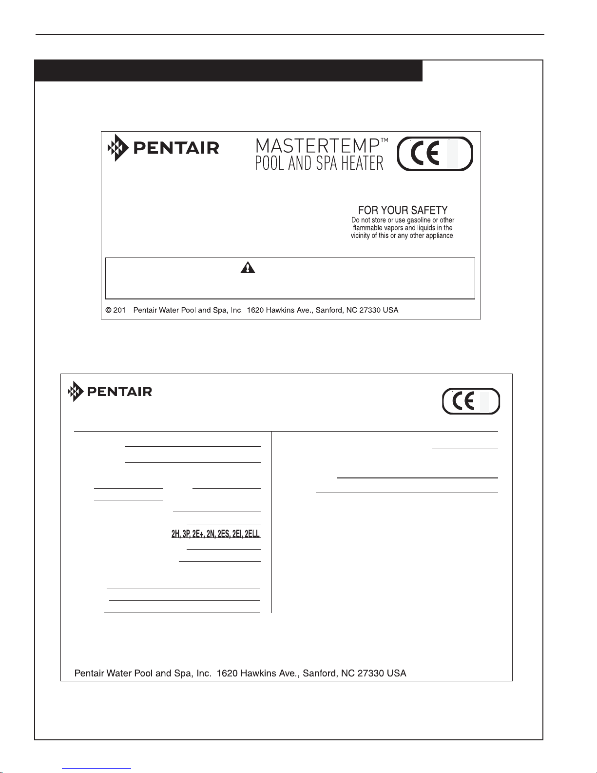
Heater Identification Information (HIN)
To identify the heater, see the data rating plate on the inner front panel of the heater. There are two designators for
each heater, one is the
Model Number and the other is the Heater Identification Number (HIN).
Heater Identification Number (HIN)
The following example simplifies the identification system:
1) MT : MasterTemp
2) Model Size : (200, 300 or 400) : Input rating (Gross BTU/hr)
3) Construction : (HD = Heavy Duty Model)
4) Fuel Type : (LP = Propane gas or NA = Natural gas)
ID DESIGNATOR FOR PENTAIR POOL AND SPA MASTERTEMP™ HEATERS
HEATER IDENTIFICATION NUMBER
Example:
123 4
MT 300 HD
N
H. I. N.
FUEL TYPE =
HD = HEAVY DUTY MODEL
MODEL SIZE = BTU/hr GROSS INPUT
200 (200 [
MT = MASTERTEMP
NA = NATURAL GAS
LP = PROPANE GAS
BTU/hr
), 300 (300 [
BTU/hr
) or 400 (400 [
BTU/hr
)
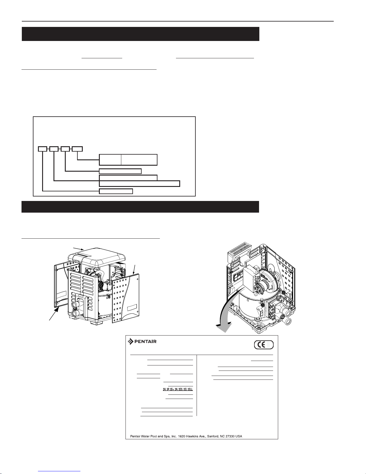
Heater Data Rating Plate
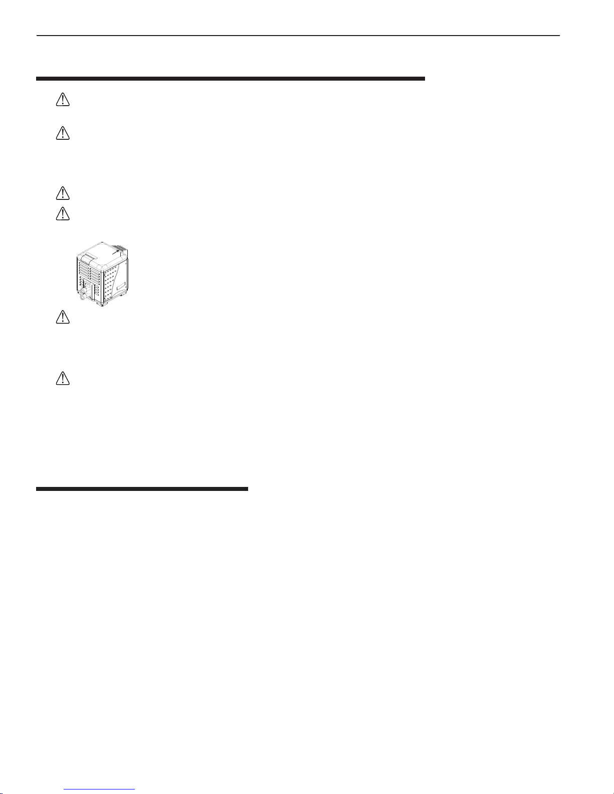
The heater data rating plate is located on the inner front panel of the heater. To access the data rating plate, unbolt and
remove the side door access panel as shown below.
Heater Data Rating Plate Location
Top Panel
Remove this Door
Access Panel to access
the DATA RATING PLATE
Door
Access
Panel
MASTERTEMP™ POOL HEATER
DESIGN AND MANFACTURED BY PENTAIR WATER POOL AND SPA, INC.
MODEL NO.
SERIAL NO.
GAS SUPPLY PRESSURE:
G20:
G31:
TEST POINT PRESSURE
MAX. WORKING PRESSURE
APPLIANCE CATEGORY
COUNTRY OF DESTINATION
YEAR OF MANUFACTURE
ELECTRICAL RATINGS:
VOLTS:
HERTZ:
AMPS:
APPROVED FOR INDOOR AND OUTDOOR INSTALLATIONS ELECTRICAL COMPLIANCE: IN ACCORDANCE
WITH LOCAL ELECTRICAL CODES.
THIS APPLIANCE MUST BE INSTALLED IN ACCORDANCE WITH THE EUROPEAN STANDARD INSTALLATION
CODES, AND WITH THE REQUIREMENTS OF THE AUTHORITY HAVING JURISDICTION.
mbar,
mbar
G25:
3.45 mbar
GB, BE, DE, FR
mbar
THIS HEATER IS EQUIPPED TO BURN
INPUT RATE
ORIFICE SIZE
mbar
OUTPUT
ALTITUDE
MINIMUM CLEARANCE FROM COMBUSTIBLE
CONSTRUCTED 15 CM REAR, 15 CM TOP
DO NOT INSTALL THIS HEATER UNDER AN OVERHANG
LESS THAN 1 METER FROM THE TOP. THE AREA UNDER
THE OVERHANG MUST BE OPEN ON THREE (3) SIDES.
V
REFER TO THE OPERATING INSTRUCTIONS FOR
Hz
12 A
APPROVED WATER TREATMENT.
TYPE G23
kW
kW
2000 m
Label P/N
GAS
mm
0087
1312
MASTERTEMP™ Pool and Spa Heater Installation and User’s Guide P/N 475106 Rev. D 1/2016
Code Requirements / References |
CODE REQUIREMENTS / REFERENCES
Gas Safety (Installation and Use) Regulations, (as amended).
It is the law that all gas appliances are installed by a competent person (e.g. a CORGI registered operative) in accordance with Regulations.
Failure to install appliances correctly could lead to prosecution. The installation of the Heater MUST also be in accordance with the
current I.E.E.. Wiring Regulations, the European Building Standards, the Bye Laws of the Local Water Undertaking, any relevant
requirements of the Local Authority, and Health and Safety document No 635, “Electricity at Work Regulations”.
Detailed recommendations are contained in the following European Standard Codes of Practice.
iV
Installation must be in accordance with the code requirements:
• Manufacturer’s Installation Instructions
• Local Gas Fitting Regulations
• Municipal Building Codes
•
EN 437: 2003 + A1 (2009) Test Gases - Test
pressures appliances categorizes.
•
EN 60335-2-102/A1 - Household and similar
electric appliances - Safety - 2- 2012
• BS 6891 Specification for installation of
low pressure gas pipe work.
• BS5482:1 Code of practice for domestic
butane and propane gas burning
installations. Building Regulations|
Part L1.
IMPORTANT NOTICE:
DO NOT directly connect any external control device to this appliance, unless noted in this Installation and User’s Guide
or recommended by the manufacturer. Any installed control device not recommended by the manufacturer could violate
the Gas Safety Regulations (the installation and use), the above described regulations and the appliance warranty.
The manufacturer’s notices DO NOT supersede any legal requirements.
• Local Electrical Regulations
• Any other statutory regulations
•E
N 15502-1 : 2012 Gas fired heating
boilers general requirements test.
• BS 6644 : 2011 Specifications for
the installation and maintenance of
gas fired hot water boilers between
70Kw - 1.8 mW, (2nd. and 3rd. gas
family).
1312
0087
P/N 475106 Rev. D 1/2016 MASTERTEMP™ Pool and Spa Heater Installation and User’s Guide

| Code Requirements / References
V
CONSUMER INFORMA TION AND SAFETY
THE MASTERTEMP HEATER IS CLASSIFIED AS A CLASS 5 LOW NOX BOILER.
WARNING
Should overheating occur or the gas supply fail to shut off, turn off the manual gas control valve to the heater. Do not
use this heater if any part has been under water. Immediately call a qualified service technician to inspect the heater
and to replace any part of control system and gas control which has been under water.
D ANGER
CARBON MONOXIDE GAS IS DEADLY – Exhaust from this pool heater contains toxic levels of carbon monoxide, a dangerous,
poisonous gas you cannot see or smell.
WARNING
The Consumer Product Safety Commission warns that carbon monoxide is an "invisible killer". Carbon monoxide is a
colorless and odorless gas.
1. Carbon monoxide is produced by burning fuel, including natural gas and propane.
2. Proper installation, operation and maintenance of fuel-burning appliances in the home is the most important factor in reducing
carbon monoxide poisoning.
3. Be sure that fuel burning appliances such as heaters are installed by professionals according to manufacturer's instructions and
codes.
4. Always follow the manufacturer's directions for safe operation.
5. Have the heating system (including vents) inspected and serviced annually by a trained service technician.
6. Examine vents regularly for improper connections, visible cracks, rust or stains.
7. Install battery-operated carbon monoxide alarms. The alarms should be certified to the requirements of the most recent UL, CE,
IAS, CSA and IAPMO standard for carbon monoxide alarms. T est carbon monoxide alarms regularly and replace dead batteries.
WARNING
The Consumer Product Safety Commission warns that elevated water temperature can be hazardous. See below
for water temperature guidelines before setting temperature.
1. Spa or hot tub water temperatures should never exceed 40° C. A temperature of 37° C. is considered safe for a healthy adult.
Special caution is suggested for young children. Prolonged immersion in hot water can induce hyperthermia.
2. Drinking of alcoholic beverages before or during spa or hot tub use can cause drowsiness which could lead to unconsciousness
and subsequently result in drowning.
3. Pregnant women beware! Soaking in water above 37° C. can cause fetal damage during the first three months of pregnancy
(resulting in the birth of a brain-damaged or deformed child). Pregnant women should stick to the 37° C. maximum rule.
4. Before entering the spa or hot tub, the user should check the water temperature with an accurate thermometer . Spa or hot tub
thermostats may error in regulating water temperatures by as much as -15° C.
5. Persons with a medical history of heart disease, circulatory problems, diabetes or blood pressure problems should
obtain their physician's advice before using spas or hot tubs.
6. Persons taking medication which induce drowsiness, such as tranquilizers, antihistamines or anticoagulants should
not use spas or hot tubs.
MASTERTEMP™ Pool and Spa Heater Installation and User’s Guide P/N 475106 Rev. D 1/2016

Warnings and Safety Instructions |
vi
W ARNINGS AND SAFETY INSTRUCTIONS
The MasterTemp pool heaters are designed and manufactured to provide many years of safe and reliable service when
installed, operated and maintained according to the information in this manual. Throughout the manual, safety warnings and
cautions are identified by the “ “ symbol. Be sure to read and comply with all of the warnings and cautions.
DANGER — CARBON MONOXIDE GAS IS DEADLY
• • READ OWNERS MANUAL COMPLETELY BEFORE OPERATING. • •
THIS PRODUCT MUST BE INSTALLED AND SERVICED BY A PROFESSIONAL SERVICE
TECHNICIAN, QUALIFIED IN POOL HEATER INSTALLATION. Some jurisdictions require that
installers be licensed. Check with your local building authority about contractor licensing requirements.
Improper installation and/or operation could create carbon monoxide gas and flue gases which could
cause serious injury or death. Improper installation and/or operation will void the warranty.
Exhaust from this pool heater contains carbon monoxide, a dangerous, poisonous gas you cannot
see or smell. Symptoms of carbon monoxide exposure or poisoning include dizziness, headache,
nausea, weakness, sleepiness, muscular twitching, vomiting and inability to think clearly. IF YOU
EXPERIENCE ANY OF THE ABOVE SYMPTOMS, IMMEDIATELY TURN OFF THE POOL
HEATER, LEAVE THE VICINITY OF THE POOL OR SPA AND GET INTO FRESH AIR IMMEDIATELY.
THE POOL HEATER MUST BE THOROUGHLY TESTED BY A GAS PROFESSIONAL BEFORE
RESUMING OPERATION.
EXCESSIVE CARBON MONOXIDE EXPOSURE CAN CAUSE BRAIN DAMAGE OR DEATH.
Install this pool heater far from open windows, doors, vents and other openings, see page 16 for
minimum distances.
Pentair strongly recommends that all vents, pipes and exhaust systems be initially and periodically
tested for proper operation. This testing can be accomplished by using a hand-held carbon monoxide
meter and/or by consulting with a gas professional.
Pool heaters must be used in conjunction with carbon monoxide detectors installed near the pool
heater. The carbon monoxide detectors must be periodically inspected for proper operation so as to
insure continued safety. Broken or malfunctioning carbon monoxide detectors must be replaced
immediately.
WARNING —
WARNING —
P/N 475106 Rev. D 1/2016 MASTERTEMP™ Pool and Spa Heater Installation and User’s Guide
This heater is equipped with an unconventional gas control valve that is factory set with a
manifold pressure of 1.1 ± 0.5 mbar. Improper installation, adjustment, alteration, service or
maintenance can cause property damage, personal injury or loss of life. Installation or service must
be performed by a qualified installer, service agency or the gas supplier. If this control is replaced, it
must be replaced with an identical control.
Do not attempt to adjust the gas flow by adjusting the regulator setting.
Risk of fire or explosion from incorrect fuel use or faulty fuel conversion. Do not try to run a
heater set up for G20, G25 or G31 gas or vice versa. Only qualified service technicians should attempt to
convert heater from one fuel to the other. Do not attempt to alter the rated input or type of gas by
changing the orifice. If it is necessary to convert to a different type of gas, consult your Pentair dealer .
Serious malfunction of the burner can occur which may result in loss of life. Any additions, changes,
or conversions required in order for the appliance to satisfactorily meet the application needs must
be made by a Pentair dealer or other qualified agency using factory specified and approved parts.
The heater is available for use with G20, G25 or G31 gas only . It is not designed to operate with any other
fuels. Refer to the nameplate for the type of gas the heater is equipped to use.
• Use heater only with the fuel for which it is designed.
• If a fuel conversion is necessary , refer this work to a qualified service technician or gas supplier
before putting the heater into operation.
| Warnings and Safety Instructions
vii
W ARNINGS AND SAFETY INSTRUCTIONS (continued)
WARNING —
WARNING —
WARNING —
WARNING —
Vent
Cover
Risk of fire or explosion from flammable vapors. Do not store gasoline, cleaning fluids, varnishes,
paints, or other volatile flammable liquids near heater.
Risk of explosion if unit is installed near G31 gas storage. G31 gas is heavier than air. Consult
local codes and fire protection authorities about specific installation requirements and restrictions.
Locate the heater away from propane gas storage and filling equipment as specified by the Standard
for the Storage and Handling of G31 (latest edition).
Risk of fire. Do not place articles on, near or against the heater.
Risk of burn hazard. To reduce the risk of injury, do not touch the side heater vent cover when
the heater is operating. Side heater vent covers are HOT and can burn when touched causing
personal injury. Do not allow children to play on or around heater or associated equipment.
THE AVERAGE TEMPERATURE OF THE HEATERS FLUE EXHAUST IS 204 DEGREES
CELSIUS (°C).
WARNING —
CAUTION —
Risk of asphyxiation if exhaust is not correctly vented. Follow venting instructions exactly
when installing heater. Do not use a draft hood with this heater, as the exhaust is under
pressure from the burner blower and a draft hood will allow exhaust fumes to blow into the room
housing the heater. The heater is supplied with an integral venting system for outdoor installation.
Label all wires prior to disconnection when servicing controls. Wiring errors can cause
improper and dangerous operation. Wiring errors can also destroy the control board.
• Connect heater to 240 Volt, 50 Hz., Single Phase power only.
• Verify proper operation after servicing.
• Do not allow children to play on or around heater or associated equipment.
• Never allow children to use the pool or spa without adult supervision.
• Read and follow other safety information contained in this manual prior to operating this pool heater.
GENERAL SPECIFICA TIONS
NOTICE:
• Combustion air contaminated by corrosive chemical fumes can damage the heater and will void the warranty.
• The Combination Gas Control Valve on this heater differs from most appliance gas controls. If it must be replaced,
for safety reasons replace it only with an identical gas control.
• The access door panels must be in place to provide proper ventilation. Do not operate the heater for more than five (5)
minutes with the access door panels removed.
• This heater is design certified by CERTIGAZ as complying with the Standard for Gas Fired Pool Heaters, and is intended
for use in heating fresh water swimming pools or spas.
• The heater is designed for the heating of chlorine, bromine or salt system swimming pools and spas. It should NOT be
used as a space heating boiler, or general purpose water heater. The heater requires an external 240 VAC
single-phase electric power source.
• The heater should be located in an area where leakage of the heater or connections will not result in damage to the
area adjacent to the heater or to the structure. When such locations cannot be avoided, it is recommended that a
suitable drain pan, adequately drained, be installed under the heater. The pan must not restrict air flow.
• The heater may not be installed within 3.5 m (11.5 ft.) of the inside surface of a pool or spa unless it is separated by a
solid fence, wall or other permanent barrier.
MASTERTEMP™ Pool and Spa Heater Installation and User’s Guide P/N 475106 Rev. D 1/2016
Section 1. Overview
| 1
Introduction
MasterTemp™ P ool and Spa Heater
Congratulations on your purchase of a MasterT emp™ high performance heating system. Proper installation and service of
your new heating system and correct chemical maintenance of the water will ensure years of enjoyment. The MasterT emp
is a compact, lightweight, efficient, induced-draft, gas fired high performance pool and spa heater that can be directly
connected to 63 mm (2 in) PVC pipe. The MasterT emp also comes equipped with a multifunction temperature controller
which shows, at a glance, the proper functioning of the heater. All MasterT emp heaters are designed with a direct ignition
device, HSI (hot-surface ignition), which eliminates the need for a standing pilot. The MasterTemp requires an external
power source (240 VAC 50 Hz) to operate.
SPECIAL INSTRUCTIONS TO OWNER: Retain this manual for future reference. This instruction manual provides
operating instructions, installation and service information for the MasterT emp high performance heater. The information in
this manual applies to all MasterTemp models. READ AND REVIEW THIS MANUAL COMPLETELY, it is very
important that the owner/installer read and understand the section covering installation instructions, and recognize the European
Standard Codes of Practice before installing the MasterT emp. Its use will reduce service calls and chance of injury and will
lengthen product life. History and experience has shown that most heater damage is caused by improper installation practices.
IMPORT ANT NO TICES
THIS PRODUCT MUST BE INSTALLED AND SERVICED BY A PROFESSIONAL SERVICE TECHNICIAN, QUALIFIED
IN POOL HEATER INSTALLATION.
For the installer and operator of the MasterTemp pool and spa heater: The manufacturer’s warranty may be
void if, for any reason, the heater is improperly installed and/or operated. Be sure to follow the instructions set forth in
this manual. If you need more information or if you have any questions regarding to this pool heater, please contact
Pentair Water Pool and Spa, Inc. EMEA – Head Office: Industriepark, Wolfstee, Toekomstlaan 30, 2200 Herentals
- Belgium or Pentair Water Pool and Spa, USA – at (800) 831-7133 • (919) 566-8000 • (805) 553-5000.
W ARRANTY INFORMA TION
The MasterTemp pool heater is sold with a limited factory warranty. Specific details are described on the warranty
registration card which is included with the product. Return the warranty registration card after filling in the serial
number from the rating plate inside the heater.
High standards of excellence include a policy of continuous product improvement results in your state-of-the-art
heater. We reserve the right to make improvements which change the specifications of the heater without incurring
an obligation to update the current heater equipment.
These heaters are designed for the heating of chlorine, bromine or salt system swimming pools and spas or
in non-stationary installations, and should never be employed for use as space heating boilers or general
purpose water heaters. The manufacturer’s warranty may be void if, for any reason, the heater is improperly
installed and/or operated. Be sure to follow the instructions set forth in this manual.
OPERATING THIS HEATER CONTINUOUSLY AT WATER TEMPERATURE BELOW 20°C. WILL CAUSE HARMFUL
CONDENSATION AND WILL DAMAGE THE HEATER AND VOID THE WARRANTY. Do not use the heater to protect
pools or spas from freezing if the final maintenance temperature desired is below 20°C, as this will cause condensation
related problems.
P/N 475106 Rev. D 1/2016 MASTERTEMP™ Pool and Spa Heater Installation and User’s Guide
CAUTION
2 | Section
1. Operations
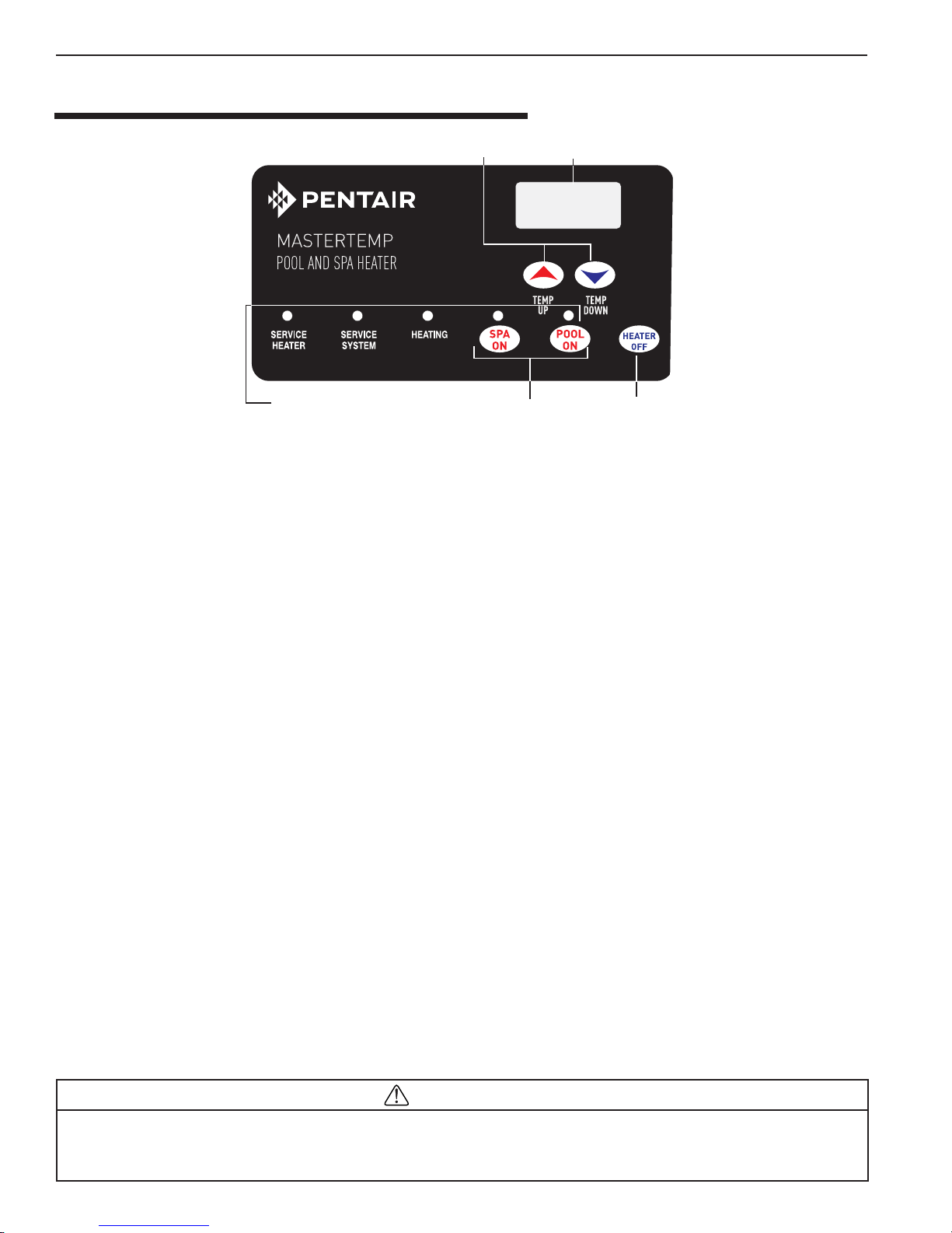
USING THE HEATER’S CONTROL PANEL
Temperature
Up and Down
System Operation
Indicator Lights
Digital Temperature
Display
Dual Temperature
Controls
Heater "OFF"
Switch
The MasterT emp heater controls are as follows:
POOL ON Press this button to control the heater operation by the pool temperature setting.
SP A ON Press this button to control the heater operation by the spa temperature setting.
HEA TER OFF Press this button to switch off the heater .
TEMP Press this button to raise the temperature setting.
TEMP Press this button to lower the temperature setting.
T o toggle the display between degrees Centigrade (°C) and degrees Fahrenheit (°F):
1. Press the HEATER OFF button to switch the heater OFF.
2. Press TEMP or TEMP for five (5) seconds. The display will flash once and change modes (°C to °F or
vice versa).
3. Press the HEATER OFF button to switch the heater ON.
When either the TEMP or TEMP buttons are pressed, the digital display will indicate the temperature setting. After
five seconds, the display will return to the actual pool/spa temperature.
In addition to the digital temperature LED display, there are five indicator LEDs:
The POOL ON light indicates that the pool water temperature is governing operation of the heater.
The SPA ON light indicates that the spa water temperature is governing operation of the heater.
The HEATING light comes on and stays on when the heater’s burner chamber is firing. This light should be on whenever
the burner is on. This light blinks when the heater is calling for heat but not firing. If this light is on but the burner fails to
come on, one of the “service” lights should come on, indicating a fault in the system.
The SER VICE SYSTEM light indicates that there is insufficient water flow to the heater. If the pump is operating, this
usually indicates that the filter and/or skimmers should be cleaned (some filters may require back-washing). If the light
remains on after the filter/skimmers have been serviced, the system should be checked by a qualified service technician.
The SER VICE HEATER light indicates a fault in the heater or its controls. If this light comes on, shut down the heater
(See “TO TURN OFF GAS T O THE APPLIANCE” on page 4), and have a qualified service technician check the system.
Risk of explosion or fire causing burns or death if safety interlocks are disabled. DO NOT attempt to operate heater
when SERVICE HEATER light is on or if blower or burner will not start. Instead, follow instructions under “To Switch Off Gas to
the Appliance,” and call a qualified service technician to repair unit.
MASTERTEMP™ Pool and Spa Heater Installation and User’s Guide P/N 475106 Rev. D 1/2016
WARNING
Section 1. Operations
| 3
Operation Instructions
BASIC SYSTEM OPERATION
Start pump, make sure the pump is running and is primed, to close the water pressure switch and supply
power to heater. Be sure the pool and/or spa is properly filled with water. Follow the Lighting/Operating instructions
below .
MASTERTEMP HSI ELECTRONIC IGNITION LIGHTING/OPERATION
FOR YOUR SAFETY: READ BEFORE LIGHTING
WARNING
If you do not follow these instructions e xactly, a fire or explosion ma y result causing
property damage, personal injury or loss of life.
Do not attempt to light the heater if you suspect a gas leak. Lighting the heater can result
in a fire or explosion which can cause personal injury , death, and property damage.
WARNING! DO NOT INTERFERE WITH ANY SEALED COMPONENTS. THIS CAN ONLY BE
DONE BY A QUALIFIED SERVICE PROFESSIONAL.
THE MASTERTEMP HEATER IS INTENDED FOR INSTALLATION WITH A METERED GAS PRESSURE REGULATOR.
START-UP AND OPERATION
START-UP AND SHUTDOWN INSTRUCTIONS ARE ON THE LABEL ATTACHED TO THE COVER OF THE
APPLIANCE CONTROL BOX.
NOTICE: UPON INSTALLATION THE INSTALLER MUST INSTRUCT THE USER IN THE OPERATION AND SAFETY
DEVICES AND PROVIDE A COPY OF THE HEATER’S USER’S GUIDE.
BEFORE START-UP
A. This appliance does not have a pilot. It is equipped with
an ignition device which automatically lights the burners.
Do not try to light the burners by hand.
B. BEFORE OPERATING, smell all around the
appliance area for gas. Be sure to smell next to the floor
because some gas is heavier than air and will settle on
the floor.
WHAT TO DO IF YOU SMELL GAS
– Do not try to light any appliance.
– Do not touch any electrical switch; do not use any phone
in your building.
– Immediately call your gas supplier from a neighbor's
phone. Follow the gas supplier's instructions.
– If you cannot reach your gas supplier, call the Fire
Department.
C. Use only your hand to turn the gas control on or off.
Never use tools. If you cannot change the ON/OFF
setting by hand, don't try to repair it, call a qualified
service technician. Forced or attempted repair may result
in a fire or explosion.
D. Do not use this heater if any part has been under water .
Immediately call a qualified service technician to inspect
the heater and to replace any part of the control system
and any gas control which has been under water.
E. Do not operate the pool heater unless the pool or spa is
properly filled with water.
F. Before operating the appliance for the first time or after
it has been off for an extended time, perform the
following checklist:
1. Remove debris or other articles from inside the heater
and the area around the heater and its exhaust vent.
Make sure the ventilation openings are clear of debris
or obstruction. For installations in an enclosed space,
make sure openings for combustion and ventilation
air are unobstructed.
2. Keep heater area clear and free from combustibles,
flammable liquids and chemicals.
3. Check that all water connections are tight.
4. Water must be flowing through the heater during
operation. Make sure that pool/spa is filled with water
and have pump operating. Check that water flow is
unobstructed from the appliance. When operating for
the first time or after an extended shut-down, run
filter pump for several minutes to clear all air from
the system.
P/N 475106 Rev. D 1/2016 MASTERTEMP™ Pool and Spa Heater Installation and User’s Guide
4 | Section
1. Operations
OPERA TING INSTRUCTIONS
1. STOP! Read the safety information on (page v - vii).
2. Set both pool and spa thermostats to the lowest
settings.
3. Turn off all electric power to the appliance.
4. This appliance does not have a pilot. It is equipped
with an ignition device which automatically lights
the burner. Do not try to light the burner by hand.
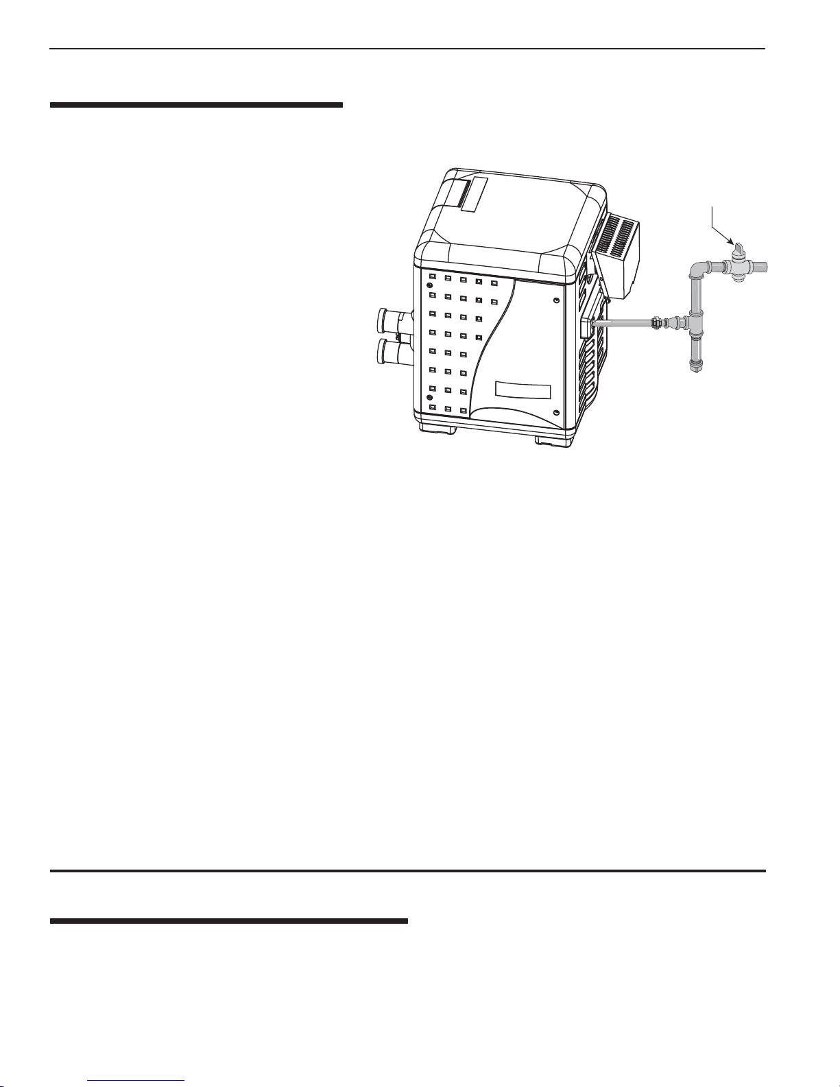
5. Turn off the outside external manual shut-off gas
valve, see Figure 1.
W ait five (5) minutes to clear out any gas. If you
6.
then smell gas, STOP! Follow “B” in the “Before
Start-up” instructions (page 3). If you don’t smell
gas, go to the next step.
Turn on the outside external manual shut-off gas
7.
valve, see Figure 1.
External Manual
Shut-off Valv e
Figure 1.
Set 3-way valves on inlet and outlet to pool or
8.
spa, as appropriate.
9. Turn on all electric power to the appliance.
10. Press either the POOL ON or SPA ON button switch on the operating control.
1 1 . Set the thermostat to desired setting (NOTICE: Set point must be above actual water temperature or burner will not
fire). See page 2 “OPERATING THE CONTROL PANEL”.
12. The blower should come on immediately, and after about 20 seconds, the burner should fire. When operating for the
first time, the burner may not fire on the first try because of air in the gas line. If it does not fire at first, push the OFF
switch, wait five minutes, and again push the POOL or SPA ON switch. The burner should fire after about 20
seconds. You may have to repeat this until all of the air has cleared the gas line.
13. The burner should fire until the pool/spa temperature reaches the desired temperature set on the thermostat. The
blower will continue to run for about 45 seconds after the burner shuts off. If any of the safety interlocks should open
during burner operation, the burner shuts off immediately, but the blower continues to run for about 45 seconds.
Should overheating occur or the gas supply fail to shut off, turn off the manual gas control valve to the appliance.
14. If the appliance will not operate, follow the instructions below “TO TURN OFF GAS TO THE APPLIANCE”, and
call your service technician or gas supplier.
15. If the electrical power is lost while the heater is running, the heater will retain all program settings and the unit will
come back to it’s original mode and settings once the power is restored.
TO TURN OFF GAS TO APPLIANCE
1. Press the OFF button on operating control.
2. Switch off all electric power to the unit.
3. Turn off the outside external manual shut-off gas valve, see Figure 1.
MASTERTEMP™ Pool and Spa Heater Installation and User’s Guide P/N 475106 Rev. D 1/2016
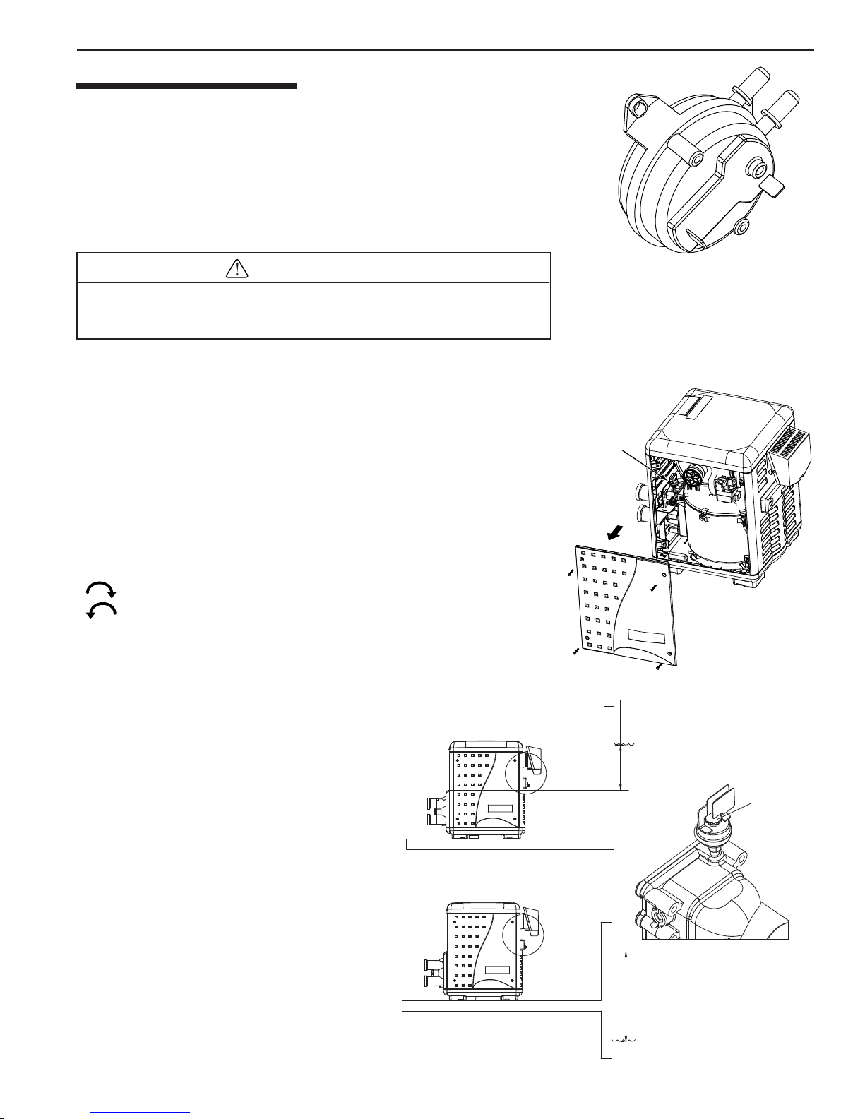
SAFETY CONTROLS
AIR FLO W SWITCH (AFS)
The air flow switch, (see Figure 2), is a safety device used to insure that the
combustion air blower (fan) is operating and has been designed to monitor the
vacuum (negative) pressure within the blower housing. The air flow switch is
factory set and is connected upstream of the ignition module. The ignition module
does not operate unless the air pressure switch and all safety switches are
closed.
Section 1. Operations
| 5
W A TER PRESSURE SWITCH
WARNING
Hazardous pressure. Do not bypass the Water Pressure Switch or render it inoper-
HAZARDOUS PRESSURE. DO NOT BYPASS THE WATER
able.
PRESSURE SWITCH OR RENDER IT INOPERABLE.
WA TER PRESSURE SWITCH
The water pressure switch, (see Figure 3). If the water flow is restricted, the
water pressure switch may prevent the burner from firing and cause the
“Service System” light to go on. If the light remains on after the filter has
been serviced, have a qualified service technician check the system.
For deck-level heater installations, the W ater Pressure Switch is factory set at
0.2 bar (3.00 psi). NOTE: See, Below Pool Level Installation instructions on
page 10. If the pressure switch is .3M (1 ft.) below or above the pool water
level, reset the switch so that it is open when the pump is off and closed
when the pump is running. Turn the star -wheel on the switch clockwise
( ) to raise setting (heater below the pool) and counterclockwise
( ) to lower the setting (heater above the pool – see Figure 4. Test the
switch after resetting.NOTICE: When the heater is mounted more than 1.5M
(5 ft.) above or 1.2M (4 ft.) below the deck level, a Pressure Switch is no
longer adequate. A Flow Switch must be installed instead.
Air Flow Switch
Water
Pressure
Switch
Figure 2.
Figure 4.
NOTICE: Heater operation with incorrect
Pressure Switch setting may cause operation
with no water flow. Operation of the heater
without sufficient water flow may severely
damage it and will void the warranty.
HIGH LIMIT SWITCH
A “High Limit”, is a safety device that opens
the electrical circuit and shuts off the heater
based on a water temperature set point within
the “High Limit Device”. The MasterTemp
series of heaters contains two (2) high limit
devices which are located on the main inlet /
outlet header (see page 41 item 6).
P/N 475106 Rev. D 1/2016 MASTERTEMP™ Pool and Spa Heater Installation and User’s Guide
Turn star wheel clockwise to raise
pressure set point if pressure switch is more
than 1.2 M (4 ft) below water level
A reference scale is on
the back of pressure switch
Turn star wheel counterclockwise to lower
pressure set point if pressure switch is more
than 1.5 M (5 ft) above water level
1.2 M (4 ft)
Star Wheel
1.5 M (5 ft)
Figure 3.
6 | Section
s
1. Operations
SAFETY CONTROLS, (continued)
OPERATION OF IGNITION MODULE
Flame Current
Check Point
Diagnostic LED
1 Flash - Air Flow Fault
2 Flashes - Flame No Call For Heat
3 Flashes - Ignition Lockout
The Ignition Module, (see Figure 5), is microprocessor based and
operates on 24V AC supplied by the transformer . The control utilizes
a microprocessor to continually and safely monitor, analyze, and
control the proper operation of the gas flame holder. The module
with the presence of the flame sensor, using flame rectification,
allows the heater to operate.
Figure 5.
TEMPERA TURE SETTING
The heater comes factory set at 25.6° C (78° F). for the pool mode and 37.8° C (100° F). for the spa mode. Using the up
and down arrows, you can set the pool/spa thermostats to a minimum temperature of 18.3° C (65° F.), or a maximum of
40° C (104° F). If you desire to heat only one body of water, the thermostat is capable of an off mode. As an example, if
you only wish to heat the spa and not the pool, simply depress and hold the pool down arrow, and the thermostat will
lower its setting to 18.3° C (65° F.) then go to an off mode. See below to change the heater ’s factory set temperature
settings.
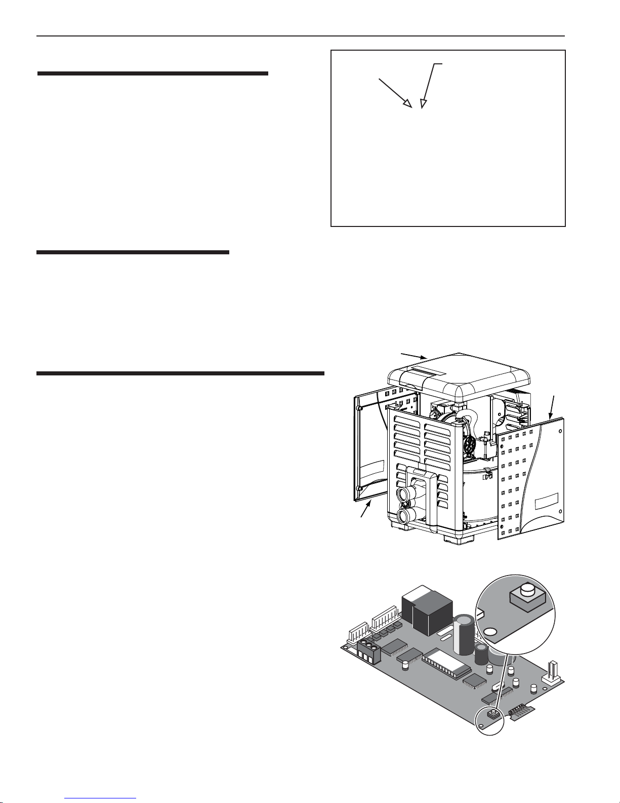
MAXIMUM TEMPERA TURE SET POINT
1. Unbolt and remove the door panels (see Figure 6).
Top Panel
Door
Acces
Panel
2. Access the control panel board on the underside of the top cover.
Locate the yellow button on the corner of the control board.
3. Push the Max. Temp. Set Point button on the back of the
control board (see Figure 7).
The following sequence should happen:
1. The unit turns on and the POOL ON light will
turn on.
2. Press the
TEMP or TEMP button (on TOP of the
control panel) to set maximum pool temperature.
3. W ait up to 30 seconds; the POOL ON light will turn of f
and the SPA ON
light will turn on. T o override the time
delay, push the Max. Temp. Set P oint button again.
4. Press the
TEMP or TEMP button on the control
panel and set maximum spa temperature to 40°C
(104° F) or less.
5. W ait up to 30 seconds; the SPA ON light will turn off
and the unit will shut down. T o override the time delay,
push the Max. Temp. Set P oint
button again.
6. Reinstall the access door panels.
Door
Access Panel
Figure 6.
SET
MA
X
S1
MASTERTEMP™ Pool and Spa Heater Installation and User’s Guide P/N 475106 Rev. D 1/2016
SET
MAX
S1
Figure 7.
Section 2. Installation
| 7
Installation Instructions
THIS PRODUCT MUST BE INSTALLED AND SERVICED BY A PROFESSIONAL SERVICE TECHNICIAN, QUALIFIED IN POOL
HEATER INSTALLATION. THE MASTERTEMP HEATER IS INTENDED FOR INSTALLATION WITH A METERED GAS PRESSURE
REGULATOR.
Pentair strongly recommends that all vents, pipes and exhaust systems be initially and periodically tested for proper operation. This testing
can be accomplished by using a hand-held carbon monoxide meter and/or by consulting with a gas professional.
Pool heaters must be used in conjunction with carbon monoxide detectors installed near the pool heater. The carbon monoxide detectors must
be periodically inspected for proper operation so as to insure continued safety.
Broken or malfunctioning carbon monoxide detectors must be replaced
immediately. If not fitted on the heater, the installer must installed any safety
devices according to
the European Standard Codes of Practice.
Air
NOTICE: UPON INSTALLATION THE INSTALLER MUST INSTRUCT THE
USER IN THE OPERATION AND SAFETY DEVICES AND PROVIDE A
COPY OF THE HEATER’S USER’S GUIDE (THIS MANUAL).
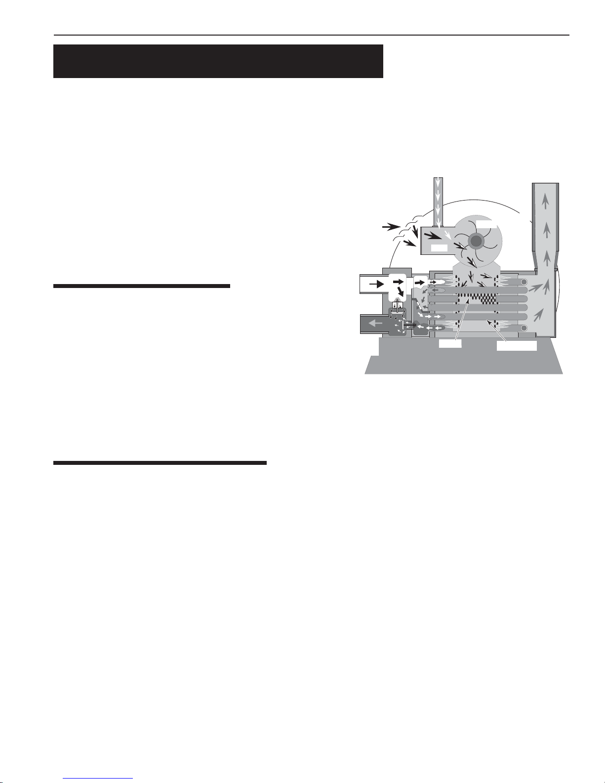
HEATER DESCRIPTION
Inlet
(Cold
Water)
Figure 8 is a diagram of the heater showing how it operates. Precisely
matched orifice plates meter the air and gas into the mixer. The blower
draws the air and gas through the mixer and forces it into the burner’s
flame holder. A sealed heat exchanger surrounds the flame holder,
discharging exhaust gases out the flue.
Outlet
(Mixed
Water)
63 mm (2 in - UK) PVC water piping connects directly to the manifold/
header on the heat exchanger using 63 mm (2 in - UK) PVC slip
unions provided with the heater. The outer manifold remains cool; no
heat sinks are required. A thermal regulator and an internal bypass
regulate the water flow through the heat exchanger to maintain the correct outlet temperature. The heater operator control
panel board assembly is located on top of the heater.
Mixer
Gas
Burner
Blower
Exhaust
Heating Coils
Figure 8.
SEQUENCE OF OPERATION
An electronic temperature sensing thermistor in the manifold adapter inlet controls the heater operation. When the inlet
water temperature drops below the temperature set on the operating control, the burner controller supplies power to the
combustion air blower through a series of safety interlocks. The interlocks consist of:
• the pressure switch (PS), which senses that the pump is running,
• the high limit switch (HLS), which opens if the heat exchanger outlet temperature goes above 55° C (131° F), and
• the air flow switch (AFS), which senses the pressure drop across the air metering orifice,
• the automatic gas shut-off (AGS) switch, which opens if the heat exchanger outlet temperature goes above 60° C (140° F).
• the inlet temperature control switch, which opens if the inlet temperature goes above 45° C (110° F).
• the stack flue sensor (SFS), which shuts down the heater if the flue gas temperature reaches 249° C (480° F).
The air flow switch (AFS) senses the pressure drop across the air metering orifice. As soon as there is suf ficient air flow,
the AFS closes, closing the circuit to the hot surface igniter (HSI), which ignites the fuel mixture. On a call for heat, the
blower and HSI are energized. In about 20 seconds, the gas valve opens and ignition occurs. The HSI then switches to a
sensing mode and monitors the flame.
The heater is equipped with a digital operating control that enables the user to pre-set the desired pool and spa water
temperatures. The control enables the user to select between pool and spa heating, and features a digital display that
indicates the water temperature.
P/N 475106 Rev. D 1/2016 MASTERTEMP™ Pool and Spa Heater Installation and User’s Guide
8 | Section
1. Installation
PUTTING THE HEATER INTO SERVICE
If the heater is installed below the level of the pool, or more than 0.6 meters (2 feet) above pool level, the pressure switch
setting should be adjusted. See “WATER PRESSURE SWITCH” in the “SAFETY CONTROLS Section” (page 5) and
the “CAUTION” under “BELOW POOL INSTALLATION Section” (see page 10).
Before putting the heater into service for the first time, follow the instructions under “BEFORE ST AR T-UP” (page 3) in
the front of this manual. Check for proper operation of the heater by following the steps under, see page 4 “OPERATION
INSTRUCTIONS.”
Notice: Damage to equipment caused by improper installation or repair will void the warranty.
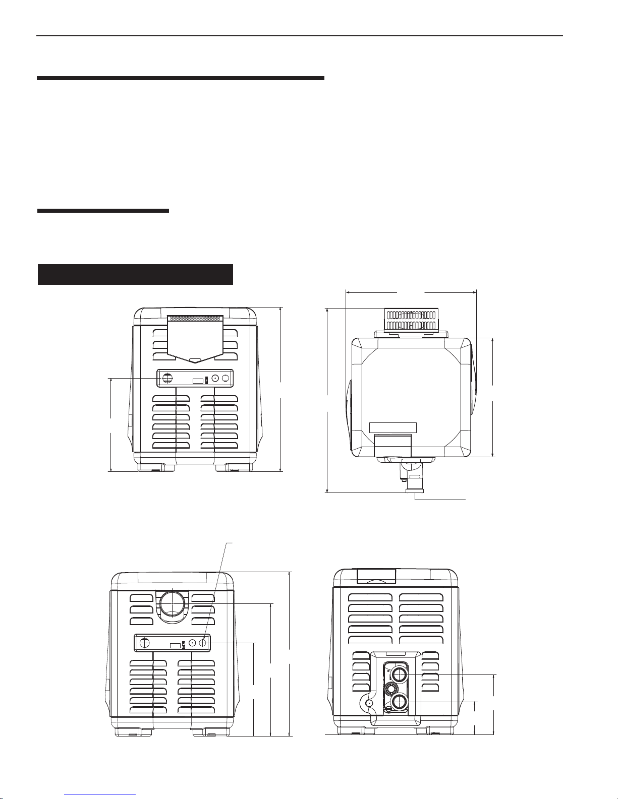
SPECIFICATIONS
These installation instructions are designed for use by qualified personnel only, trained especially for installation of this
type of heating equipment and related components. Some states require installation and repair by licensed personnel. If
this applies in your state, be sure your contractor bears the appropriate license. See Figure 9 for Outdoor Installations.
DIMENSIONS IN CENTIMETERS & INCHES
585 mm
(23")
406 mm
(16")
715 mm
(28")
ELECTRICAL
CONDUIT PORT
715 mm
(28")
578 mm
(23")
406 mm
(16")
828 mm
(31”)
533 mm
(21")
63 mm
(2" - UK)
TOPFRONT
257 mm
(10")
142 cm
(6")
Figure 9.
EXHAUST SIDE PLUMBING SIDE
MASTERTEMP™ Pool and Spa Heater Installation and User’s Guide P/N 475106 Rev. D 1/2016
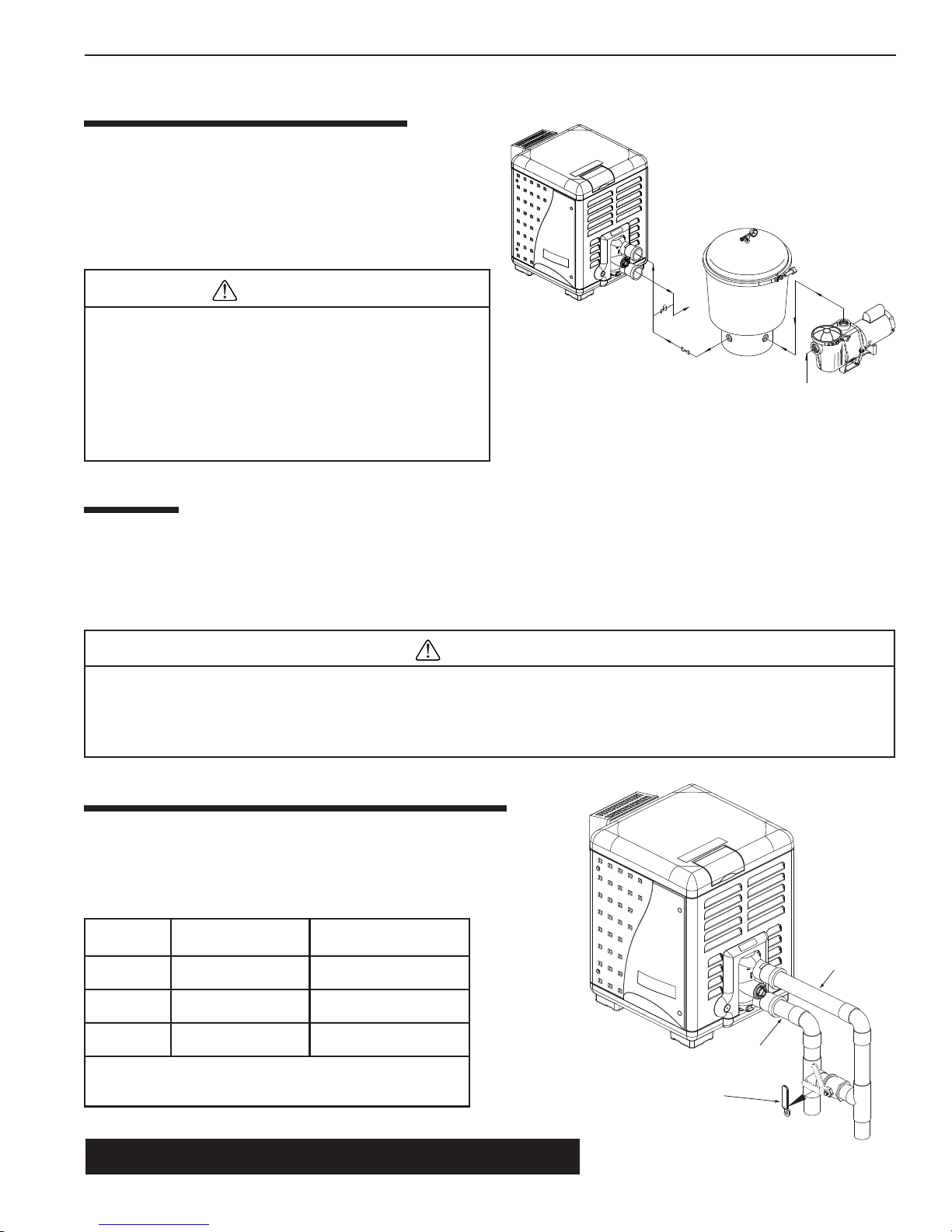
PLUMBING CONNECTIONS
The MasterTemp™ heater has the capability of direct PVC
water piping plumbing connections. A set of bulkhead fittings
is included with the MasterTemp to insure conformity with
Pentair’s recommended PVC plumbing procedure. Other
plumbing connections can be used. See Figure 11 for plumbing
connections.
Section 2. Installation
| 9
CAUTION
POOL
HEATER
Before operating the heater on a new installation, turn on
the circulation pump and bleed all the air from the filter using
Figure 10.
MANUAL
BY-PASS
TO
POOL
GATE
VALVE
FILTER
PUMP
the air relief valve on top of the filter. Water should flow
freely through the heater . Do not operate the heater unless
FROM
POOL
water in the pool/spa is at the proper level. If a manual bypass is installed, temporarily close it to insure that all air is
purged from the heater .
VALVES
When any equipment is located below the surface of the pool or spa, valves should be placed in the circulation piping
system to isolate the equipment from the pool or spa. Check valves are recommended to prevent back-siphoning. Backsiphoning is most likely to occur when the pump stops, creating a pressure-suction differential. Do NOT sanitize the pool
by putting chlorine tablets or sticks into the skimmer(s). When the pump is off, this will cause a high concentration of
chlorine to enter the heater, which could cause corrosion damage to the heat exchanger.
CAUTION
Exercise care when installing chemical feeders so as to not allow back siphoning of chemical into the heater, filters
or pump. When chemical feeders are installed in the circulation of the piping system, make sure the feeder outlet line
is down stream of the heater, and is equipped with a positive seal noncorrosive “Check Valve”, (P/N R172288),
between the feeder and heater.
MANU AL BY-PASS ( W A TER FLOW RATE)
Where the water flow rate exceeds the maximum 454 L/m, a manual
bypass should be installed and adjusted. After installing the valve, adjust
the valve to bring the flow rate within the acceptable range. Then remove
the valve handle or lock it in place to avoid tampering. See Figure 11.
ledoM)MPG(m/L.niM*)MPG(m/L.xaM
002)02(67)021(454
003)03(411)021(454
004)04(251)021(454
See page 33 for Pressure Relief Valve Installations.
P/N 475106 Rev. D 1/2016 MASTERTEMP™ Pool and Spa Heater Installation and User’s Guide
Cool water in
Warm water out
dednemmocermumixamehtdeecxetonoD*
.gnipipgnitcennocehtrofetarwolf
Table 1.
1. Set Manual By-Pass Valve.
2. Remove Handle.
Figure 11.
Outlet to pool
Inlet to heater
10 | Section
2. Installation
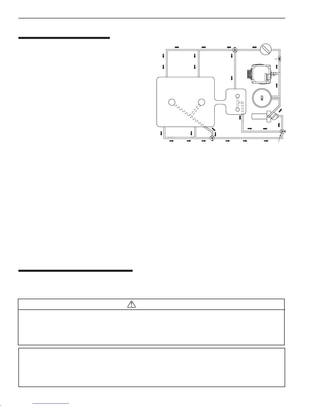
WATER CONNECTIONS
3-Way
The heater requires proper water flow and pressure for its
Valve
operation. See Figure 12 for the recommended installation.
The filter pump discharges to the filter, the filter dischar ges to
the heater, and the heater discharges directly to the pool or
spa.
A manual bypass valve should be installed across the heater
when the pump flow exceeds 454 L/m (120 GPM). See
“WATER FLOW RATE” on page 9 - Table 1 for setting of
the manual by-pass valve.
Main
Drain
Pool
Heater
Spa
Make sure that the outlet plumbing from the heater contains
no shut-off valves or other flow restrictions that could prevent
flow through the heater (except for below pool as noted below ,
or winterizing valves where needed). T o switch flow between
the pool and spa, use a diverter valve. Do not use any valve
that can shut off the flow. Do not use a shut-off valve to
isolate the heater unless it is below the level of the pool or spa.
From Pool
3-Way
Valve
Figure 12.
Install the chemical feeder downstream of the heater. Install
a chemical resistant one-way check valve between the heater and the chemical feeder to prevent back-siphoning through
the heater when the pump is off.
NOTICE: If the heater is plumbed in backwards, it will cycle continuously. Make sure piping from filter is not reversed
when installing heater.
Connect the heater directly to 63 mm (2 in - UK) PVC pipe, using the integral unions provided. Heat sinks are not
required. The low thermal mass of the heater will prevent overheating of the piping connected to the pump even if the
heater shuts down unexpectedly . Occasionally a two-speed pump will not develop enough pressure on the low speed to
operate the heater. In this case, run the pump at high speed only to operate the heater . If this does not solve the problem, do
not try to run the heater. Instead, correct the installation.
Do not operate the heater while an automatic pool cleaner is also operating. If the circulation pump suction is plugged (for
example by leaves), there may not be adequate flow to the heater. Do not rely on the pressure switch in this case.
If European Standard Codes of Practice require the installation of a pressure relief valve (PRV), see page 33 for
“PRESSURE RELIEF VALVE INSTRUCTIONS”.
Chlorinator
Check Valve
Filter
Pump
3-Way
Valve
BELO W POOL INST ALLA TION
If the heater is below water level, the pressure switch must be adjusted. This adjustment must be done by a qualified
service technician.
See following CAUTION before installation.
BELOW OR ABOVE POOL INSTALLATION
The Water Pressure Relief V alve Switch is set in the factory at 0.20 bar (3.00 psi). This setting is for a heater installed at pool
level. If the heater is to be installed more than 0.3 m above or below, the water pressure switch must be adjusted by a
qualified service technician. See page 33, Figure 32.
If the heater is installed more than 1.5 m above the pool or more than 1.2 m below the pool level, you will be beyond the
limits of the pressure switch and a flow switch must be installed. Locate and install the flow switch externally on the outlet
piping from the heater , as close as possible to the heater. Connect the flow switch wires in place of the water pressure
switch wires.
MASTERTEMP™ Pool and Spa Heater Installation and User’s Guide P/N 475106 Rev. D 1/2016
CAUTION
FLOW SWITCH INSTALLATION
Section 2. Installation
| 11
GAS CONNECTIONS
GAS LINE INST ALLA TIONS
The gas supply must be installed in accordance with the Eur opean S tandard Codes of Practice for gas installation as applicable and
all applicable local codes.
THE MASTERTEMP HEATER IS INTENDED FOR INSTALLATION WITH A METERED GAS PRESSURE REGULATOR.
Before installing the gas line, be sure to check which gas the heater has been designed to burn. This is important because different
types of gas require different gas pipe sizes. The rating plate on the heater will indicate which gas the heater is designed to burn.
T able 2 below shows the recommended gas inlet pipe sizes required for the distance from the gas meter to the heater . The table is
for G20 and G25 at a specific gravity of .65 and G31 at a specific gravity of 1.55.
When sizing gas lines, calculate 0.9 additional meters of straight pipe for every elbow used. When installing the gas line, avoid getting
dirt, grease or other foreign material in the pipe as this may cause damage to the gas valve, which may result in heater failure.
The gas meter should be checked to make sur
be used on the same meter. Insufficient gas supply will cause the heater to operate below its designed performance or not at
all. The gas line from the meter will usually be of a larger size than the gas valve supplied with the heater. Therefore a
reduction of the connecting gas pipe will be necessary. Make this reduction as close to the heater as possible. If the gas
pressure is not adjusted to the correct working pressure, the heater will be over gassed and cause serious damage within
minutes. This damage is not covered under the heater warranty.
Install a manual shut-off valve that conforms with
located outside the heater panels, see Figure 13. Do not use a restrictive gas cock.
The heater and any other gas appliances must be disconnected from the gas supply piping system during any pressure testing on that
system, (greater than 6.0 kPa). The heater and its gas connection must be leak tested before placing the heater in operation. Do not
use flame to test the gas line. Use soapy water or another nonflammable method.
e that it will supply enough gas to the heater and any other appliances that may
European Standard Codes of Practice, and a sediment trap/drip leg and union
NOTE
A manual main shut-off valv e must be installed externally to the heater .
WARNING
DO NOT INSTALL THE GAS LINE UNION INSIDE THE HEA TER CABINET. THIS WILL VOID YOUR WARRANTY.
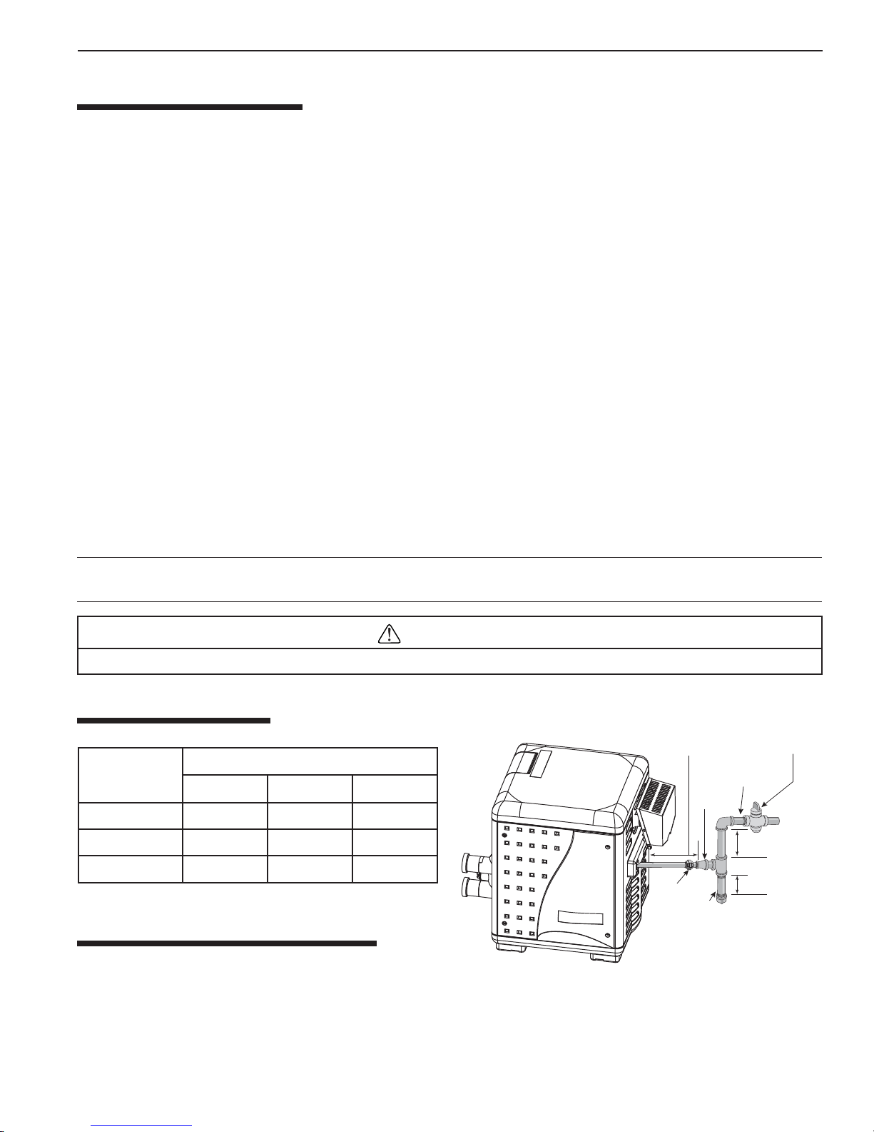
GAS PIPE SIZING
Table 2.
reteMehtmorfecnatsiD
eziSretaeH
m51ot0m03ot61m06ot13
002mm52mm23mm23
003mm23mm23mm04
004mm23mm04mm05
SEDIMENT TRAP/DRIP LEG
Install a sediment trap/drip leg and union located outside the
heater panels in accordance with European S tandard Codes of Practice requirements. Do not use a restrictive gas cock.
The sediment trap/drip leg shall be either a tee fitting with a capped nipple in the bottom outlet which can be removed for
cleaning, as illustrated in Figure 14, or an other device recognized as an effective sediment trap/drip leg. All gas piping
should be tested after installation in accordance with local codes.
45-60 cm x 3/4 in
(18–24" of 3/4")
Gas line from
Valve
2.54 cm (1") Dia. or larger
(See "Recommended
Bell
Reducer
Union
Sediment
Trap/Drip Leg
Pipe Sizes" Chart
At least 23 cm (9")
At least 8 cm (3")
Figure 13.
Manual
Shut-off
Valve
)
P/N 475106 Rev. D 1/2016 MASTERTEMP™ Pool and Spa Heater Installation and User’s Guide
12 | Section
2. Installation
TESTING GAS LEAKS AND GAS PRESSURE
THE MASTERTEMP HEA TER IS INTENDED FOR INST ALLA TION WITH A METERED GAS PRESSURE REGULA T OR.
Before operating the heater, the heater and its gas connections must be leak tested. Do NOT use an open flame to test
for leaks. Test all gas connections for leaks with soapy water.
The gas valve must be completely disconnected from the gas supply piping system during any pressure testing of that
system at test pressures in excess of 6.0 kPa (60 mbar).
TESTING THE GAS PRESSURE THROUGH THE COMBINATION GAS CONTROL VALVE
WARNING
Risk of fire and explosion. Alteration, service, or maintenance of the Combination Gas Control Valve can lead to fire or
explosion, causing loss of life, personal injury, and/or property damage.
VALVE.
These instructions are for the use of qualified service technicians only!
1. Shut off the gas supply to the heater.
2. Loosen the small screw inside the pressure tap as shown in Figure 14.
Connect the manometer hose.
3.
4. Open the gas supply to the heater.
5. Turn on the heater.
6. Take the gas pressure reading.
7. Turn off the heater.
8. Shut off the gas supply to the heater.
9. Disconnect the manometer hose.
10. Tighten the small screw inside the pressure tap.
11. Open the gas supply to the heater.
12 Verify that the seal connection in the pressure tap is closed by testing
for leaks with soapy water.
Note: If the pressure reading is out of range, (see Table 3), regulate the
incoming gas pressure.
INLET GAS PRESSURE REQUIREMENTS
noitpircseDepyTerusserPylppuSsaG
:ETON ehtdeecxetonoD.tnemtsujdatupnirofdevorppaeulavmuminimehT
Table 3.
saGlarutaN
saGenaporP
.erusserpylppusmumixam
LLE2;iE2,sE2;N2;+E2;H2
)52G/02G(
)13G(P3rabm73
.gnitareposiretaehelihwnekatebtsumsgnidaerllA sgnidaerrostnemtsujdaynA
.smelborpecnamrofrepnitluserlliwffosiretaehelihwedam
rabm52-02
DO NOT ATTEMPT TO ADJUST THE GAS CONTROL
Lightly loosen the
small screw inside the pressure tap,
and attach/connect the manometer hose.
Figure 14.
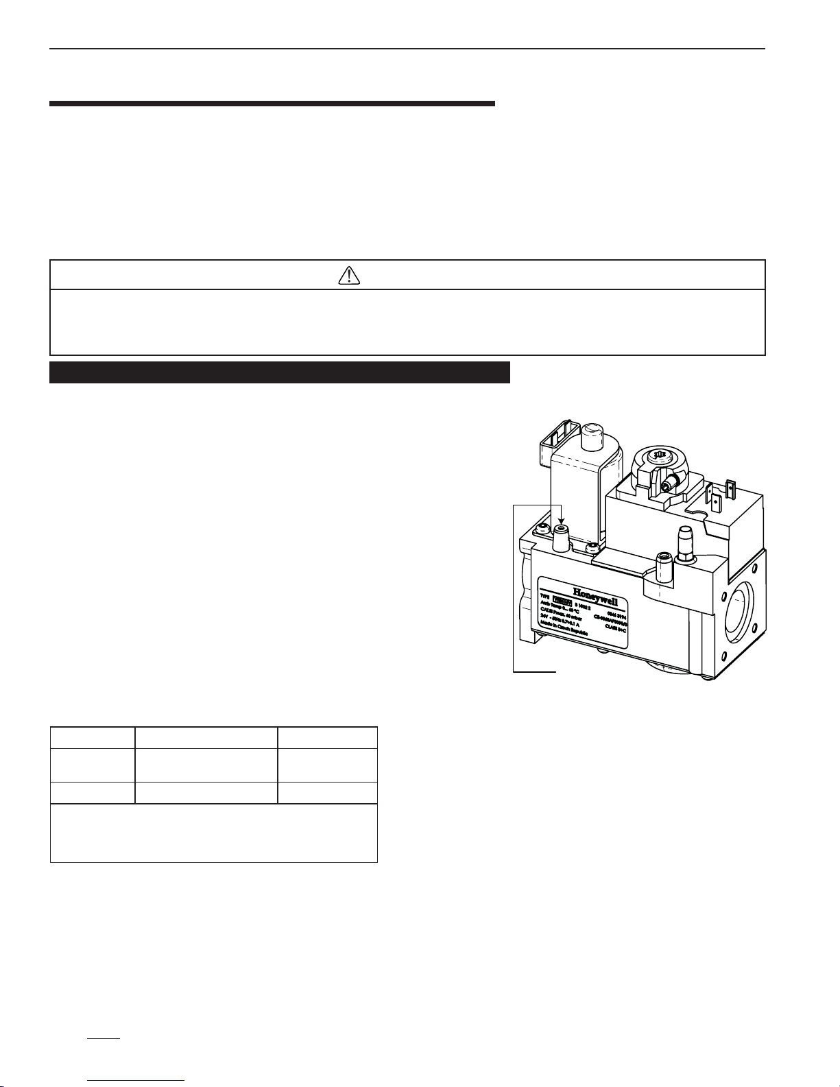
This appliance is equipped with an unconventional gas control valve that is factory set with a manifold pressure of
1.1 ± 0.5 mbar. Installation or service must be performed by a qualified installer, service agency, or the gas supplier . If
this control valve is replaced, it must be replaced with an identical control. The combination gas valve incorporates dual
shut-off valves and a negative-pressure regulator. For proper operation, the regulated pressure at the outlet manifold of
the valve must be 1.1 ± 0.5 mbar below the reference pressure at the blower mixer inlet, and the gas valve ‘VENT’
tap must be connected to the end cap air orifice as shown in Figure 14. DO NOT attempt to adjust the gas input by
adjusting the regulator setting. The correct gas regulator setting is required to maintain proper combustion and
must NOT be altered.
MASTERTEMP™ Pool and Spa Heater Installation and User’s Guide P/N 475106 Rev. D 1/2016
Lead
Anchor
For Heater mounting
bolts and clamps,
purchase separately
Bolt Down Bracket Kit,
Part No.
460738.
Section 2. Installation
| 13
OUTDOOR INSTALLATION
For heaters located outdoors, using the built-in stackless venting system.
DANGER
CARBON MONOXIDE GAS IS DEADL Y – Exhaust from this pool heater contains carbon monoxide, a dangerous, poisonous gas you
cannot see or smell. Symptoms of carbon monoxide exposure or poisoning include dizziness, headache, nausea, weakness, sleepiness,
muscular twitching, vomiting and inability to think clearly . IF YOU EXPERIENCE ANY OF THE ABOVE SYMPTOMS, IMMEDIATELY
TURN OFF THE POOL HEATER, LEAVE THE VICINITY OF THE POOL OR SPA AND GET INTO FRESH AIR IMMEDIATELY.
THE POOL HEATER MUST BE THOROUGHLY TESTED BY A GAS PROFESSIONAL BEFORE RESUMING OPERA TION.
EXCESSIVE CARBON MONOXIDE EXPOSURE CAN CAUSE BRAIN DAMAGE OR DEATH.
WARNING
Risk of explosion if a unit burning G31 is installed in a pit or other low spot. G31 is heavier than air . Do not install the heater
using propane in pits or other locations where gas might collect. Consult the European Standard Codes of Practice building code
officials to determine installation requirements and specific installation restrictions of the heater relative to propane storage tanks and
filling equipment. Installation must meet the requirements for the Standard for the Storage and Handling of Liquid Petroleum Gases.
Consult local codes and fire protection authorities about specific installation restrictions.
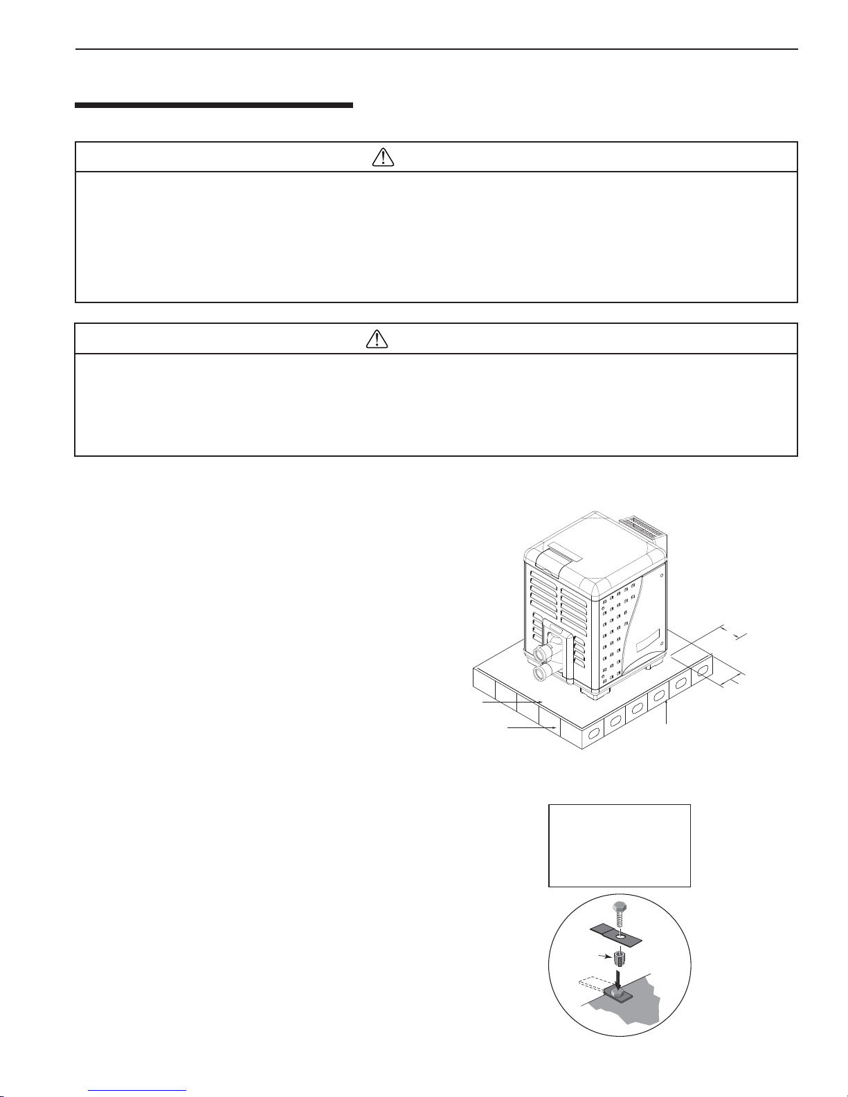
Locate the heater in an open, unroofed area and on a level surface that is protected from drainage or run-off. Install the
heater in an area where leaves or other debris will not collect
on or around the heater.
It is recommended that a non-combustible base be a platform
under the heater constructed of hollow masonry blocks, not
less than 100 mm (4 in) thick (laid with ends unsealed and
joints matched for air circulation). Cover blocks with 0.75
mm (0.03 in) minimum galvanized sheet metal, see Figure 15.
T
o avoid damage to the electronic components in the heater,
take care to prevent prolonged exposure to driving sources of
water (such as lawn sprinklers, heavy roof runoff, hoses, etc.).
Avoid operation in persistent, extreme, moist or salty
environments.
In extreme weather, shut down the heater and disconnect the
power to it until the weather has moderated. In areas subject
to hurricanes or very high winds, purchase the Bolt Down
Bracket Kit, P/N 460738, see Figure 16.
BASE FOR USE ON
COMBUSTIBLE FLOORS
150 mm
(6 in) Min.
150 mm
SHEET
METAL
BLOCKS
Hollow masonry blocks, not less than 100 mm (4 in) thick, (laid with ends unsealed and joints
matched for air circulation). Cover blocks with 0.75 mm (0.03 in) minimum galvanized sheet metal.
Figure 15.
.
Masonary blocks
100 mm (4 in) thick minimum
(6 in) Min.
P/N 475106 Rev. D 1/2016 MASTERTEMP™ Pool and Spa Heater Installation and User’s Guide
Figure 16.
14 | Section
2. Installation
HEA TER CLEARANCES – OUTDOOR
IMPORTANT!
• In an outdoor installation it is important to ensure water is diverted
from overhanging eves with a pr oper gutter/drainage system. The heater
must be set on a level foundation for proper drainage.
• This unit shall not be operated outdoors at temperatures below -7o C.
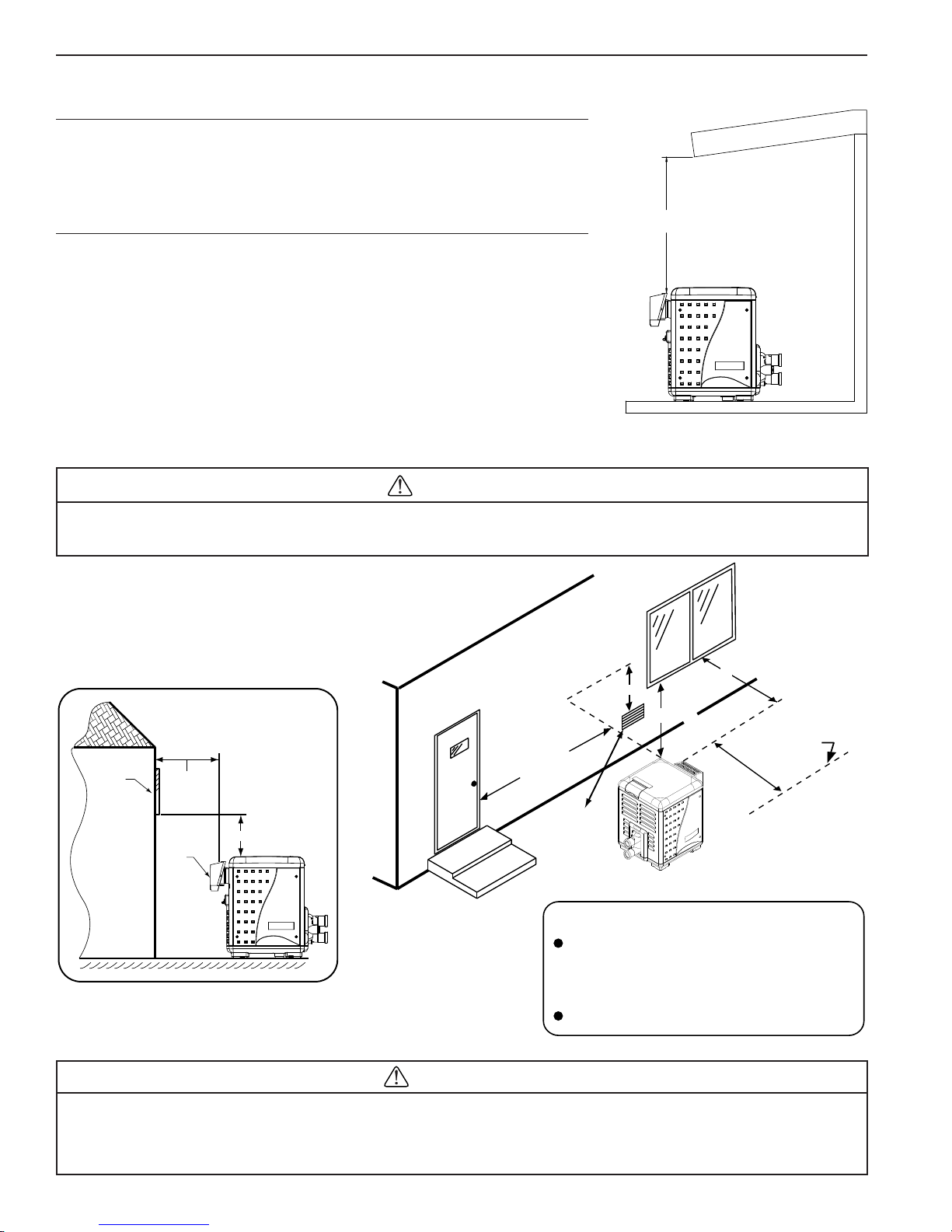
If the heater is located under a roof or deck overhang, there must be at least
1 meter (3 ft.) of clearance between the bottom of the overhang and the top of
the heater exhaust vent, see Figure 17. If the heater is under a roof or deck
overhang, the space around the heater must be open on three sides.
For minimum exhaust vent clearances for building openings, see below Figure 18.
Orient the heater for convenient access to the water connections and the gas
and electrical connections.
Check the European Standard Codes of Practice for setback (property line)
requirements.
CAUTION
1 meter (3 ft.) or more
Figure 17.
If installing the heater next to or near an air conditioning unit or a heat pump, allow a minimum of 92 cm
(36 in.) between the air conditioning unit and the heater.
OUTDOOR INSTALLATION
VENTING GUIDELINES
1500 mm
1500 mm
Window
Building
1500 mm
Exhaust Grill
(Vent)
SIDE VIEW
1500 mm
1500 mm
Force
Air Inlet
Vent T ermination:
Must be installed at least 1500 mm away from
the building wall openings, and at the following
distances away from any door, window, or
gravity air inlet.
1500 mm
Property Line
Check local building codes
for setback requirements.
Figure 18.
Risk of fire and explosion. Do not spray aerosols in the vicinity of the heater while it is in operation. Chemicals
should not be stored near the heater installation. Combustion air can be contaminated by corrosive chemical fumes
which can damage the heater and will void the warranty.
MASTERTEMP™ Pool and Spa Heater Installation and User’s Guide P/N 475106 Rev. D 1/2016
The heater must also have no obstructions above it.
WARNING
Section 2. Installation
| 15
INDOOR VENTING — General Requirements
If you are considering connecting this heater to a pre-existing vent system, make sure that the vent system meets the
appropriate venting requirements as given in this manual on pages 15-20. If not, replace the vent system. DO NOT use a
draft hood with this heater. The MasterTemp heaters are capable of a 270-degree discharge rotation and with a vent gas
temperature less than 204° C (400° F). The total length of the horizontal run must not exceed the length that is listed in
T able 5 on page 17.
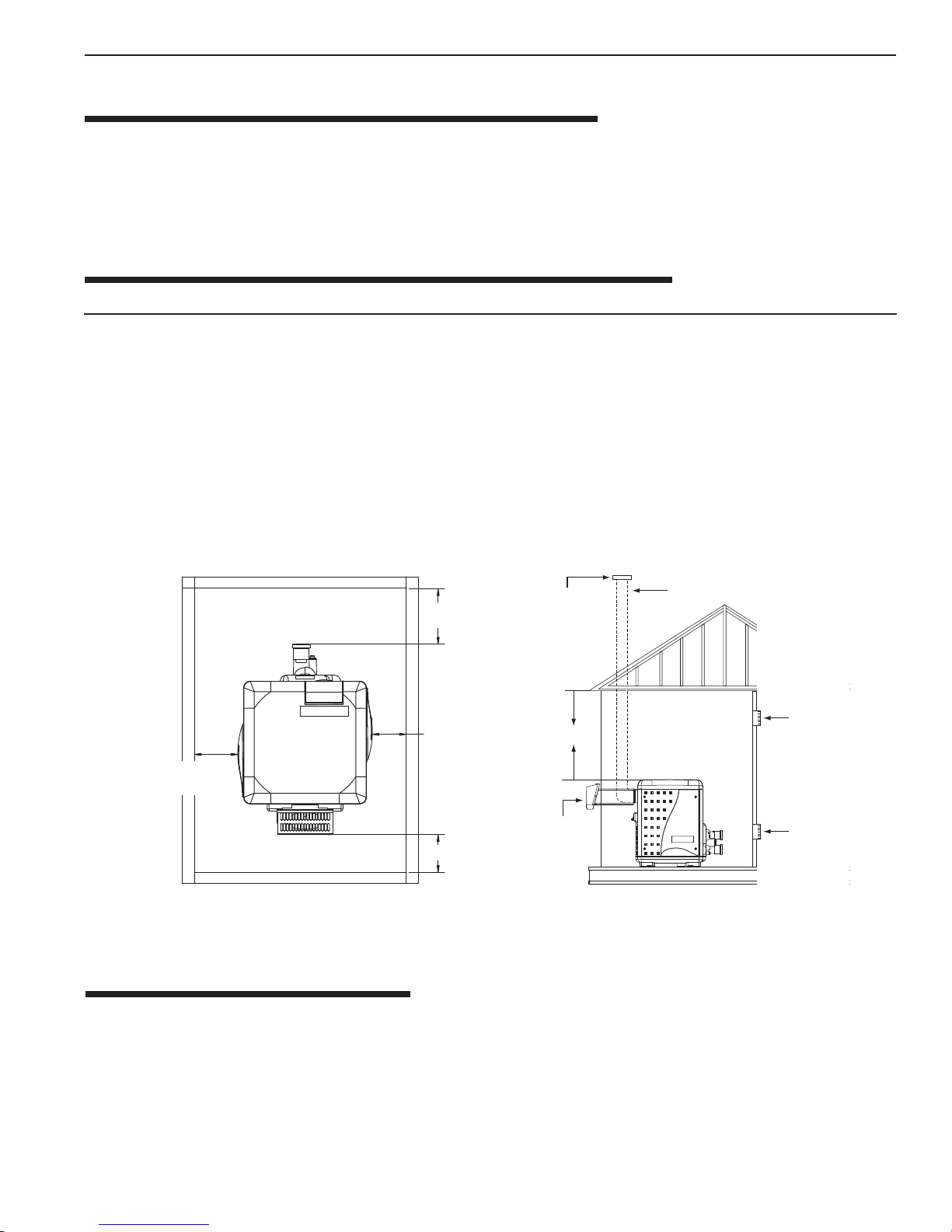
HEATER CLEARANCES — General Requirements
INDOOR INST ALLATION AND OUTDOOR SHEL TER
The following clearances must be maintained from the nearest walls: (See Figure 19, 20 & 21)
TOP ................................... 15 cm (6 in) HEADER SIDE ........................... 15 cm (6 in.)
EXHAUST SIDE ............... 15 cm (6 in.) DOOR PANELS* .......................... 15 cm (6 in.)
Note (*) For service access it is advisable to allow for sufficient clearance on at least one door panel. The heater is
designed for installation on combustible flooring. For installation on carpeting, the heater must be mounted on a metal or
wood panel that extends at least 10 cm (4 in) beyond the base of the heater. Note: Wall sensitive to heat
(for example wood), must be protected by a suitable insulation. If the heater is installed in a closet or alcove, the entire
floor shall be covered by the panel. On an outdoor shelter installation, the exhaust discharges into a vent pipe. Orient the
heater so that the vent pipe does not interfere with adjustment of the operating controls. The control panel located on the
top panel can be rotated to any of the three sides of the heater for easy access. However, the control panel must not be
located on the side where the vent is located.
Chimney or Gas Vent
Heater
Outlet Air
Opening
Inlet Air
Opening
Figure 19.
(*) For service access, it is advisable to allow for
sufficient clearance on at least one door panel.
15 cm*
(6 in)
15 cm
(6 in)
15 cm
(6 in)
15 cm
(6 in)
*
*
*
Vent Cap and
Riser Furnished
by Installer
Figure 20.
15 cm
(6 in)
Side
Wall V ent
OUTSIDE VENT COVER REMOVAL
THE HEA TER IS SUPPLIED FR OM THE F A CTORY WITH A B UILT-IN STA CKLESS OUTSIDE VENT FOR OUTDOOR INSTALLATION. REMO VE THE OUTSIDE VENT COVER FOR OUTDOOR SHEL TER INSTALLATION.
COMBUSTION AIR SUPPLY
For indoor installation, the heater location must provide sufficient air supply for proper combustion and ventilation of the
surrounding are in accordance with European Standard Codes of Practice. The minimum requirements for the air supply
specify that the room in which a heater is installed should be provided with two permanent air supply openings; one
within 30 cm (12 in) of the ceiling, the other within 30 cm (12in) of the floor for combustion air, in accordance with the
European Standard Codes of Practice as applicable, and any local codes that may apply . These openings shall directly, or
through duct, connect to outdoor air.
Pentair Water Pool and Spa, Inc. does not recommend indoor installations that do not provide combustion
air from outside the building. (Continue on next page)
P/N 475106 Rev. D 1/2016 MASTERTEMP™ Pool and Spa Heater Installation and User’s Guide
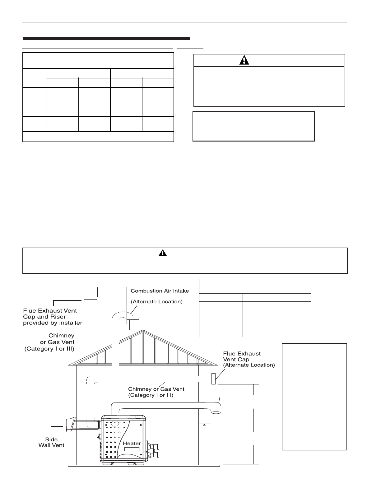
16 | Section
2. Installation
COMBUSTION AIR SUPPLY (CONTINUED)
Air Supply Requirements Guide for MasterTemp™ Heaters
Minimum Net Free Open Area for Each Opening*
(Square Inches/Centimeters)
Model
200
300
400
*
Area indicated is for one of two openings; one at floor level and one at the ceiling.
All Air From Inside Building All Air From Outside Building
Combustion Vent Combustion Vent
200 sq. in.
1290 cm
325 sq. in.
2097 cm
400 sq. in.
2580 cm
2
2
2
.
200 sq. in.
1290 cm
325 sq. in.
2097 cm
400 sq. in.
2580 cm
2
2
2
50 sq. in.
323 cm
80 sq. in.
516 cm
100 sq. in.
645 cm
50 sq. in.
2
323 cm
80 sq. in.
2
516 cm
100 sq. in.
2
645 cm
Chemicals should not be stored near the heater
installation. Combustion air can be contaminated by
2
corrosive chemical fumes which can void the
warranty.
2
NOTE *: Vent must be at least 2.4 m (8 ft) away from
2
nearest vertical surface. Vents extending 1.5 m (5 ft)
or more above the roof must be braced or guyed.
Consult your local code officials for detailed information.
CAUTION
Table 4.
VENT INSTALLATION –
INDOOR INSTALLATION OR OUTDOOR SHELTER
FLUEING MUST BE IN ACCORDANCE WITH EUROPEAN ST ANDARD CODES OF PRACTICE. Always vent
the heater to the outdoors (see above
NOTE*). Vent the heater vertically using double wall vent connector pipe. Locate the
heater so as to minimize the length of horizontal venting and the number of vent elbows required. Horizontal vent runs
must slope to allow exhaust condensate to drain and it is recommended to have a condensate drain as described in the
venting installation instructions.
Direct Air Intake Duct with 76 mm (3 in - UK) PVC Pipe (Indoor Installation)
For indoor heater installations where combustion air supply might be insufficient, the MasterTemp Heater is certified for a direct air
intake duct using a 76 mm (3 in - UK) PVC pipe (Pentair P/N 461031). If outside air is drawn through the PVC duct directly into the
heater, the PVC pipe can be installed in accordance with the f ollowing requirements: The air intake opening MUST be installed at least
30.5 cm (12 in.) above the roof line or normal snow lev els for free air flo w . The Category I or III exhaust vent termination cap must hav e
at least 1.8 m (6 ft.) minimum vertical clearance from air intake duct. (See Figure 21 below).
WARNING! WARNING!
WARNING!
WARNING! WARNING!
DO NOT USE PVC PIPE FOR FLUE EXHAUST VENT. FLUE EXHAUST VENT TEMPERATURES CAN BE IN EXCESS OF 204° C.
FLUE EXHAUST VENT MUST BE CATEGORY I or CATEGORY III METAL VENT.
914 mm
min. (36”)
76 mm (3”) PVC pipe
Combustion PVC Air Intake 76 mm (3”) Pipe
(Vertical or Horizontal)
No. of 90° Elbows
Maximum Length in Meters (Ft)
0 21 M (70 ft.)
1 18 M (58 ft.)
2 14 M (46 ft.)
305 mm min. (12”)
3 10 M (34 ft.)
4 7 M (22 ft.)
NOTE
Each 90-degree elbow
reduces the maximum
horizontal PVC air
intake duct run by 3.6
Combustion Air Intake
76 mm (3”) PVC pipe
914 mm
min. (36”)
m (12 ft.) and each 45degree elbow in the
PVC air intake duct
run reduces the
maximum run by 1.8
m (6 ft.). See the Table
above for the
152 mm
min. (6”)
305 mm
min. (12”)
maximum lengths
using 90-degree
elbows.
Figure 21.
MASTERTEMP™ Pool and Spa Heater Installation and User’s Guide P/N 475106 Rev. D 1/2016
Section 2. Installation
| 17
HORIZONT AL OR VER TICAL VENTING - USING SINGLE-W ALL STAINLESS GAS
VENT
V ent the heater either horizontally or vertically using an optional vent adapter of the 150 (6 in) or 102 mm (4 in) special gas
approved stainless steel vent pipes. Installation must be in accordance with all local codes and ordinances/or the latest
edition of the local code standards and/or local codes. The heater, when installed, must be electrically grounded and bonded
in accordance with local codes. Do not use a draft hood with this heater . Install the vent according to the vent manufacturer’s
detailed instructions. Note: Keep a 150 mm (6 in) minimum clearance between the vent pipe and combustible surfaces.
Follow the vent manufacturer’s instructions and code requirements. Do
not place any insulating materials around the vent or inside the required
clear air space surrounding the vent. See T able 5 for maximum permissible
vent lengths.
(SEE FIGURE 22, 23, & 24
ON PAGE 19
)
)ni4(mm201ro).ni6(mm251
tneVsaGlaicepS
)latnoziroHrolacitreV(
*
NOTE
The allowable vent runs for each vent pipe diameter are
different and can not be exceeded.
swoblE°09fo.oN
0).tf83(m6.11
nihtgneLmumixaM
)M(teeF
Each 90-degree elbow reduces the maximum horizontal vent
run by 3.6 m (12 feet) and each 45-degree elbow in the vent run
1).tf62(m8
reduces the maximum vent run by 1.8 m (6 feet). See the
Table 5 for the maximum v ent lengths using 90° elbows.
*
.niardotetasnednoc
T able 5.
niro).tf1(mm503sihtgneltnevmuminiM
,noitcurtsnis’rerutcafunamtnevhtiwecnadrocca
stnevlatnoziroH.sedoclanoitandnalacoldna
aeriuqertonodhtgnelnisselro)tf3(m1
ehtdrawotnwodepolstsumtub,eetetasnednoc
wollaot).tf/ni4/1(retemehtotmc2tateltuo
NOTE
It is recommended that vent runs over 5.4 m (18 feet) may need to be insulated to reduce condensation related
problems and/or the use of a condensate trap in the vent run close to the heater may be necessary in certain
installations such as cold climates. Horizontal vents 1 m (3 ft) or less in length do not require a condensate tee.
The MasterTemp heater is suitable for through-the-wall venting.
Flue gases may escape into the dwelling with any cracks or loose joints in the vent pipe, or improper vent installation.
The vent pipe must be of a sealed-seam construction and for operating temperatures less than 204° C (400°F). Vent pipe
construction will be according to local code standards, approved non-corrosive material, such as stainless steel. A condensate
trap may be needed. The use of “Approved” thimbles, roof jacks and/or side vent terminals are required; and the proper
clearances to combustible materials must be maintained in accordance with type of vent pipe employed—in the absence of
a clearance recommendation by the vent pipe manufacturer, the requirements of the Uniform Mechanical Code should be
met. The ventilation air requirements for the MasterTemp heater can be found on page 18. It is recommended that vent
runs over 5.4 M (18 f t) may need to be insulated to reduce condensation related problems and/or the use of a condensate trap in the
vent run close to the heater may be necessary in certain installations such as cold climates. Horizontal vents 1 M (3 ft) or less in
length do not require a condensate tee. The MasterTemp heater is suitable for through-the-wall venting.
After installation, installer must check for correct and safe operation of the heater .
P/N 475106 Rev. D 1/2016 MASTERTEMP™ Pool and Spa Heater Installation and User’s Guide
NOTE
2. Installation
18 | Section
CONNECTING SINGLE-WALL STAINLESS STEEL VENT TO THE HEATER
Metallic:
1. Order an optional appliance adapter kit,
- Part No. 77707-0086 for Saf-T Vent® or Saf-T Vent® CI. - Part No. 77707-0087 for Z-Vent. (UK only). To order
this optional adapter kit, please contact Pentair sales at Industriepark, Wolfstee, Toekomstlaan 30, 2200 Herentals Belgium.
2. Remove the outside vent cover.
3. Install the Appliance Adapter in the Vent Body of the heater (located under the outside V ent Cover). Before connecting
the Appliance Adapter to the V ent Body , wet a clean cloth or paper towel with isopropyl alcohol (rubbing alcohol) and
vigorously wipe the socket of the Vent Body. Immediately wipe the cleaned surfaces dry with a clean cloth or paper
towel. Repeat for the exterior of the heater end of the Appliance Adapter. Attach the appliance adapter to the vent
body using the adhesive specified by the vent manufacturer, following the vent manufacturer’ s instructions.
(Pentair offers optional appliance adapter kits, call our Customer Service dept.):
WARNING
Risk of carbon monoxide poisoning if adapter is improperly attached. Mechanical connections (such as screws) can
cause cracking and leaks in the adapter. Do NOT drill holes or use screws to connect the appliance adapter to the heater vent
body. Attach with manufacturer’s specified adhesive.
WARNING
Risk of fire or asphyxiation if vent is not assembled according to manufacturer’s instructions or if vent parts from
different manufacturers are mixed. Vent parts from different manufacturers ARE NOT interchangeable. Mixing parts from
more than one manufacturer may cause leaks or damage to vent. When installing a vent, pick one manufacturer and be sure
that all vent parts come from that manufacturer and are specified by the manufacturer for your system. Follow manufacturer’s
instructions and local code requirements carefully during assembly and installation.
4. Install vent pipe so that it can expand and contract freely as the temperature changes. Support the vent pipe according
to applicable codes and vent manufacturer’s instructions. Pipe support must allow the vent pipe free movement out
and back, from side to side, or up and down as necessary, without putting a strain on the heater or vent body. It is
recommended to slope the horizontal pipe down to condensate trap at least 2cm/m (1/4 in per foot). Install “Approved”
condensate drains at low points where condensate might collect. Plumb condensate drains to a drain through hard
piping or high-temperature tubing such as silicone rubber or EPDM rubber – do not use vinyl or other low temperature
tubing. Follow drain manufacturer’s installation instructions.
5. Use an “Approved” fire stop for floor and ceiling penetrations. Use an “Approved” thimble for wall penetrations. Use
an “Approved” roof flashing, roof jack, or roof thimble for all roof penetrations. Do not fill the space around the vent
(that is, the clear air space in the thimble or fire stop) with insulation. The roof opening must be located so that the vent
is vertical.
MASTERTEMP™ Pool and Spa Heater Installation and User’s Guide P/N 475106 Rev. D 1/2016
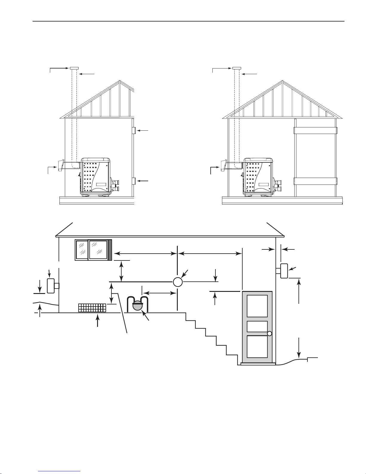
Section 2. Installation
6. Vent Termination – V ertical (See Figure 22, 23, & 24), for height of vent termination above the roof. Use an
“Approved” vent terminal specified by local and national codes and your manufacturer’s instructions. A roof
termination must be vertical.
7. Make sure entire installation is sealed according to approved standard.
| 19
Vent Cap and
Riser Furnished
by Installer
Side
Wall V ent
Figure 22
Vent
Termination
Chimney or Gas Vent
Heater
1.2 m (4 ft) Min.
Outlet Air
Opening
Inlet Air
Opening
Vent Cap and
Riser Furnished
by Installer
Wall V ent
1.2 m (4 ft) min.1.2 m (4 ft) min.
Vent
Termination
Side
Figure 23.
Chimney or Gas Vent
Heater
Outlet Air Opening
Inlet Air Opening
Max. 305 mm (12 in)
Min. 76 mm (3 in)
Vent
Termination
1.2 m
0.3 m (1 ft) min.
(4 ft)
0.3 m (1 ft) minimum
above snow or
finished grade
(whichever is
higher)
Figure 24.
Forced Air
Inlet
min.
Gas Meter
76 mm (3 in) minimum clearance ifr
horizontal distance to
exhaust opening is less
than 3 m (11 ft).
At least 2 m (7 ft)
above grade
adjacent
to public
walkways
8. Vent Termination – Horizontal
The terminal must be located (See Figure 23):
• at least 76 mm (3 in) and at most 305 mm (12 in) out from the wall (see Figure 24), following the vent manufacturer’s
instructions
• at least 304 mm (12 in) above finished grade or the normally expected snow accumulation level, whichever is higher
• at least 1.2 M (4 ft) below or horizontally from, or 0.3 M (1 ft) above, any doors or windows or gravity air inlet to a
building
• at least 0.9 M (3 ft) above any forced air inlet located within 3 M (10 ft)
• at least 1.2 M (4 ft) horizontally from electric meters, gas meters, regulators and relief equipment
• at least 2.1M (7 ft) above grade adjacent to walkways or similar traffic areas
P/N 475106 Rev. D 1/2016 MASTERTEMP™ Pool and Spa Heater Installation and User’s Guide
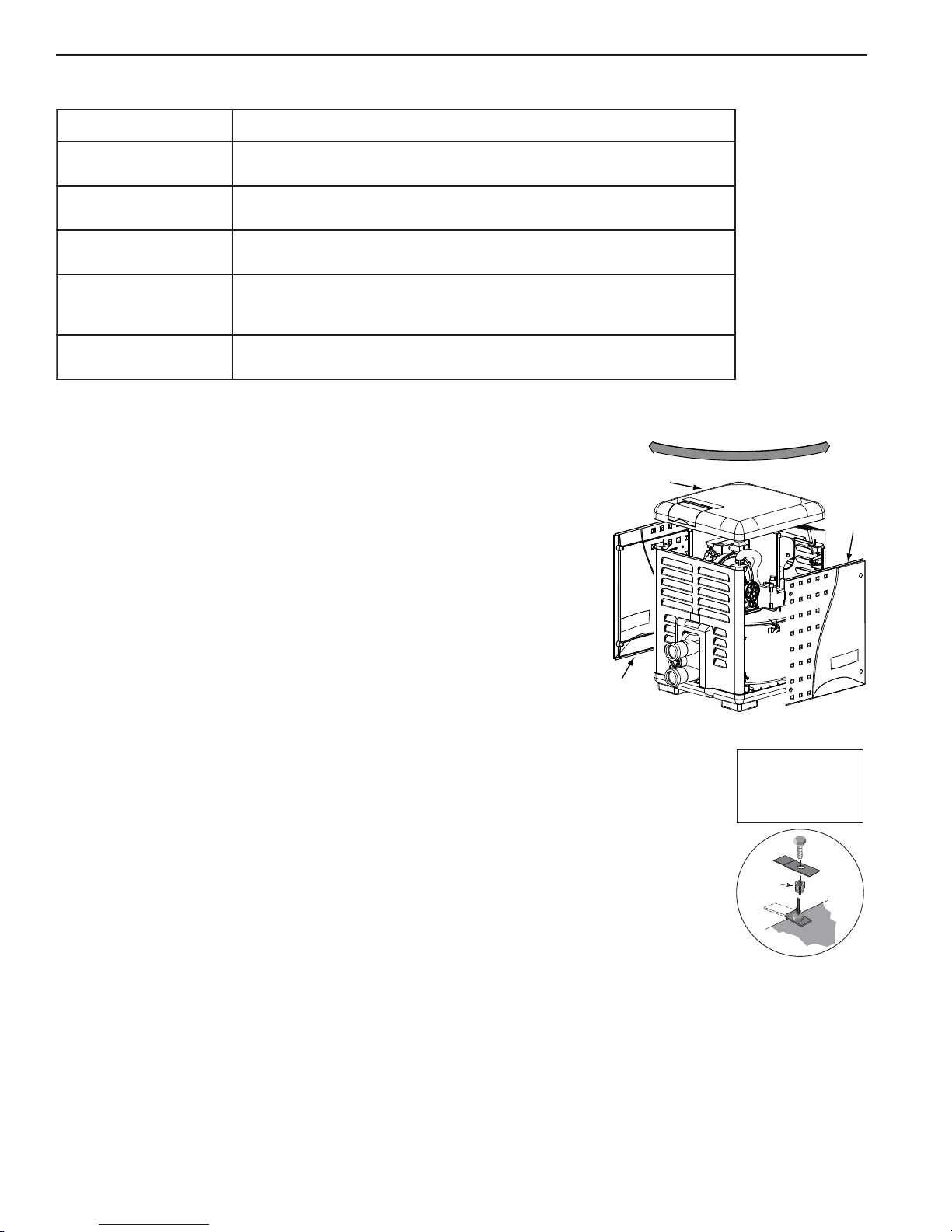
s
2. Installation
20 | Section
Corrosive V apors and Possible Causes
aerAstnanimatnoCylekiL
gnimmiwsdetanirolhC
sapsdnasloop
dnanoitcurtsnocweN
saeragniledomer
srolrapytuaeB
rostnalpnoitaregirfeR
gnihsiniflairtsudnisuoirav
stnalpgnissecorpdna
yrdnualdnagninaelcyrD
saera
.snobracoroulf
.sevisehdanoitcurtsnoc,stnemecdnaseulg,sdica,stnaregirfeR
.edirolhcmuidosromuiclac,enirolhcgniniatnoc
CONTROL PANEL INDEXING
On an outdoor shelter installation, the exhaust discharges into a vent pipe. Orient
the heater so that the vent pipe does not interfere with adjustment of the operating
Top Panel
controls. The control panel located on the top panel can be rotated to any of the
three sides of the heater for easy access, see Figure 25.
1. Remove the bolts from the door panels. Remove both door access panels.
2. Remove the four corner nuts that secure the top panel. Lift the top panel
upward to remove the top panel.
3. Rotate the top panel to the desired position located at 90° angles. Note that
the control panel must NOT be located on the side wher e the vent is located.
4. Replace the top panel down onto the side panels. Be sure that there are no
wires caught under the panel.
Door
Access Panel
5. Secure the top panel using the four corner nuts.
6. Reattach the door access panels.
FINAL INST ALLATION CHECK
After installation, the installer MUST test and check that the heater is operating and
functioning properly.
.dicacitairumrocirolhcordyhsahcus,sdicA.slacimehcgninaelcapsrolooP
dnatniapdna,sehsinrav,stniap,sevisehdanoitcurtsnoc,stnemecdnaseulG
.edirolhcmuidosromuiclacgniniatnocsrenaelcdnasexaW.sreppirtshsinrav
rosnobracorolhcgniniatnocsnaclosorea,sehcaelb,snoitulosevawtnenamreP
srenaelcdnasexaW.enirolhcgniniatnocspaosyrdnualro,stnegreted,sehcaelB
Door
Acces
Panel
Figure 25.
For Heater mounting
bolts and clamps,
purchase separately
Bolt Down Bracket Kit,
Part No.
460738.
Some building codes require that the heater be anchored to the equipment pad or platform to
withstand high wind pressures created during hurricanes. A Bolt Down Bracket Kit, P/N 460738,
is available with anchor clamps designed to hold the unit to the equipment pad in high wind conditions,
see Figure 26. Installation of the anchor clamps are recommended in all installations.
MASTERTEMP™ Pool and Spa Heater Installation and User’s Guide P/N 475106 Rev. D 1/2016
Lead
Anchor
Figure 26.
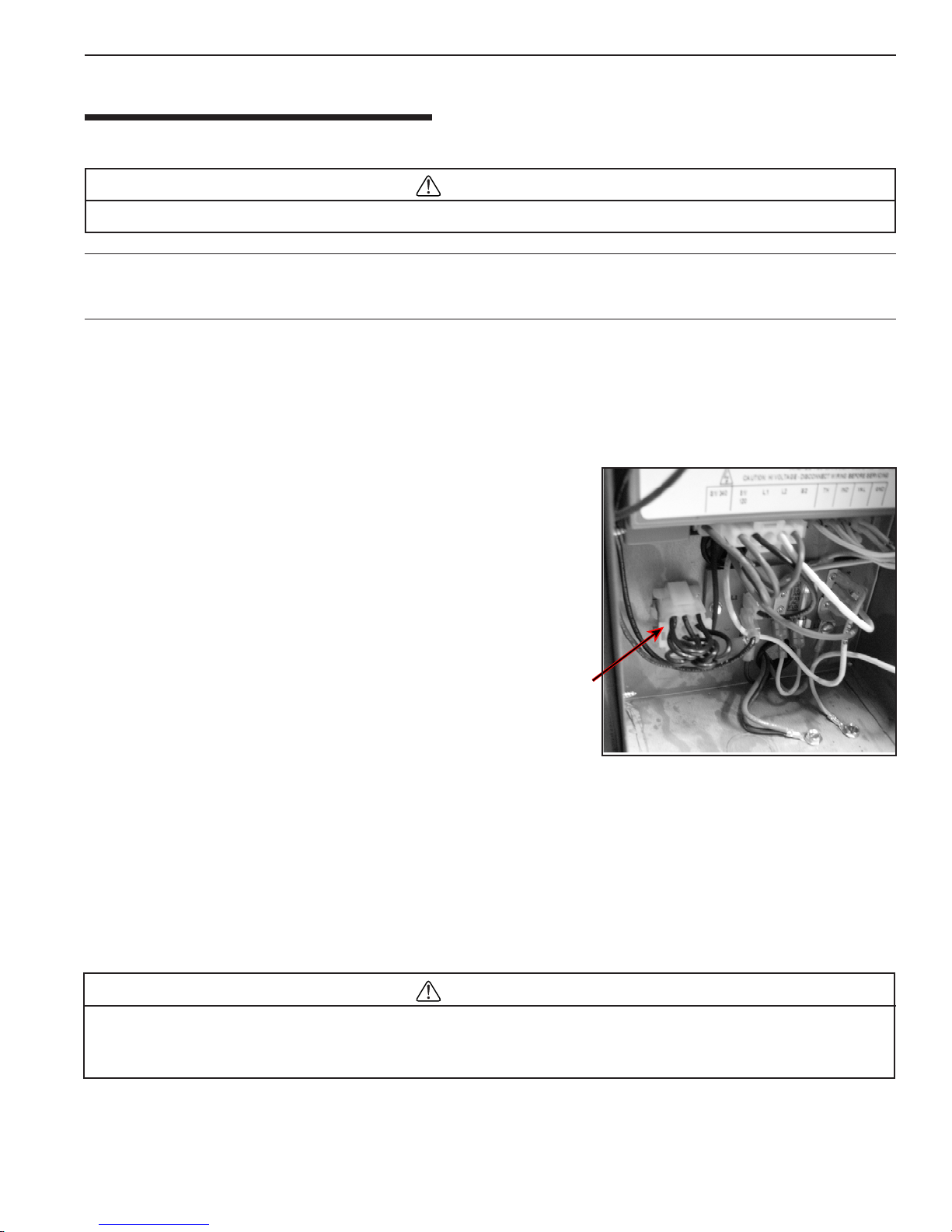
2. Installation
ELECTRICAL CONNECTIONS
Electrical Rating 50 Hz 240 Volts AC, single phase.
CAUTION
This heater is designed to operate at 240 V AC. It is not recommended to be connected to OR operate on a 208 V AC.
NOTE
If any of the original wiring supplied with this heater must be replaced, installer must supply (1.16 mm, 600V , 105° C, IEC approved
low energy stranded) copper wire or it’s equivalent.
Please read the boxes headed “IMPORTANT! READ ME FIRST!”
on pages 25 and 29 before proceeding.
1. All wiring must be in accordance with all applicable codes and
must be wired by a licensed electrician to the
European S tandard Codes of Practice wiring rules.
2. The heater, when installed, must be electrically grounded and
bonded in accordance with European Standard Codes of
Practice. A bonding lug is provided on the outside of the panel
under the vent for this purpose.
240 VA C Power Plug.
| 21
3. Electrical power circuits to the pool heater must follow European
Standard Codes of Practice.
4. All wiring between the heater and devices not attached to it, or
between separate devices which are installed in the field, must
be “Type T” wire rated for 35°C rise.
5. The filter pump should run continuously when the heater is
on, and for at least 15 minutes after the heater turns off.
Any switches in the pump circuit (including circuit breakers)
that can disconnect the pump must also disconnect the heater.
6. Do not wire single-pole switches, including protective devices,
into a grounded line. The heater is not sensitive to polarity .
Use the provided waterproof wire nuts when connecting the
power supply.
A time clock controlling the filter pump should have a low-voltage Fireman’ s Switch that switches off the heater at least 15
minutes before shutting off the pump.
AC Plug
240 Volt
Figure 27.
CONNECTION OF FIREMAN’S SWITCH OR REMOTE CONTR OL
CAUTION
If, while there is line voltage connected to the heater , you touch either line voltage terminal with any 24VAC wire that is
connected to the control board (including the Fireman’s Switch jumper), you will immediately destroy the control board
and void the warranty .
P/N 475106 Rev. D 1/2016 MASTERTEMP™ Pool and Spa Heater Installation and User’s Guide
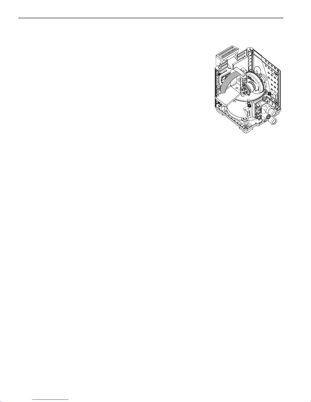
22 | Section
Section 2. Installation
REMOTE CONTR OL CONNECTIONS
1. Switch off power to heater at main circuit breaker panel.
2. Unbolt and remove the access door panels.
3. Open control box cover (see Figure 28).
4a. T o connect a 2-Wir e Control (such as Pentair’ s IntelliT ouch
Systems) or a timer:
- Remove the factory installed jumper from the Fireman’s Switch terminals.
- Connect wires between the Fireman’s Switch terminals on the heater and the
relay. Connect wires from the controller or timer to the Fireman’s Switch.
Controller, timer or relay should be sized to handle 24VAC at 0.5 Amp (because
it will be completing the 24VAC control board circuit on the heater as shown in
Figure 30). DO NOT apply line voltage to the Fireman’ s Switch terminals. Use
18 gauge (1.16 mm) wire with a minimum 1.2 mm (3/64 in.) thick insulation
rated for a temperature rise of at least 105° C.
- Knock-outs are provided to route the wires through the bottom of the control box
and past the junction box.
4b. To connect a 3-Wire Control:
- Connect wires between the control board terminals on the heater and the external relays, as shown in Figure 30 on
page 26. Use at least 2 relays per heater, to allow for an “OFF setting” on each heater mode. Select relays that can
handle logic level switching. DO NOT apply line voltage to control board terminals.
- Move jumper (as shown in Figure 30 on page 23) to enable external control and to disable the heater membrane pad’s
“Pool ON” and “Spa ON” buttons (the “OFF” key on the membrane pad remains functional).
- Knock-outs are provided to route the wires through the bottom and the top of the control box and past the junction
box.
5. Close control box cover.
6. Re-install the access door panels.
T o control heaters that are operated in parallel, connect wiring at same locations on heater as 2-Wire or 3-W ire Control. It
is imperative that each control circuit is isolated from the other control circuits, to avoid that current will flow from one
heater to another through the control circuits.
™
or EasyT ouch™ Control
Figure 28.
NOTICE: The fuse for the Fireman’s Switch is a 1.25 Amp 31.75 mm x 6.35 mm fast blow fuse, which is commonly
available.
MASTERTEMP™ Pool and Spa Heater Installation and User’s Guide P/N 475106 Rev. D 1/2016
Figure 29.
 Loading...