

Pentair MasterTemp 175, MasterTemp 200, MasterTemp 300, MasterTemp 250, MasterTemp 400 Installation And User Manual
Page 1

1
MASTERTEMP POOL AND SPA HEATER
®
INSTALLATION AND USER’S GUIDE
FOR YOUR SAFETY - READ BEFORE OPERATINGFOR YOUR SAFETY - READ BEFORE OPERATING
FOR YOUR SAFETY - READ BEFORE OPERATING
FOR YOUR SAFETY - READ BEFORE OPERATINGFOR YOUR SAFETY - READ BEFORE OPERATING
If you do not follow these instructions exactly, a fire or explosion may result, causing
property damage, personal injury or loss of life. For additional free copies of this manual;
call (800) 831-7133.
FOR YOUR SAFETYFOR YOUR SAFETY
FOR YOUR SAFETY - This product must be installed and serviced by authorized personnel, qualified inpool/spa
FOR YOUR SAFETYFOR YOUR SAFETY
heater installation. Improper installation and/or operation can create carbon monoxide gas and flue gases which can
cause serious injury, property damage, or death. For indoor installations, as an additional measure of safety, Pentair
Water Pool and Spa strongly recommends installation of suitable
appliance and in any adjacent occupied spaces. Improper installation and/or operation will void the warranty.
120/240 VAC NATURAL GAS/LP GAS120/240 VAC NATURAL GAS/LP GAS
120/240 VAC NATURAL GAS/LP GAS
120/240 VAC NATURAL GAS/LP GAS120/240 VAC NATURAL GAS/LP GAS
Models Natural Propane
175K BTU/HR 460792 460793
200K BTU/HR
200K BTU/HR 460730 460731
200K BTU/HR
250K BTU/HR 460732 460733
250K BTU/HR (HD) 460806 –
250K BTU/HR
250K BTU/HR
300K BTU/HR 460734 460735
400K BTU/HR 460736 460737
400K BTU/HR (HD) 460805 –
400K BTU/HR
400K BTU/HR
(ASME)
(HD ASME)
(ASME)
(HD ASME)
(ASME)
(HD ASME)
461000 461001
461032 –
460771 460772
461020 –
460775 460776
461021 –
Carbon Monoxide detectorsCarbon Monoxide detectors
Carbon Monoxide detectors in the vicinity of this
Carbon Monoxide detectorsCarbon Monoxide detectors
OWNER:OWNER:
OWNER:
OWNER:OWNER:
Retain ForRetain For
Retain For
Retain ForRetain For
FutureFuture
Future
FutureFuture
ReferenceReference
Reference
ReferenceReference
Improper installation, adjustment, alteration, service or maintenance can cause
propertydamage, personal injury or death. Installation and service must be performed by
a qualified installer, service agency or the gas supplier.
WHAT TO DO IF YOU SMELL GASWHAT TO DO IF YOU SMELL GAS
WHAT TO DO IF YOU SMELL GAS
WHAT TO DO IF YOU SMELL GASWHAT TO DO IF YOU SMELL GAS
• Do not try to light any appliance.
FORFOR
FOR
FORFOR
YOURYOUR
YOUR
YOURYOUR
SAFETYSAFETY
SAFETY
SAFETYSAFETY
Rev. N 10/2018 MASTERTEMP Pool and Spa Heater Installation and User’s Guide
• Do not touch any electrical switch; do not use any phone in your building.
• Immediately call your gas supplier from a neighbor's phone.
Follow the gas supplier's instructions.
• If you cannot reach your gas supplier, call the fire department.
DO NOT store or use gasoline or other flammable vapors and liquids in the vicinity
of this or other appliances.
1620 Hawkins Ave., Sanford, NC 27330 • (800) 831-7133 or (919) 566-8000
10951 W. Los Angeles Ave., Moorpark, CA 93021
Pentair Water Pool and Spa, Inc.
• (800) 831-7133 or (805) 553-5000
Page 2

2
Customer Service
8:00 AM to 8:00 PM
Phone: (800) 831-7133
Fax: (800) 284-4151
Visit www.pentair .com
Te chnical Support
Sanford, North Carolina (8:00 AM to 8:00 PM ET)
Phone: (919) 566-8000
Fax: (919) 566-8920
Moorpark, California (8:00 AM to 5:00 PM PT)
Phone: (805) 553-5000
Fax: (805) 553-5515
P/N 472592 Rev . N 10/2018
MASTERTEMP Pool and Spa Heater Installation and User’s Guide Rev. N 10/2018
Page 3

Contents
Section 1. Heater Identification Information ....................................................................... 4
Section 2. Warning and Safety Information ......................................................................... 5
Important Notices................................................................................................................................................................................. 5
Warranty Information ............................................................................................................................................................................ 5
Code Requirements .............................................................................................................................................................................. 6
Consumer Information and Safety Information ...................................................................................................................................... 6 - 9
General Specifications ......................................................................................................................................................................... 9
Section 3. Installation ............................................................................................................. 10
Heater Description................................................................................................................................................................................ 10
Putting the Heater into Service ............................................................................................................................................................ 10
Specifications ...................................................................................................................................................................................... 11
Plumbing Connections.......................................................................................................................................................................... 12
Valves.................................................................................................................................................................................................. 12
Manual By-Pass .................................................................................................................................................................................. 12
Water Connections ............................................................................................................................................................................... 13
Below Pool Level Installation ................................................................................................................................................................ 13
Gas Connections ................................................................................................................................................................................. 14
Sediment Traps.................................................................................................................................................................................... 14
Gas Pipe Sizing ................................................................................................................................................................................... 15
Testing Gas Pressure / Gas Pressure Requirements .......................................................................................................................... 15-16
Outdoor Installation / Heater Clearances ............................................................................................................................................ 16
Outdoor Installation Venting Guidelines ........................................................................................ ..................................................... 17
Indoor Venting — General Requirements (Category I and Category III requirements)...................................................................... 18
Heater Clearances — General Requirements (Indoor Installation US / Canada) .............................................................................. 18
Outside Vent Cover Removal.............................................................................................................................................................. 18
Combustion Air Supply / Direct Air Intake Duct with 3-inch PVC Pipe (Indoor Installation) .................................................................. 19-20
Corrosive Vapors and Possible Causes .............................................................................................................................................. 20
Vent Installation (Indoor Installation for US and Canada).................................................................................................................... 21
Vertical Venting - Negative Pressure .................................................................................................................................................. 21 - 23
Horizontal or Vertical Venting - Positive Pressure .............................................................................................................................. 24
Connecting Special Gas Venting ........................................................................................................................................................ 24 - 26
Garage or Utility Room Installation ..................................................................................................................................................... 27
Control Panel Indexing ....................................................................................................................................................................... 28
Final Installation Check....................................................................................................................................................................... 28
Electrical Connections ........................................................................................................................................................................ 29
Fireman’s Switch Connection / Remote Control Connections ............................................................................................................ 30
MasterTemp Heater Wiring Diagram ................................................................................................................................................... 31
Electrical Schematic Ladder Diagram ................................................................................................................................................. 32
Section 4. Operation ............................................................................................................... 33
Basic System Operation ...................................................................................................................................................................... 33
HSI (Hot-Surface Ignition) Lighting / Operation ................................................................................................................................... 33
Operating ............................................................................................................................................................................................ 34
To Turn Off Gas to Appliance .............................................................................................................................................................. 34
Safety Controls.................................................................................................................................................................................... 35 - 37
Section 5. Troubleshooting .................................................................................................... 38
Initial Troubleshooting and Troubleshooting Chart ................................................................................................................................. 38
Heater Will Not Fire Troubleshooting .................................................................................................................................................... 39 - 42
LED Diagnostics .................................................................................................................................................................................. 43 - 44
Burner / Heat Exchanger Troubleshooting ............................................................................................................................................ 45
Section 6. Maintenance ..........................................................................................................46
Care and Maintenance.......................................................................................................................................................................... 46
Pressure Relief V alve........................................................................................................................................................................... 46
After Start-Up ...................................................................................................................................................................................... 47
Spring, Fall and Winter Operation ......................................................................................................................................................... 47
Maintaining Pool T emperature............................................................................................................................................................... 48
Energy Saving Tips.............................................................................................................................................................................. 49
Chemical Balance ................................................................................................................................................................................ 48 - 49
Replacement Parts.............................................................................................................................................................................. 50 - 54
Addendum: For Gas Pipe Escutcheon Installation.............................................................. 55
3
Rev. N 10/2018 MASTERTEMP Pool and Spa Heater Installation and User’s Guide
Page 4

4
Section 1. Heater Identification Information
Section 1: Heater Identification Information
To identify the heater, see rating plate on the inner front panel of the heater. There are two designators for each
heater, one is the
a. Heater Identification Number (HIN)
The following example simplifies the identification system:
1) MT : MasterTemp
2) Model Size : (175, 200, 250, 300 or 400) : Input rating (Btu/hr) X 1000
3) Fuel Type : (LP = Propane gas or NA = Natural gas)
4) Construction :(STD = Standard Model)
HEATER IDENTIFICATION INFORMATION — (HIN)
Model Number and the other is the Heater Identification Number (HIN).
(HD = Heavy Duty Model)
(ASME = ASME Certified Model)
(HD ASME = Heavy Duty ASME Model)
H. I. N.
HEATER IDENTIFICATION NUMBER
ID DESIGNATOR FOR PENTAIR AQUATIC SYSTEMS MASTERTEMP HEATERS
Example:
1 2 3 4
MT 250 NA ASME
STD = STANDARD MODEL
CONSTRUCTION =
FUEL TYPE =
MODEL SIZE = BTU INPUT in 1000 of BTU / HR
HD = HEAVY DUTY MODEL
ASME = ASME CERTIFIED MODEL
HD ASME = HEAVY DUTY ASME MODEL
NA = NATURAL GAS
LP = PROPANE GAS
®
MASTERTEMP Pool and Spa Heater Installation and User’s Guide Rev. N 10/2018
MT = MASTERTEMP
Page 5

Section 2. Warning and Safety Instructions
Section 2: Warning and Safety Instructions
IMPORTANT SAFETY INSTRUCTIONS
READ AND FOLLOW ALL INSTRUCTIONS
SAVE THESE INSTRUCTIONS
5
MASTERTEMP
®
Pool and Spa Heater
Congratulations on your purchase of the MasterT emp Pool and Spa Heater. Proper installation and service of your new
heating system and correct chemical maintenance of the water will ensure years of enjoyment. The MasterTemp heater
is a compact, lightweight, efficient, induced-draft, gas fired high performance pool and spa heater that can be directly
connected to schedule 40 PVC pipe. The MasterTemp heater also comes equipped with the Pentair multifunction
temperature controller which shows, at a glance, the proper functioning of the heater. All MasterTemp heaters are
designed with a direct ignition device, HSI (hot-surface ignition), which eliminates the need for a standing pilot. The
MasterTemp heater requires an external power source (120/240 VAC 60 Hz) to operate.
SPECIAL INSTRUCTIONS TO OWNER: Retain this manual for future reference. This instruction manual provides
operating instructions, installation and service information for the MasterT emp high performance heater. The information
in this manual applies to all MasterTemp heater models. READ AND REVIEW THIS MANUAL COMPLETEL Y,
it is very important that the owner/installer read and understand the section covering installation instructions, and recognize
the local and state codes before installing the MasterTemp heater. Its use will reduce service calls and chance of injury
and will lengthen product life. History and experience has shown that most heater damage is caused by improper installation
practices.
IMPORT ANT NO TICES
For the installer and operator of the MasterTemp heater: The manufacturer’s warranty may be void if, for any
reason, the heater is improperly installed and/or operated. Be sure to follow the instructions set forth in this manual. If you
need any more information, or if you have any questions regarding to this pool heater, please contact Pentair Water Pool
and Spa at (800) 831-7133.
WARRANTY INFORMATION
The MasterTemp pool and spa heater is sold with a limited factory warranty. Specific details are described on the
warranty registration card which is included with the product. Return the warranty registration card after filling in
the serial number from the rating plate inside the heater.
Pentair Water Pool and Spa high standards of excellence include a policy of continuous pr oduct improvement resulting
in your state-of-the-art heater. We r eserve the right to make improvements which change the specifications of the heater
without incurring an obligation to update the current heater equipment.
These heaters are designed for the heating of chlorine, bromine or salt system swimming pools and spas or
in non-stationary installations, and should never be employed for use as space heating boilers or general
purpose water heaters. The manufacturer’s warranty may be void if, for any reason, the heater is improperly
installed and/or operated. Be sure to follow the instructions set forth in this manual.
CAUTION
OPERATING THIS HEATER CONTINUOUSLY AT WATER TEMPERATURE BELOW 68° F. WILL CAUSE HARMFUL
CONDENSATION AND WILL DAMAGE THE HEATER AND VOID THE WARRANTY. Do not use the heater to protect
pools or spas from freezing if the final maintenance temperature desired is below 68° F., as this will cause condensation
related problems.
Rev. N 10/2018 MASTERTEMP Pool and Spa Heater Installation and User’s Guide
Page 6

6
Section 2. W arning and Safety Instructions
CODE REQUIREMENTS
Installation must be in accordance with all local codes and/or the latest edition of the National Fuel Gas Code,
ANSI Z223.1 and the latest edition of the National Electrical Code, NFPA 70 (US).
Installation in Canada must be in accordance with the latest CAN/CGA-B149.1 or .2 and CSA C22.1 Canadian
Electric Code, part 1.
The heater, when installed, must be electrically grounded and bonded in accordance with local codes, or , in absence of
local codes, with the National Electrical Code, ANSI/NFPA70 (US) or in Canada in accordance with the Canadian
Electric Code, part 1.as applicable.
D ANGER
CARBON MONOXIDE GAS IS DEADLY – Exhaust from this pool heater contains toxic levels of carbon monoxide, a dangerous,
poisonous gas you cannot see or smell.
CONSUMER INFORMA TION AND SAFETY
WARNING
The U.S. Consumer Product Safety Commission warns that elevated water temperature can be hazardous.
See below for water temperature guidelines before setting temperature.
1 . Spa or hot tub water temperatures should never exceed 104° F (40° C). A temperature of 100° F (38° C) is considered safe for a
healthy adult. Special caution is suggested for young children.
2 . Drinking of alcoholic beverages before or during spa or hot tub use can cause drowsiness which could lead to unconsciousness
and subsequently result in drowning.
3 . Pregnant women beware! Soaking in water above 102° F (39° C) can cause fetal damage during the first three months of pregnancy
(resulting in the birth of a brain-damaged or deformed child). Pregnant women should stick to the 100° F (38° C) maximum rule.
4. Before entering the spa or hot tub, the user should check the water temperature with an accurate thermometer. Spa or hot tub
thermostats may err in regulating water temperatures by as much as 4° F (2.2° C).
5. Persons with a medical history of heart disease, circulatory problems, diabetes or blood pressure problems should obtain their
physician's advice before using spas or hot tubs.
6 . Persons taking medication which induce drowsiness, such as tranquilizers, antihistamines or anticoagulants should not use spas
or hot tubs.
Should overheating occur or the gas supply fail to shut off, turn off the manual gas control valve to the heater .
Do not use this heater if any part has been under water. Immediately call a qualified service technician to
inspect the heater and to replace any part of control system and gas control which has been under water .
MASTERTEMP Pool and Spa Heater Installation and User’s Guide Rev. N 10/2018
WARNING
Page 7

Section 2. Warning and Safety Instructions
7
SAFETY INFORMA TION
The MasterTemp® pool heaters are designed and manufactured to provide many years of safe and reliable service when
installed, operated and maintained according to the information in this manual. Throughout the manual, safety warnings and
cautions are identified by the “ “ symbol. Be sure to read and comply with all of the warnings and cautions.
DANGER —
CARBON MONOXIDE GAS IS DEADLY
READ OWNERS MANUAL COMPLETELY BEFORE OPERATING
THIS PRODUCT MUST BE INSTALLED AND SERVICED BY A PROFESSIONAL SERVICE
TECHNICIAN, QUALIFIED IN POOL HEATER INSTALLATION. Some jurisdictions require that
installers be licensed. Check with your local building authority about contractor licensing requirements.
Improper installation and/or operation could create carbon monoxide gas and flue gases which could cause
serious injury or death. Improper installation and/or operation will void the warranty.
Exhaust from this pool heater contains toxic levels of carbon monoxide, a dangerous, poisonous gas
you cannot see or smell. Symptoms of carbon monoxide exposure or poisoning include dizziness,
headache, nausea, weakness, sleepiness, muscular twitching, vomiting and inability to think clearly.
IF YOU EXPERIENCE ANY OF THE ABOVE SYMPTOMS, IMMEDIATELY TURN OFF THE POOL
HEATER, LEAVE THE VICINITY OF THE POOL OR SPA AND GET INTO FRESH AIR IMMEDIATELY.
THE POOL HEATER MUST BE THOROUGHLY TESTED BY A GAS PROFESSIONAL BEFORE
RESUMING OPERATION.
EXCESSIVE CARBON MONOXIDE EXPOSURE CAN CAUSE BRAIN DAMAGE OR DEATH.
NEVER use this pool heater indoors without specified ventilation system (and properly installed vent pipe).
NEVER use this pool heater in the home or in partly enclosed areas (such as garages), unless
the specified ventilation system is used. If used outdoors, install far from open windows, doors,
vents and other openings.
Pentair strongly recommends that all vents, pipes and exhaust systems be initially and periodically
tested for proper operation. This testing can be accomplished by using a hand-held carbon monoxide
meter and/or by consulting with a gas professional.
Pool heaters must be used in conjunction with carbon monoxide detectors installed near the pool heater.
The carbon monoxide detectors must be periodically inspected for proper operation so as to insure
continued safety. Broken or malfunctioning carbon monoxide detectors must be replaced immediately.
WARNING — FOR YOUR SAFETY
This product must be installed and serviced by a professional service technician, qualified in pool
heater installation. Some jurisdictions require that installers be licensed. Check with your local
building authority about contractor licensing requirements. Improper installation and/or operation
could create carbon monoxide gas and flue gases which could cause serious injury or death. Improper
installation and/or operation will void the warranty.
WARNING —
This heater is equipped with an unconventional gas control valve that is factory set with a
manifold pressure of -.2 inches wc. Improper installation, adjustment, alteration, service or
maintenance can cause property damage, personal injury or loss of life. Installation or service must
be performed by a qualified installer, service agency or the gas supplier. If this control is replaced, it
must be replaced with an identical control.
Do not attempt to adjust the gas flow by adjusting the regulator setting.
Rev. N 10/2018 MASTERTEMP Pool and Spa Heater Installation and User’s Guide
Page 8

8
SAFETY INFORMA TION, (cont’d.)
WARNING —
WARNING —
Risk of fire or explosion from incorrect fuel use or faulty fuel conversion. Do not try to run a
heater set up for natural gas on propane gas or vice versa. Only qualified service technicians should
attempt to convert heater from one fuel to the other. Do not attempt to alter the rated input or type of
gas by changing the orifice. If it is necessary to convert to a different type of gas, consult your Pentair
dealer. Serious malfunction of the burner can occur which may result in loss of life. Any additions,
changes, or conversions required in order for the appliance to satisfactorily meet the application
needs must be made by a Pentair dealer or other qualified agency using factory specified and
approved parts. The heater is available for use with natural gas or LP (propane) gas only. It is not
designed to operate with any other fuels. Refer to the nameplate for the type of gas the heater is
equipped to use.
• Use heater only with the fuel for which it is designed.
• If a fuel conversion is necessary, refer this work to a qualified service technician or gas supplier
before putting the heater into operation.
Risk of fire or explosion from flammable vapors. Do not store gasoline, cleaning fluids, varnishes,
paints, or other volatile flammable liquids near heater or in the same room with heater.
Section 2. Warning and Safety Instructions
WARNING —
WARNING —
WARNING —
CA UTION —
Risk of explosion if unit is installed near propane gas storage. Propane (LP) gas is heavier
than air. Consult local codes and fire protection authorities about specific installation requirements
and restrictions. Locate the heater away from propane gas storage and filling equipment as specified
by the Standard for the Storage and Handling of Liquefied Petroleum Gases, CAN/CSA B149.2
(latest edition) or ANSI/NFPA 58 (latest edition).
Risk of fire, carbon monoxide poisoning, or asphyxiation if exhaust venting system leaks.
Only qualified service technicians should attempt to service the heater, as leakage of exhaust
products or flammable gas may result from incorrect servicing.
Risk of asphyxiation if exhaust is not correctly vented. Follow venting instructions exactly
when installing heater. Do not use a drafthood with this heater, as the exhaust is under
pressure from the burner blower and a draft hood will allow exhaust fumes to blow into the room
housing the heater. The heater is supplied with an integral venting system for outdoor installation.
A vent conversion kit (See Page 24 for Part Numbers for Conversion Kits) is available for installations
indoors (US and Canada). Use the specified venting, and only the specified venting, when heater is
installed in an enclosure or indoors.
Label all wires prior to disconnection when servicing controls. Wiring errors can cause improper
and dangerous operation. Wiring errors can also destroy the control board.
• Connect heater to 120 or 240 Volt, 60 Hz., Single Phase power only.
• Verify proper operation after servicing.
• Do not allow children to play on or around heater or associated equipment.
• Never allow children to use the pool or spa without adult supervision.
• Read and follow other safety information contained in this manual prior to operating this pool
heater.
MASTERTEMP Pool and Spa Heater Installation and User’s Guide Rev. N 10/2018
Page 9

Section 2. Warning and Safety Instructions
9
CONSUMER INFORMA TION AND SAFETY
WARNING
The U.S. Consumer Product Safety Commission warns that carbon monoxide is an "invisible killer". Carbon monoxide
is a colorless and odorless gas.
1. Carbon monoxide is produced by burning fuel, including natural gas and propane.
2. Proper installation, operation and maintenance of fuel-burning appliances in the home is the most important
factor in reducing carbon monoxide poisoning.
3. Be sure that fuel burning appliances such as heaters are installed by professionals according to manufacturer's
instructions and codes.
4. Always follow the manufacturer's directions for safe operation.
5. Have the heating system (including vents) inspected and serviced annually by a trained service technician.
6. Examine vents regularly for improper connections, visible cracks, rust or stains.
7. Install battery-operated carbon monoxide alarms. The alarms should be certified to the requirements of the
most recent UL, IAS, CSA and IAPMO standard for carbon monoxide alarms. Test carbon monoxide alarms
regularly and replace dead batteries.
GENERAL SPECIFICA TIONS
NOTICE:
• Combustion air contaminated by corrosive chemical fumes can damage the heater and will void the warranty.
• The Combination Gas Control Valve on this heater differs from most appliance gas controls. If it must be replaced,
for safety reasons replace it only with an identical gas control.
• The access door panels must be in place to provide proper ventilation. Do not operate the heater for more than
five (5) minutes with the access door panels removed.
• This heater is design certified by CSA International as complying with the Standard for Gas Fired Pool Heaters,
ANSI Z21.56/CSA 4.7, and is intended for use in heating fresh water swimming pools or spas.
• The heater is designed for the heating of chlorine, bromine or salt system swimming pools and spas. It should
NOT beused as a space heating boiler, or general purpose water heater.
• The heater is design certified by CSA International for installation on combustible flooring. Specified minimum
clearances must be maintained to combustible surfaces (see “Heater Clearances”, page 18).
• The heater should be located in an area where leakage of the heater or connections will not result in damage
to the area adjacent to the heater or to the structure. When such locations cannot be avoided, it is recommended
that a suitable drain pan, adequately drained, be installed under the heater. The pan must not restrict air flow.
• The heater may not be installed within 5 ft. (1.5M ) of the inside surface of a pool or spa unless it is separated
by a solid fence, wall or other permanent barrier.
Rev. N 10/2018 MASTERTEMP Pool and Spa Heater Installation and User’s Guide
Page 10

10
Section 3: Installation Instructions
HEA TER DESCRIPTION
Section 3. Installation Instructions
Figure 1 is a diagram of the heater showing how it operates. Precisely
Gas
matched orifice plates meter the air and gas into the mixer. The
blower draws the air and gas through the mixer and forces it into
the burner’s flame holder. A sealed heat exchanger surrounds the
flame holder, discharging exhaust gases out the flue.
T wo inch PVC water piping connects directly to the manifold/header
on the heat exchanger using 2" PVC slip unions provided with the
heater. The outer manifold remains cool; no heat sinks are required.
Inlet
(Cold
Water)
Air
Mixer
Blower
Exhaust
A thermal regulator and an internal bypass regulate the water flow
through the heat exchanger to maintain the correct outlet
temperature. The heater operator control panel board assembly is
located on top of the heater.
SEQUENCE OF OPERA TION
Outlet
(Mixed
Water)
Burner
Heating Coils
An electronic temperature sensing thermistor in the manifold
adapter inlet controls the heater operation. When the inlet water
Figure 1.
temperature drops below the temperature set on the operating
control, the burner controller supplies power to the combustion
air blower through a series of safety interlocks. The interlocks consist of:
• the pressure switch (PS), which senses that the pump is running,
• the high limit switch (HLS), which opens if the heat exchanger outlet temperature goes above 135° F (57° C), and
• the air flow switch (AFS), which senses the pressure drop across the air metering orifice,
• the automatic gas shut-off (AGS) switch, which opens if the heat exchanger outlet temperature goes above 140° F
(60° C).
• the stack flue sensor (SFS), which shuts down the heater if the flue gas temperature reaches 480° F (249° C).
The air flow switch (AFS) senses the pressure drop across the air metering orifice. As soon as there is suf ficient air flow,
the AFS closes, closing the circuit to the hot surface igniter (HSI), which ignites the fuel mixture. On a call for heat, the
blower and HSI are energized. In about 20 seconds, the gas valve opens and ignition occurs. The HSI then switches to a
sensing mode and monitors the flame.
The heater is equipped with a digital operating control that enables the user to pre-set the desired pool and spa water
temperatures. The control enables the user to select between pool and spa heating, and features a digital display that
indicates the water temperature.
PUTTING THE HEATER INTO SERVICE
If the heater is installed below the level of the pool, or more than two feet above pool level, the pressure switch setting
should be adjusted. See WATER PRESSURE SWITCH, in the SAFETY CONTROLS Section.
Before putting the heater into service for the first time, follow the instructions under “BEFORE ST AR T -UP” (page 33) in
the front of this manual. Check for proper operation of the heater by following the steps under “OPERATION
INSTRUCTIONS.”
Damage to equipment caused by improper installation or repair will void the warranty.
MASTERTEMP Pool and Spa Heater Installation and User’s Guide Rev. N 10/2018
Page 11
Section 3. Installation Instructions
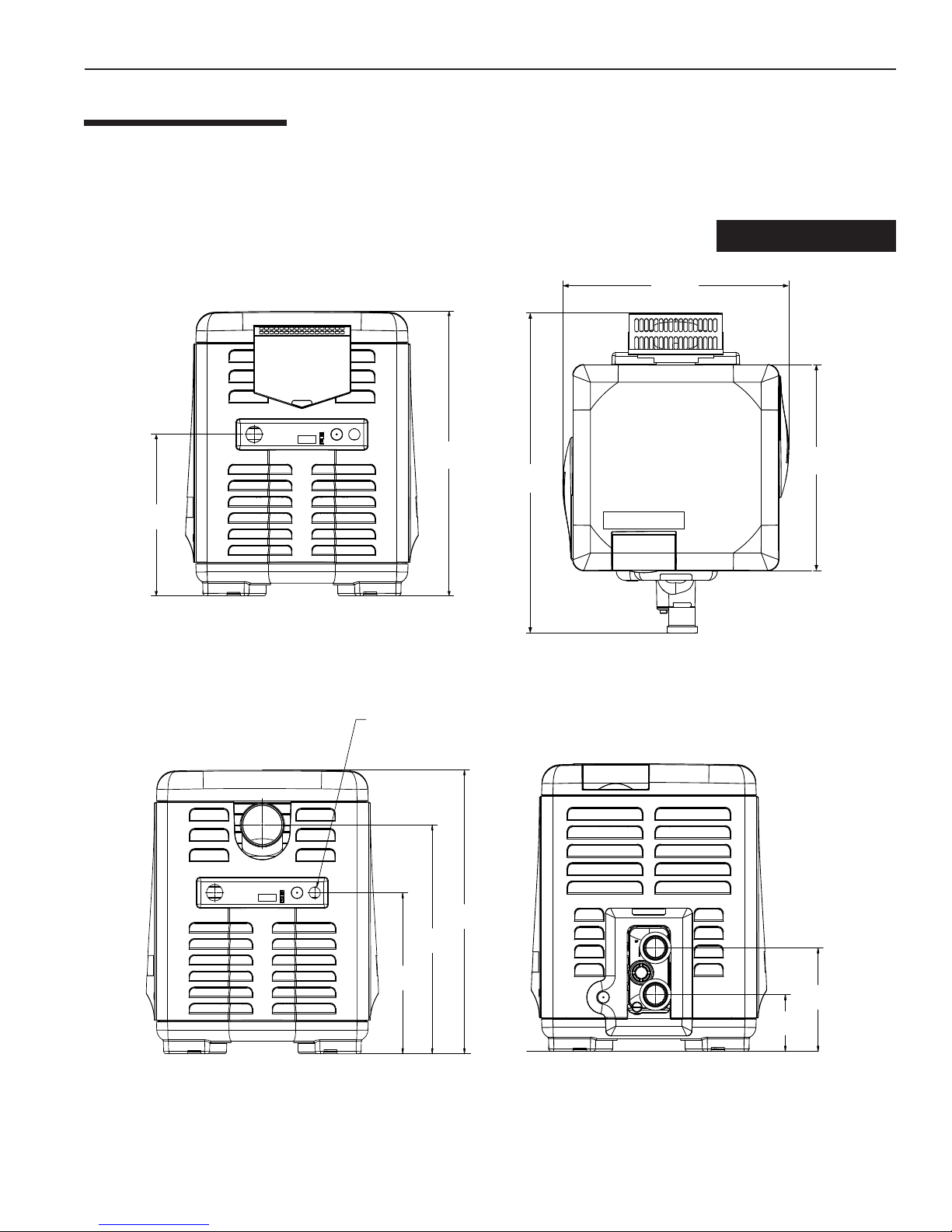
SPECIFICATIONS
These installation instructions are designed for use by qualified personnel only, trained especially for installation of this
type of heating equipment and related components. Some states require installation and repair by licensed personnel. If
this applies in your state, be sure your contractor bears the appropriate license. See Figure 2 for Outdoor and Indoor
Installations.
DIMENSIONS IN INCHES
23.02"
(58.5 cm)
11
16"
(40.6 cm)
28.15"
(71.5 cm)
ELECTRICAL
CONDUIT PORT
32.61"
(82.8 cm)
21.0"
(53.3 cm)
TOPFRONT
EXHAUST SIDE
Rev. N 10/2018 MASTERTEMP Pool and Spa Heater Installation and User’s Guide
16.0"
(40.6 cm)
22.7"
(57.7 cm)
28.2"
(71.6 cm)
Figure 2.
PLUMBING SIDE
5.6"
(14.2 cm)
10.13"
(25.7 cm)
Page 12

12
PLUMBING CONNECTIONS
The MasterTemp heater has the unique capability of direct
schedule 40 PVC plumbing connections. A set of bulkhead
fittings is included with the MasterTemp heater to insure
conformity with Pentair’s recommended PVC plumbing
procedure. Other plumbing connections can be used. See
Figure 3 for plumbing connections.
Section 3. Installation Instructions
CAUTION
POOL
HEATER
Before operating the heater on a new installation, turn
on the circulation pump and bleed all the air from the
MANUAL
BY-PASS
TO
POOL
GATE
VALVE
FILTER
PUMP
filter using the air relief valve on top of the filter. Water
should flow freely through the heater. Do not operate
the heater unless water in the pool/spa is at the proper
Figure 3.
FROM
POOL
level. If a manual by-pass is installed, temporarily close it
to insure that all air is purged from the heater.
W A TER CONNECTIONS
The heater requires proper water flow and pressure for its
operation. See Figure 5 for the recommended installation.
The filter pump discharges to the filter , the filter discharges
to the heater, and the heater discharges directly to the pool
or spa.
A manual bypass valve should be installed across the heater
when the pump flow exceeds 120 GPM (454 LPM). See
“WA TER FLOW RATE” on page 13- Table 1 for setting of
the manual by-pass valve.
Make sure that the outlet plumbing from the heater contains
Main
Drain
Pool
no shut-off valves or other flow restrictions that could prevent
flow through the heater (except for pool installations as noted
below, or winterizing valves where needed). T
o switch flow
between the pool and spa, use a diverter valve. Do not use
any valve that can shut off the flow.
Install the chemical feeder downstream of the heater. Install
a chemical resistant one-way check valve between the heater
From Pool
3-Way
Valve
and the chemical feeder to prevent back-siphoning through
the heater when the pump is off.
NOTICE: If the heater is plumbed in backwards, it will cycle continuously. Make sure piping from filter is not reversed
when installing heater.
Connect the heater directly to 2" PVC pipe, using the integral unions provided. Heat sinks are not required. The low
thermal mass of the heater will prevent overheating of the piping connected to the pump even if the heater shuts down
unexpectedly .
Occasionally a two-speed pump will not develop enough pressure on the low speed to operate the heater. In this case, run
the pump at high speed only to operate the heater. If this does not solve the problem, do not try to run the heater. Instead,
correct the installation.
Do not operate the heater while an automatic pool cleaner is also operating. If the circulation pump suction is plugged (for
example by leaves), there may not be adequate flow to the heater. Do not rely on the pressure switch in this case.
3-Way
Valve
Heater
Spa
Figure 5.
Chlorinator
Check Valve
Filter
Pump
3-Way
Valve
MASTERTEMP Pool and Spa Heater Installation and User’s Guide Rev. N 10/2018
Page 13

Section 3. Installation Instructions
13
VALVES
When any equipment is located below the surface of the pool or spa, valves should be placed in the circulation piping
system to isolate the equipment from the pool or spa. Check valves are recommended to prevent back-siphoning. Backsiphoning is most likely to occur when the pump stops, creating a pressure-suction differential. Do NOT sanitize the pool
by putting chlorine tablets or sticks into the skimmer(s). When the pump is off, this will cause a high concentration of
chlorine to enter the heater, which could cause corrosion damage to the heat exchanger.
CAUTION
Exercise care when installing chemical feeders so as to not allow back siphoning of chemical into the heater, filters
or pump. When chemical feeders are installed in the circulation of the piping system, make sure the feeder outlet line
is down stream of the heater, and is equipped with a positive seal noncorrosive “Check Valve”, (P/N R172288),
between the feeder and heater.
MANU AL BY-PASS
Where the water flow rate exceeds the maximum 120 GPM, a manual
Figure 4.
bypass should be installed and adjusted. After installing the valve, adjust
the valve to bring the flow rate within the acceptable range. Then remove
the valve handle or lock it in place to avoid tampering. See Figure 4.
wolfdednemmocermumixamehtdeecxetonoD*
Table 1.
Cool water
Warm water out
1. Set Manual By-Pass Valve.
2. Remove Handle.
Outlet to pool
Inlet to heater
ledoM)MPL()MPG(.niM*)MPL()MPG(.xaM
571)67(02)454(021
002)67(02)454(021
052)59(52)454(021
003)411(03)454(021
004)251(04)454(021
.gnipipgnitcennocehtrofetar
* Pumps 2 HP or larger can produce water pressure
flow in excess of 120 GPM. For these pumps, a
BY-PASS VALVE is recommended.
See page 46 for Pressure Relief Valve Installations.
BELO W POOL LEVEL INST ALLA TION
If the heater is below water level, the pressure switch must be adjusted. This adjustment must be done by a qualified
service technician. See following CAUTION before installation.
BELOW OR ABOVE POOL INSTALLATION
The water pressure switch is set in the factory at 3.00 PSI (± 0.75 PSI). This setting is for a heater installed at pool level.
If the heater is to be installed more than 1’ above or below, the water pressure switch must be adjusted by a qualified
service technician. See page 35, Figure 29.
If the heater is installed more than 5’ above the pool or more than 4’ below the pool level, you will be beyond the limits
of the pressure switch and a flow switch must be installed. Locate and install the flow switch externally on the outlet
piping from the heater, as close as possible to the heater. Connect the flow switch wires in place of the water
pressure switch wires.
Rev. N 10/2018 MASTERTEMP Pool and Spa Heater Installation and User’s Guide
CAUTION
FLOW SWITCH
Page 14

14
Section 3. Installation Instructions
GAS CONNECTIONS
NOTE: SEE P AGE 55 T O INSTALL THE GAS PIPE ESCUTCHEON.
GAS LINE INST ALLA TIONS
Before installing the gas line, be sure to check which gas the heater has been designed to burn. This is important because
different types of gas require different gas pipe sizes. The rating plate on the heater will indicate which gas the heater is
designed to burn. The Table 2, shown on page 15, show which size pipe is required for the distance from the gas meter to
the heater. The table is for natural gas at a specific gravity of .65 and propane at a specific gravity of 1.55.
When sizing gas lines, calculate three (3) additional feet of straight pipe for every elbow used. When installing the gas line,
avoid getting dirt, grease or other foreign material in the pipe as this may cause damage to the gas valve, which may result
in heater failure.
The gas meter should be checked to make sure that it will supply enough gas to the heater and any other appliances
that may be used on the same meter. The gas line from the meter will usually be of a larger size than the gas valve
supplied with the heater. Therefore a reduction of the connecting gas pipe will be necessary. Make this reduction
as close to the heater as possible.
The heater requires a gas supply of not less than 4" (10.2 cm) wc and not more than 14" (35.6 cm) wc. Gas supply
pressures outside of this range may result in improper burner operation. A minimum flowing or dynamic inlet pressure
(while the heater is running) of 4" (10.2cm) wc is required to maintain input rating with no more than a 2” pressure drop
between static and dynamic. The gas supply must be installed in accordance with the National Fuel Gas Code,
ANSIZ223.1, or standard CSA B149.1, Natural Gas and Propane Installation Codes, as applicable and all applicable
local codes. Install a manual shut-off valve and a sediment trap and union located outside the heater panels, see Figure 6.
Do not use a restrictive gas cock. The following minimum gas pipe sizes are recommended for natural gas supply piping,
see Table 2 on page 15. For low pressure LP gas, pipe size may be reduced by 1/4", with a minimum pipe size of 1/2".
Check for compliance with local codes.
THIS ENSURES THE HEATER IS RODENT RESISTANT.
The heater and any other gas appliances must be disconnected from the gas supply piping system during any pressure
testing on that system, (greater than ½ PSI). The heater and its gas connection must be leak tested before placing the
heater in operation. Do not use flame to test the gas line. Use soapy water or another nonflammable method.
NOTE
A manual main shut-off valv e must be installed externally to the heater.
WARNING
DO NOT INSTALL THE GAS LINE UNION INSIDE THE HEATER CABINET. THIS WILL VOID YOUR WARRANTY.
SEDIMENT TRAPS
Install a sediment trap and union located outside the
heater panels in accordance with National code
requirements. Do not use a restrictive gas cock. The
sediment trap shall be either a tee fitting with a capped
nipple in the bottom outlet which can be removed for
cleaning, as illustrated in Figure 6, or an other device
recognized as an effective sediment trap. All gas piping
should be tested after installation in accordance with
local codes.
18–24" of 3/4"
Gas line from
Valve
Union
Sediment
Trap
1" Dia. or larger
(See "Recommended
Pipe Sizes" Chart)
Bell
Reducer
Figure 6.
At least 9"
At least 3"
Manual
Shut-off
Valve
MASTERTEMP Pool and Spa Heater Installation and User’s Guide Rev. N 10/2018
Page 15

Section 3. Installation
15
GAS PIPE SIZING
ST AGE TWO “LOW PRESSURE” GAS PIPE SIZING
SNOITCENNOCENILSAGROFGNIZISEPIP
HTGNELEPIPTNELAVIUQEMUMIXAM
).tF(
tooFcibuCrep.U.T.B0001tasaGlarutaN
tooFcibuCrep.U.T.B0052tasaGenaporP
”2/1”4/3”1”4/1-1”2/1-1”2”2/1-2
TANORPTANORPTANORPTANORPTANORPTANORPTANORP
LEDOM
571-’02’03’08’521’052’054’006 -----002-’02’03’08’521’052’054’006 -----052-’01’02’05’07’051’052’005’006 -----
----
Table 2.
003--’01’03’05’001’002’053’004’006
004
--- ’01’02’06’001’051’002’054’004 ---
TESTING GAS PRESSURE
Before operating the heater, the heater and its gas connections must be leak tested. Do NOT use an open flame to test
for leaks. Test all gas connections for leaks with soapy water or another non-flammable method (see page 14).
The heater and its individual shut-off valve must be disconnected from the gas supply piping system during any pressure
testing of that system at test pressures in excess of 1/2 psig (3.5 kPa).
The heater must be isolated from the gas supply system by closing its individual manual shut-off valve during any pressure
testing of the gas supply at test pressures equal to or less than 1/2 psig (3.5 kPa).
CHECKING THE GAS PRESSURE THROUGH THE COMBINATION GAS CONTROL VALVE
WARNING
Risk of fire and explosion. Improper installation, incorrect adjustment, alteration, service, or maintenance of the Combination
Gas Control Valve can lead to fire or explosion, causing loss of life, personal injury, and/or property damage. If it is necessary
to adjust the gas valve, this must be done by only by a qualified service agency. These instructions are for the use of
qualified service technicians only!
This appliance is equipped
with an unconventional gas
control valve that is factory
set with a manifold
pressure of –.2" (–0.5cm)
wc. Installation or service
To Air Flow
Switch
Connection
for Service
To Air Flow
Switch
To Gas
Valv e V ent
To Gas
Valve Vent
must be performed by a
qualified installer, service
agency , or the gas supplier.
If this control valve is
replaced, it must be
replaced with an identical
control.
The combination gas
To Low Side of
Differential Pressure Gauge
Pressure Tap
valve incorporates dual shut-off valves and a negative-pressure regulator. For proper operation, the regulated pressure
at the outlet manifold of the valve must be –0.2" (–0.5cm) wc below the reference pressure at the blower mixer inlet,
and the gas valve ‘VENT’ tap must be connected to the end cap air orifice as shown in Figure 7.
Do not attempt to adjust the gas input by adjusting the regulator setting. The correct gas regulator setting is
required to maintain proper combustion and must NOT be altered.
Ven t
Connection
for Test
To High Side
of Differential
Pressure Gauge
Figure 7.
Pressure Tap
Inlet
Rev. N 10/2018 MASTERTEMP Pool and Spa Heater Installation and User’s Guide
Page 16

16
Section 3. Installation Instructions
CAUTION
The use of Flexible Connectors (FLEX) is NOT recommended unless they are properly sized according to the supplier
recommendations for the heater rating.
GAS PRESSURE REQUIREMENTS
larutaNenaporP
.C.WsehcnI
lliwffosiretaehelihwedamsgnidaerrostnemtsujdaynA
:ETON .gnitareposiretaehelihwnekatebtsumsgnidaerllA
Table 3.
erusserPsaGledoM
telnImumixaM
telnImuminiM
dlofinaM
TM4141
TM4 4
TM1.0±2.0-1.0±2.0-
.smelborpecnamrofrepnitluser
OUTDOOR INSTALLATION LOCATED OUTDOORS, USING THE
BUILT-IN STACKLESS VENTING SYSTEM.
WARNING
Risk of explosion if a unit burning propane gas is installed in a pit or other low spot. Propane is heavier than air . Do not install
the heater using propane in pits or other locations where gas might collect. Consult your local building code officials to determine
installation requirements and specific installation restrictions of the heater relative to propane storage tanks and filling equipment.
Installation must meet the requirements for the Standard for the Storage and Handling of Liquid Petroleum Gases, ANSI/NFPA 58
(latest edition) in the U.S., or CAN/CSA B149.2 (latest edition) in Canada. Consult local codes and fire protection authorities about
specific installation restrictions.
Locate the heater on a level surface in an open area that is protected from drainage or run-off. Install the heater in an area
where leaves or other debris will not collect on or around the heater.
T o avoid damage to the electronic components in the heater, take care to prevent prolonged exposure to driving sources
of water (such as lawn sprinklers, heavy roof runoff, hoses, etc.). Avoid operation in persistent, extreme, moist or salty
environments. In extreme weather, shut down the heater and disconnect the power to it until the weather has moderated.
In areas subject to hurricanes or very high winds, purchase the Bolt Down Bracket Kit, P/N 460738.
HEA TER CLEARANCES – OUTDOOR
• In an outdoor installation it is important to ensure water is diverted from overhanging
eves with a proper gutter/drainage system. The heater must be set on a level f oundation
for proper drainage.
• This unit shall not be operated outdoors at temperatures below -20o F.
If the heater is located under a roof overhang, there must be at least three (3) feet (1m) of
clearance between the bottom of the overhang and the top of the heater exhaust vent, see Figure
8. If the heater is under a roof overhang, the space around the heater must be open on three sides.
DO NOT , under any cir cumstances, install the heater under ANY deck.
MASTERTEMP Pool and Spa Heater Installation and User’s Guide Rev. N 10/2018
IMPORTANT!
For Heater mounting
bolts and clamps,
purchase separately
Bolt Down Bracket Kit,
Part No.
460738.
Lead
Anchor
Page 17

Section 3. Installation Instructions
17
For minimum exhaust vent clearances for all building openings, including but not limited to vented eaves, doors, windows,
gravity air inlet, see Figure 9, show below.
In Canada, the heater must be installed with the top of the vent at least 10 feet (3m) below, or to either side of, any opening
into a building.
Orient the heater for convenient access to the water connections and the gas and electrical connections.
Note: Check local building codes for installing the heater from any property line set back requirements (see the
installation diagram below).
CAUTION
If installing the heater next to or near an air
conditioning unit or a heat pump, allow a
minimum of 36 in. (91.4 cm) between the air
conditioning unit and the heater.
3 ft. (1 M) or more
Building
Figure 9.
6 in
Exhaust Grill
(Vent)
OUTDOOR INSTALLATION
VENTING GUIDELINES
SIDE VIEW
From building wall
Figure 8.
From window or door
3'
4'
4'
Force
Air Inlet
4'
Property Line
Check local building codes
for setback requirements.
Vent T ermination:
Must be at least 3 ft. above any forced
air inlet located within a 10 ft. radius.
Must be located 6 in. away from the building
wall and the following distances away from any building
wall openings, included but not limited to vented eaves,
doors, windows, gravity air inlet:
4 ft. below,
4 ft. horizontally
Rev. N 10/2018 MASTERTEMP Pool and Spa Heater Installation and User’s Guide
Page 18

18
Section 3. Installation Instructions
INDOOR VENTING — General Requirements
The heater may be installed as a Category I or Category III appliance.
V ented Appliance (Category I) –
Vertical only
An appliance that operates with a nonpositive vent static pressure and with a vent gas temperature that avoids excessive
condensate production in the vent, see pages 20-23.
V ented Appliance (Category III) –
Vertical or Horizontal
An appliance that operates with a positive vent static pressure and with a vent gas temperature that avoids excessive
condensate production in the vent, see pages 24-26.
If you are considering connecting this heater to a pre-existing vent system, make sure that the vent system meets the
appropriate venting requirements as given in this manual on pages 18-28. If not, replace the vent system. DO NOT use
a draft hood with this heater.
The MasterTemp heaters are capable of a 270-degree dischar
ge rotation and operate with a positive vent static pressure
and with a vent gas temperature less than 400° F (204° C). The total length of the horizontal run must not exceed the length
that is listed in T able 1 1 on page 21-22.
HEATER CLEARANCES — General Requirements
INDOOR INST ALLA TION (US / CANAD A)
The following clearances must be maintained from combustible surfaces:
T OP ..............................6 in. (15 cm)
EXHAUST SIDE ...........6 in. (15 cm)
HEADER SIDE .............6 in. (15 cm)
DOOR P ANELS* ..........6 in. (15 cm)
(*)
For service access, it is advisable to allow for
sufficient clearance on at least one door panel.
6 in.
Note (*) For service access it is advisable to allow for sufficient clearance
on at least one door panel. The heater is design certified by CSA
International for installation on combustible flooring. For installation on
carpeting, the heater must be mounted on a metal or wood panel that
extends at least three (3) inches beyond the base of the heater. If the
6 in.*
6 in.*
heater is installed in a closet or alcove, the entire floor shall be covered by
the panel. On an outdoor shelter installation, the exhaust discharges into a
vent pipe. Orient the heater so that the vent pipe does not interfere with
adjustment of the operating controls. The control panel located on the top
panel can be rotated to any of the three sides of the heater for easy access.
6 in.
However, the control panel must not be located on the side where the vent
is located.
Figure 10.
OUTSIDE VENT COVER REMOV AL
The heater is supplied from the factory with a built-in stackless outside vent for outdoor installation. Remove the outside
vent cover for outdoor shelter installation.
MASTERTEMP Pool and Spa Heater Installation and User’s Guide Rev. N 10/2018
Page 19

Section 3. Installation Instructions
19
COMBUSTION AIR SUPPLY
For indoor installation, the heater location must provide sufficient air supply for proper combustion and ventilation of the
surrounding area.
The minimum requirements for the air supply specify that the room in which a heater is installed should be provided with
two permanent air supply openings; one within 12 inches (30 cm) of the ceiling, the other within 12 inches (30 cm) of the
floor for combustion air, in accordance with the latest edition of ANSI Z223.1, or the National Fuel Gas code, the CSA
B149.1, Natural Gas and Propane Installation Codes, as applicable, and any local codes that may apply . These openings
shall directly, or through duct, connect to outdoor air .
Note: For indoor installations where combustion air might be insufficient, see “Direct Air Intake Duct
with 3-inch PVC Pipe (Indoor Installation)” below.
Air Supply Requirements Guide
for MasterT emp Heaters
)sretemitneC/sehcnIerauqS(
ledoM
571
002
052
003
004
noitsubmoCtneVnoitsubmoCtneV
.ni.qs002
.mc.qs0921
.ni.qs002
.mc.qs0921
.ni.qs052
.mc.qs3161
.ni.qs003
.mc.qs5391
.ni.qs004
.mc.qs0852
*
gnidliuBedisnImorFriAllAgnidliuBedistuOmorFriAllA
.ni.qs002
.mc.qs0921
.ni.qs002
.mc.qs0921
.ni.qs052
.mc.qs3161
.ni.qs003
.mc.qs5391
.ni.qs004
.mc.qs0852
.ni.qs05
.mc.qs323
.ni.qs05
.mc.qs323
.ni.qs36
.mc.qs604
.ni.qs57
.mc.qs484
.ni.qs001
.mc.qs546
.ni.qs05
.mc.qs323
.ni.qs05
.mc.qs323
.ni.qs36
.mc.qs604
.ni.qs57
.mc.qs484
.ni.qs001
.mc.qs546
.gniliecehttaenodnalevelroolftaeno;sgninepoowtfoenorofsidetacidniaerA
Table 4.
Direct Air Intake Duct with 3-inch PVC Pipe (Indoor Installation)
For indoor heater installations where combustion air supply might be insufficient, the MasterT emp® Heater is certified for
a direct air intake duct using 3-inch PVC pipe. If outside air is drawn through 3” PVC duct directly into the heater, PVC
pipe can be installed in accordance with the following requirements:
The air intake opening MUST be installed at least 1 ft. above the roof line or normal snow levels for free air flow. The
Category I or III exhaust vent termination cap must have at least 3 ft. minimum vertical clearance from air intake duct.
(See diagram on page 20).
*gninepOhcaErofaerAnepOeerFteNmuminiM
Rev. N 10/2018 MASTERTEMP Pool and Spa Heater Installation and User’s Guide
Page 20

20
Section 3. Installation Instructions
Combustion 3 in. PVC Pipe
Inlet Air Intake Duct Requirements*
Combustion Air Intake 3 in. Pipe
(Vertical or Horizontal)
No. of 90° Elbows Maximum Length in Feet (M)
0 70 ft. (21.3 M)
1 58 ft. (17.7 M)
2 46 ft. (14.0 M)
3 34 ft. (10.4 M)
4 22 ft. ( 6.7 M)
Table 5.
WARNING!
DO NOT USE PVC PIPE FOR FLUE
EXHAUST VENT. FLUE EXHAUST
VENT TEMPERATURES CAN BE IN
EXCESS OF 400° F. FLUE EXHAUST
VENT MUST BE CATEGORY I or
CATEGORY III METAL VENT.
Note (*): Combustion Air Intake Duct Connection Kit (Part Number 461031) for all MasterTemp heater models can be
purchased separately. See page 52 for parts list.
NOTE
Each 90-degree elbow reduces the maximum horizontal PVC air intake duct run by 12 feet and each 45degree elbow in the PVC air intake duct run reduces the maximum run by 6 f eet. See the T ab le 5 abov e f or
the maximum lengths using 90-degree elbows.
Corrosive Vapors and Possible Causes
aerAstnanimatnoCylekiL
gnimmiwsdetanirolhC
sapsdnasloop
dnanoitcurtsnocweN
saeragniledomer
.edirolhc
srolrapytuaeB
rostnalpnoitaregirfeR
gnihsiniflairtsudnisuoirav
stnalpgnissecorpdna
yrdnualdnagninaelcyrD
saera
.snobracoroulfro
.sevisehdanoitcurtsnoc
.edirolhc
,sdicA.slacimehcgninaelcapsrolooP
.dicacitairumrocirolhcordyhsahcus
noitcurtsnoc,stnemecdnaseulG
tniapdna,sehsinrav,stniap,sevisehda
dnasexaW.sreppirtshsinravdna
muidosromuiclacgniniatnocsrenaelc
,sehcaelb,snoitulosevawtnenamreP
snobracorolhcgniniatnocsnaclosorea
,stnemecdnaseulg,sdica,stnaregirfeR
spaosyrdnualro,stnegreted,sehcaelB
srenaelcdnasexaW.enirolhcgniniatnoc
muidosromuiclac,enirolhcgniniatnoc
Chemicals should not be stored near the
heater installation. Combustion air can
be contaminated by corrosive chemical
fumes which can void the warranty.
Table 6.
CAUTION
MASTERTEMP Pool and Spa Heater Installation and User’s Guide Rev. N 10/2018
Page 21

Section 3. Installation Instructions
Com
b
ustio
C
r
V
ent Bod
y
y
C
C
21
VENT INST ALLA TION –
(Category I)
Always vent the heater to the outdoors, see Note*.
• Vent it vertically using T ype “B” double wall vent connector pipe.
INDOOR INST ALLA TION (US AND CANAD A)
NOTE *: Vent must be at least eight (8) feet away from
nearest vertical surface. Vents extending five (5) feet or
more above the roof must be braced or guyed.
Consult your local code officials for detailed information.
Locate the heater so as to minimize the length of horizontal venting and the number of vent elbows required. Horizontal
vent runs must slope up 1/4-in per foot (2cm/M) from the heater to allow exhaust condensate to drain and it is recommended
to have a condensate drain as described in the venting installation instructions.
VERTICAL VENTING
- NEGATIVE PRESSURE
(See Figures 11, 12 and 13)
Vent the heater vertically in a negative pressure (positive draft) system in
accordance with the National Fuel Gas Code, ANSI Z223.1/NFPA 54 and/or
CSA B149.1, Natural Gas and Propane Installation Codes, and local codes. T ype
“B” Double-wall vent connector is recommended; however single-wall pipe is
allowed by the National Fuel Gas Code in some circumstances. Consult your
local code official for detailed information. Do not use a draft hood with this heater .
T o connect a negative pressure metal gas vent to the heater, order the appropriate
Metal Flue Collar from the chart below:
ralloCeulFlateM.oNtraP
"6x46700-70777
"8x47700-70777
hambe
Flue Collar
lean the Interior Surface
lean and RTV
This Surface
4" x 8" Metal
Flue Collar
Figure 11.
Vent Pipe
1. See Table 7, to determine allowable vent sizes for your heater.
NOTICE: Table 7 is for installations in which the total lateral vent length (that is, the horizontal distance from the flue
collar to the main vertical portion of the vent) is less than 1/2 the total vent height (the vertical distance from the flue collar
to the vent termination) and which have three or less elbows in the system. For venting systems which do not meet these
conditions, consult the National Fuel Gas Code, ANSI Z223.1 (U.S.), or the standards CSA B149.1 and B149.2 (Canada).
Read “VERTICAL VENTING – NEGATIVE PRESSURE” before using this table.
Table 7.
– Permitted Minimum and Maximum Vent Heights By Size and Heater Model
)sreteM(teeFnirotcennoCllaW-elbuoD"B"epyThtiwtneVllaW-elbuoD"B"epyT
eziStneV
.ni6)5.03(.tf001/)8.1(.tf6)5.03(.tf001/)8.1(.tf6)5.03(.tf001/)5.5(.tf81)5.03(.tf001/)9(.tf03.ceRtoN
.ni7)5.03(.tf001/)8.1(.tf6)5.03(.tf001/)8.1(.tf6)5.03(.tf001/)4.2(.tf8)5.03(.tf001/)3(.tf01)5.03(.tf001/)6.4(.tf51
.ni8)5.03(.tf001/)8.1(.tf6)5.03(.tf001/)8.1(.tf6)5.03(.tf001/)8.1(.tf6)5.03(.tf001/)8.1(.tf6)5.03(.tf001/)4.2(.tf8
.ni01dna9)3.51(.tf05/)8.1(.tf6)3.51(.tf05/)8.1(.tf6)3.51(.tf05/)8.1(.tf6)5.03(.tf001/)8.1(.tf6)5.03(.tf001/)8.1(.tf6
eziStneV
.ni6)6.4(.tf51/)8.1(.tf6)6.4(.tf51/)8.1(.tf6)6.4(.tf51/)8.1(.tf6.ceRtoN.ceRtoN
.ni7)4.2(.tf8/)8.1(.tf6)4.2(.tf8/)8.1(.tf6)4.2(.tf8/)8.1(.tf6)6(.tf02/)3(.tf01)3.51(.tf05/)6.4(.tf51
.ni8.ceRtoN.ceRtoN.ceRtoN)6(.tf02/)8.1(.tf6)6(.tf02/)4.2(.tf8
.ni9.ceRtoN.ceRtoN.ceRtoN.ceRtoN)8.1(.tf6/)8.1(.tf6
.ni01.ceRtoN.ceRtoN.ceRtoN.ceRtoN.ceRtoN
571ledoM
.xam/.nimthgieH
571ledoM
.xam/.nimthgieH
002ledoM
.xam/.nimthgieH
002ledoM
.xam/.nimthgieH
052ledoM
.xam/.nimthgieH
052ledoM
.xam/.nimthgieH
003ledoM
.xam/.nimthgieH
)sreteM(teeFnirotcennoCllaW-elgniShtiwtneVllaW-elbuoD"B"epyT
003ledoM
.xam/.nimthgieH
004ledoM
.xam/.nimthgieH
004ledoM
.xam/.nimthgieH
Rev. N 10/2018 MASTERTEMP Pool and Spa Heater Installation and User’s Guide
Page 22

22
Section 3. Installation Instructions
NOTE
The allowable vent runs for each vent pipe diameter are different and can not be exceeded.
Each 90-degree elbow reduces the maximum horizontal vent run by 12 feet and each 45-degree elbow in
the vent run reduces the maximum vent run by 6 f eet. See Table 7 on page 21 for the maximum v ent lengths
using 90-degree and 45-degree elbows.
2. Install the metal Flue Collar in the Vent Body
of the heater (located under the outside vent
cover). Fasten the metal Flue Collar to the V ent
Body with two #10 sheet metal screws. Use
high temperature silicone RTV to seal the Flue
Collar to the Vent Body. Before connecting
the metal Flue Collar to the Vent Body, wet a
clean cloth or paper towel with isopropyl alcohol
(rubbing alcohol) and vigorously wipe the socket
of the Vent Body. Immediately wipe the
cleaned surfaces dry with a clean cloth or
paper towel. Repeat for the exterior of the 4"
end of the metal Flue Collar. Attach the metal
Flue Collar to the Vent Body using the RTV
supplied with the kit, following the vent
manufacturer’s instructions (included with kit).
3. Attach the vent pipe to the metal Flue Collar
with sheet-metal screws.
Min. 10 Ft.
6" Minimum
Clearance to
Combustible
Materials
Class B Double Wall
Metal Vent Pipe
Metal Flue
Vent
Body
Collar
Listed
Termination
Cap
Storm Collar
Flashing
Firestop
Support Vertical
Vent Pipe so
adapter does not
take weight of
pipe.
WARNING
Figure 12. – Typical Metal Vent Pipe Installation - U.S.
Risk of fire or asphyxiation if vent is not
assembled according to manufacturer’s
instructions or if vent parts from different
manufacturers are mixed. V ent parts from dif ferent
manufacturers ARE NOT interchangeable. Mixing
parts from more than one manufacturer may cause
leaks or damage to vent. When assembling a vent,
pick one manufacturer and be sure that all vent parts
come from that manufacturer and are specified by
the manufacturer for your system. Follow
manufacturer’s instructions, local code requirements,
National Fuel Gas Code requirements (U.S.) or
standards CSA B149.1 and B149.2 (Canada)
carefully during assembly and installation.
6" (15 cm) Minimum
Clearance to Combustible
Materials
Min. 2 Ft.
(.7 M)
(V ertical – Negative Pressure)
Min. 10 Ft. (3.3 M)
Type B Double Wall
Metal Vent Pipe
Metal Flue
Vent
Body
Collar
Condensate
Drain w/trap
Listed
Termination
Cap
Storm Collar
Flashing
Firestop
Type B Double Wall
Metal Vent Tee
Support Vertical
Vent Pipe so
adapter does not
take weight of
pipe. Dispose
of condensate
according to
local codes.
MASTERTEMP Pool and Spa Heater Installation and User’s Guide Rev. N 10/2018
Figure 13. – Typical Metal V ent Pipe Installation - Canada
(V ertical – Negative Pressure)
Page 23

Section 3. Installation Instructions
4. Install vent pipe so that it can expand and contract freely as the temperature changes. Support the vent pipe according
to applicable codes and the vent manufacturer’s instructions. Pipe support must allow the vent pipe free movement
out and back, from side to side, or up and down as necessary , without putting a strain on the heater or vent body . Slope
horizontal pipe runs up from the heater at least 1/4" per foot (2cm per meter). Install Listed condensate drains at low
points where condensate might collect. Plumb condensate drains to a drain through hard piping or high temperature
tubing such as silicone rubber or EPDM rubber – do not use vinyl or other low temperature tubing. Follow drain
manufacturer’s installation instructions.
5. Use Listed fire stop for floor and ceiling penetrations. Use Listed thimble for wall penetrations. Use a Listed roof
flashing, roof jack, or roof thimble for all roof penetrations. Do not fill the space around the vent (that is, the clear air
space in the thimble or fire stop) with insulation. The roof opening must be located so that the vent is vertical.
6. Do not run the heater vent into a common vent with any other appliance.
23
WARNING
Fire Hazard. Do not vent the heater directly into a masonry chimney. Installation into a masonry chimney must use a
chimney liner and must meet the National Fuel Gas Code, ANSI Z223.1/NFPA 54 and/or CSA B149.1, Natural Gas and Propane
Installation Codes requirements and all local code requirements.
WARNING
Risk of fire, carbon monoxide poisoning, or asphyxiation. It is recommended to use a CO Monitor and Fire Alarm in rooms
that contain gas fired appliances.
Rev. N 10/2018 MASTERTEMP Pool and Spa Heater Installation and User’s Guide
Page 24

24
Section 3. Installation Instructions
HORIZONTAL OR VERTICAL VENTING
- POSITIVE PRESSURE
(See Figures 14, 15, and 16 )
(Category III)
V ent the heater either horizontally or vertically using an optional vent adapter of the 4-inch special gas approved Category III
vent pipes. Install the vent pipe in accordance with local codes and the provisions of the National Fuel Gas Code, ANSI
Z223.1 (U.S.), or the standards CSA B149.1, Natural Gas and Propane Installation Codes (Canada), and the vent
manufacturer’s instructions. Do not use a draft hood with this heater. Install the vent according to the vent manufacturer’s
detailed instructions. Note: Maintain clearance between the vent pipe and combustible surfaces according to the vent
manufacturer’s instructions and code requirements. Do not place any insulating materials around the vent or inside the
required clear air space surrounding the vent. See T able 1 1 for maximum permissible vent lengths.
NOTE
The allowable vent runs for each vent pipe diameter are different and can not be exceeded.
reduces the maximum horizontal vent run by 12 feet and each 45-degree elbow in the vent run reduces the maximum
vent run by 6 ft. See the Tab le 8 belo w f or the maximum v ent lengths using 90° elbows .
The MasterTemp heater is a “Category III” appliance (which
Table 8.
requires a four (4) inch special gas approved “Category
III” vent pipe) and is a forced-draft pool and spa heater which
uses positive pressure to push flue gases through the vent pipe to
the outside. Flue gases under positive pressure may escape
into the dwelling with any cracks or loose joints in the vent
pipe, or improper vent installation. The vent pipe must be of a
sealed-seam construction, such as those listed for use with
“Category III Appliances”, and for operating temperatures less
than 400°F (204°C). Vent pipe construction will be of UL 1738
0)M3.12(.tf07
1)M7.71(.tf85
2)M0.41(.tf64
3)M4.01(.tf43
swoblE°09fo.oN)M(teeFnihtgneLmumixaM
approved non-corrosive material, such as stainless steel. A
condensate trap may be needed. The use of “Approved” thimbles,
roof jacks and/or side vent terminals are required; and the proper
*
4)M7.6(.tf22
clearances to combustible materials must be maintained in
accordance with type of vent pipe employed—in the absence of a
clearance recommendation by the vent pipe manufacturer, the
requirements of the Uniform Mechanical Code should be met. See
page 19, for heater ventilation air requirements. It is
.niardotetasnednoc
recommended that vent runs over 18 feet may need to be insulated to
reduce condensation related problems and/or the use of a condensate
trap in the vent run close to the heater may be necessary in certain
installations such as cold climates. Horizontal vents 3’ (1M) or less in
length do not require a condensate tee. The MasterTemp heater is
suitable for through-the-wall venting.
Do NOT combine exhaust vent pipes to a
common exhaust vent in multiple unit
installations. Run separate vent pipes.
CAUTION
Each 90° elbow
)latnoziroHrolacitreV(tneVsaGlaicepS.ni4
*
ecnadroccaniro,)M43.(toofenosihtgneltnevmuminiM
dnalacoldna,noitcurtsnis’rerutcafunamtnevhtiw
htgnelnisselro)M1(’3stnevlatnoziroH.sedoclanoitan
nwodepolstsumtub,eetetasnednocaeriuqertonod
wollaot)M/mc2(toofehtot”4/1tateltuoehtdrawot
CONNECTING SPECIAL METALIC GAS VENT TO THE HEATER
1. Order an optional appliance adapter kit, (Pentair offers optional appliance adapter kits, call Customer Service at (800)
831-7133 for more information): Part No. 77707-0086 for Saf-T Vent® or Saf-T Vent® CI. Part No. 77707-0087
for Z-Vent.
2. Remove the outside vent cover.
3. Install the Appliance Adapter in the Vent Body of the heater (located under the outside Vent Cover). Before connecting
the Appliance Adapter to the V ent Body , wet a clean cloth or paper towel with isopropyl alcohol (rubbing alcohol) and
vigorously wipe the socket of the Vent Body. Immediately wipe the cleaned surfaces dry with a clean cloth or paper
towel. Repeat for the exterior of the heater end of the Appliance Adapter. Attach the appliance adapter to the vent
body using the adhesive specified by the vent manufacturer, following the vent manufacturer’ s instructions.
MASTERTEMP Pool and Spa Heater Installation and User’s Guide Rev. N 10/2018
Page 25

Section 3. Installation Instructions
25
WARNING
Risk of carbon monoxide poisoning if adapter is improperly attached. Mechanical connections (such as screws) can
cause cracking and leaks in the adapter. Do NOT drill holes or use screws to connect the appliance adapter to the heater vent
body. Attach with manufacturer ’s specified adhesive.
WARNING
Risk of fire or asphyxiation if vent is not assembled according to manufacturer’s instructions or if vent parts from
different manufacturers are mixed. Vent parts from different manufacturers ARE NOT interchangeable. Mixing parts from
more than one manufacturer may cause leaks or damage to vent. When installing a vent, pick one manufacturer and be sure
that all vent parts come from that manufacturer and are specified by the manufacturer for your system. Follow manufacturer’s
instructions and local and National Fuel Gas Code (U.S.) or CSA B149.1, Natural Gas and Propane Installation Codes
(Canada) requirements carefully during assembly and installation.
4. Install vent pipe so that it can expand and contract freely
as the temperature changes. Support the vent pipe
according to applicable codes and vent manufacturer’s
instructions. Pipe support must allow the vent pipe free
movement out and back, from side to side, or up and
down as necessary , without putting a strain on the heater
or vent body. It is recommended to slope the horizontal
pipe runs up from the heater at least 1/4" per foot (2cm/M).
Install “Approved” condensate drains at low points where
condensate might collect. Plumb condensate drains to a
drain through hard piping or high-temperature tubing such
as silicone rubber or EPDM rubber – do not use vinyl or
other low temperature tubing. Follow drain
manufacturer’s installation instructions.
5. Use an “Approved” firestop for floor and ceiling
penetrations. Use an “Approved” thimble for wall
penetrations. Use an “Approved” roof flashing, roof jack,
or roof thimble for all roof penetrations. Do not fill the
space around the vent (that is, the clear air space in the
thimble or firestop) with insulation. The roof opening must
be located so that the vent is vertical.
6. Vent Termination – Vertical (See Figures 14 and 15),
for height of vent termination above the roof. Use an
“Approved” vent terminal specified by local and national
codes and your manufacturer’s instructions.
A roof
termination must be vertical. In Canada, the Vent Cap
location shall have a minimum clearance of 4 feet (1.2M)
horizontally from electric meters, gas meters, regulators,
and relief openings.
Vent Cap and
Riser Furnished
by Installer
Side
Wall V ent
Vent Cap and
Riser Furnished
by Installer
Chimney or Gas Vent
Heater
Chimney or Gas Vent
Outlet Air
Opening
Inlet Air
Opening
Figure 14.
Outlet Air Opening
7. Make sure entire installation is sealed according to
approved standard.
Rev. N 10/2018 MASTERTEMP Pool and Spa Heater Installation and User’s Guide
Side
Wall V ent
Heater
Inlet Air Opening
Figure 15.
Page 26

26
Section 3. Installation Instructions
Max. 12"
Min. 3"
Vent
Terminatio
At least 7'
above grade
adjacent
to public
walkways
Figure 16.
Vent
Termination
1' Minimum
above snow or
finished grade
(whichever is
higher)
Forced Air
Inlet
4' Min.
4' Min.
4' Min.
Gas Meter
3' Minimum clearance if
horizontal distance to
exhaust opening is less
than 10 feet.
4' Min.
Vent
Terminatio
n
1' Min.
8. Vent Termination – Horizontal
The terminal must be located (U.S. – See Figure 16):
• at least 3" and at most 12" out from the wall (see Figure 17), following the vent manufacturer’
s instructions
• at least 12" above finished grade or the normally expected snow accumulation level, whichever is higher
• at least 4 feet below or horizontally from, or 1 foot above, any doors or windows or gravity air inlet to a building
at least 3 feet above any forced air inlet located within 10 feet
•
• at least 4 feet horizontally from electric meters, gas meters, regulators and relief equipment
• at least 7 feet above grade adjacent to walkways or similar traffic areas
The terminal must be located (Canada – See Figure 16):
n
at least 10 feet (3.3M) from any opening into a building
•
• at least 12" (.3M) above finished grade or the normally expected snow accumulation level, whichever is higher
•
at least 4 feet (1.2M) horizontally from electric meters, gas meters, regulators and relief equipment
• at least 7 feet (2.1M) above grade adjacent to walkways or similar traffic areas
Allow at least three feet (1M) vertical clearance over
vent termination when terminating under an overhang.
Avoid corners or alcoves where snow or wind could
have an effect. Exhaust may affect shrubbery and some
building materials. Keep shrubbery away from
termination. T o prevent staining or deterioration, sealing
or shielding exposed surfaces may be required.
WARNING
Fire Hazard. Do not run the heater vent into a common
vent with any other appliance. Do not run the Special
Gas Vent into, through, or within any active vent such
as a factory built or masonry chimney.
MASTERTEMP Pool and Spa Heater Installation and User’s Guide Rev. N 10/2018
Metal
Vent
Body
Metal Special
Gas Vent
requires
Appliance
Adapter
Condensate
drain w/Trap
(Optional)
Support
weight
of pipe
Condensate
Tee
Slope at least
1/4" per foot
(2 cm per Meter)
down towards
condensate drain
Listed
Termina
3" (7.6 cm) Min.,
12" (30.5 cm) Max.
Clearanc
l
e
Figure 17.
Page 27

Section 3. Installation Instructions
27
WARNING
Risk of asphyxiation if exhaust is not correctly vented. Follow venting instructions exactly when installing heater . Do not use a
draft hood with this heater , as the exhaust is under pressure from the burner blower and a draft hood will allow exhaust fumes to blow
into the room housing the heater. Exhaust venting to the outdoors is required for all outdoor shelter installations.
WARNING
Risk of explosion if a unit burning propane gas is installed in a pit or other low spot. Propane is heavier than air . Do not install
the heater using propane in pits or other locations where gas might collect. Consult your local building code officials to determine
installation requirements and specific installation restrictions of the heater relative to propane storage tanks and filling equipment.
Installation must meet the requirements for the Standard for the Storage and Handling of Liquefied Petroleum Gases, CAN/CSA
B149.2 (latest edition) or ANSI/NFP A 58 (latest edition). Consult local codes and fire protection authorities about specific installation
restrictions.
The heater is design certified by CSA International for installation on combustible flooring; in alcoves; basements; in closet
or utility rooms (in the U.S.).
GARAGE OR UTILITY R OOM INSTALLA TION
In Canada, the heater must be installed in a room that is not normally occupied and has no openings
directly to occupied areas.
WARNING
Risk of fire and explosion if installed at floor level in an automotive garage or near gasoline or flammable liquid storage.
Gasoline fumes are heavier than air and will settle to floor level in closed spaces. Gasoline fumes and spilled gasoline or other volatile
liquids (such as some paints and varnishes) will travel across the floor and can be ignited by a gas appliance.
In any utility room or residential garage installation, install the heater with the base at least 18 inches (.5M) above the floor,
see Figure 18. In a garage, install a rail or wall to protect the heater from physical damage by a moving vehicle.
Provide an adequate ventilation air supply (See T able 4, page 19). Choose a location that will avoid contamination
by chemical fumes.
CAUTION
A Propane (LPG) fired heater must not be installed in a garage in
Massachusetts, by order of the Massachusetts State Fire Marshal. For more
information, call the Massachusetts State Fire Marshal’ s office.
NOTICE: Combustion air contaminated by corrosive chemical fumes can
damage the heater and will void the warranty (See T able 6, page 20 ).
Leave 3 ft. (1 m)
or more of clearance
above heater
Rev. N 10/2018 MASTERTEMP Pool and Spa Heater Installation and User’s Guide
Leave 6 in. (15 cm)
of clear space between
heater and combustible
surface.
RAISE AT LEAST
18 in. (46 cm) above floor
to avoid flammable vapors
18 in.
Figure 18.
Page 28

28
s
CONTROL PANEL INDEXING
Section 3. Installation Instructions
On an outdoor shelter installation, the exhaust discharges into a vent pipe.
Orient the heater so that the vent pipe does not interfere with adjustment of the
operating controls. The control panel located on the top panel can be rotated to
any of the three sides of the heater for easy access, see Figure 19.
Top Panel
Door
Acces
Panel
1. Remove the bolts from the door panels. Remove both door access panels.
2. Remove the four corner wing nuts that secure the top panel. Lift the top
panel upward to remove the top panel.
Rotate the top panel to the desired position located at 90° angles. Note
3.
that the control panel must NOT be located on the side where the vent
is located.
4. Replace the top panel down onto the side panels. Be sure that there are no
Door
Access Panel
wires caught under the panel.
5. Secure the top panel using the four corner wing nuts.
Figure 19.
6. Reattach the door access panels.
FINAL INSTALLATION CHECK
Check that horizontal vent pipe runs slope uniformly at least 1/4" per foot (2cm per meter) to condensate drain(s).
No sags, no dips, no high or low spots.
Check that vent is supported at elbows, tees, and horizontal and vertical runs according to manufacturer’s instructions and
code requirements.
Check that vent supports and wall and ceiling penetrations allow free movements up, down, and sideways without putting
any strains on the heater or vent body.
Check for at least six inch (15cm) free air clearance between the heater vent pipe and combustible materials.
Check that all joints are completely together and sealed.
In Florida, building codes require that the heater be anchored to the equipment pad or platform to
withstand high wind pressures created during hurricanes. A Bolt Down Bracket Kit, P/N 460738, is
available with anchor clamps designed to hold the unit to the equipment pad in high wind conditions.
Installation of the anchor clamps are recommended in all installations and are required in Florida,
For Heater mounting
bolts and clamps,
purchase separately
Bolt Down Bracket Kit,
Part No.
460738.
(See Florida Building Code 301.13).
Lead
Anchor
MASTERTEMP Pool and Spa Heater Installation and User’s Guide Rev. N 10/2018
Page 29

Section 3. Installation Instructions
29
ELECTRICAL CONNECTIONS
Electrical Rating: 60 Hz 120 / 240 Volts AC, single phase
Enclose the incoming AC power line to the heater , in an approved flexible conduit connected directly to the junction box on
the inside of the access door panel. Line voltage field wiring should be 14 gauge, with a circuit capacity of 15 Amps.
CAUTION
This heater is designed to operate at 120 or 240 V AC. It is not recommended to be connected to OR operate on a 208 V AC.
NOTE
• Before making any electrical connections to the power supply , remove the access door panels, open the control box and plug in the
correct plug (120 V AC or 240 V AC). See plugs below .
CAUTION
The heater ships from the Factory with the 240 VAC plug installed. Installing the 120V plug and then connecting the
heater to 240V line current will immediately destroy the transformer, control board and ignition control module, and
will void warranty. If you install the 240V plug and connect the heater to 120 VAC line current, the heater will not
operate.
• If any of the original wiring supplied with this heater must be replaced, installer must supply (No. 18 AWG, 600V, 105° C. U.L.
approved AWM low energy stranded) copper wire or it’s equivalent.
Please read the boxes headed “IMPORT ANT! READ ME FIRST!” on pages 38 and 42 before proceeding.
1. All wiring must be in accordance with all applicable codes.
2. The heater, when installed, must be electrically grounded and bonded in accordance with local codes or , in the absence
of local codes, with the National Electrical Code or the Canadian Electrical Code (as applicable). A bonding lug is
provided on the outside of the panel under the vent for this purpose.
3. Electrical power circuits to the pool heater must follow local codes and National Electrical Code or Canadian Electrical
Code (as applicable).
4. All wiring between the heater and devices not attached to it, or between separate devices which are installed in the
field, must be “Type T” wire rated for 35°C rise.
5. All line voltage wiring shall be enclosed in approved flexible conduit, and shall be securely attached to the field wiring
box located inside the access door panel. The conduit or cable connector at the field wiring box should contain an
insulating bushing or its equivalent to prevent abrasion of the wires as they enter the box.
6. The filter pump should run continuously when the heater is on, and for at least 5 minutes after the heater
turns off. Any switches in the pump circuit (including circuit breakers)
that can disconnect the pump must also disconnect the heater.
7. Do not wire single-pole switches, including protective devices, into a
grounded line. The heater is not sensitive to polarity .
Connect the L1 of the power supply to the black wire, the L2 or neutral
lead to the red wire, and the ground wire to the green wire. A time clock
controlling the filter pump should have a low-voltage Fireman’s Switch
that switches off the heater at least 15 minutes before shutting off the
pump.
Always use crimp type connectors when
connecting two wires.
AC VOLTAGE SELECT PLUGS:
(120 VAC or 240 VAC)
Rev. N 10/2018 MASTERTEMP Pool and Spa Heater Installation and User’s Guide
AC Plug
120 Volt
or
240 Volt
Figure 20.
Page 30

30
REMOTE CONTR OL CONNECTIONS
1. Switch off power to heater at main circuit breaker panel.
2. Unbolt and remove the access door panels.
3. Open control box cover (see Figure 21).
4a. T
o connect a 2-Wir
e Control (such as Pentair’s IntelliTouch
- Remove the factory installed jumper from the Fireman’s Switch terminals.
- Connect wires between the Fireman’s Switch terminals on the heater and the
relay . Connect wires from the controller or timer to the Fireman’s Switch. Controller ,
timer or relay should be sized to handle 24VAC at 0.5 Amp (because it will be
completing the 24VAC control board circuit on the heater as shown in Figure 22).
DO NOT apply line voltage to the Fireman’ s Switch terminals. Use 18 gauge wire
with a minimum 3/64” (1.2mm) thick insulation rated for a temperature rise of at
least 105°C.
Knock-outs are provided to route the wires through the bottom of the control box
-
and past the junction box.
4b. T o connect a 3-Wire Control:
- Connect wires between the control board terminals on the heater and the external
relays, as shown in Figure 23. Use at least 2 relays per heater, to allow for an
“OFF setting” on each heater mode. Select relays that can handle logic level
switching. DO NOT apply line voltage to control board terminals.
- Move jumper (as shown on Figure 23) to enable
external control and to disable the heater membrane
pad’s “Pool ON” and “Spa ON” buttons (the “OFF”
key on the membrane pad remains functional).
Knock-outs are provided to route the wires through
-
the bottom and the top of the control box and past
the junction box.
5
. Close control box cover.
6. Re-install the access door panels.
T o control heaters that are operated in parallel, connect wiring
at same locations on heater as 2-Wire or 3-Wire Control. It
is imperative that each control circuit is isolated from the
other control circuits, to avoid that current will flow from
one heater to another through the control circuits.
NOTICE: The fuse for the Fireman’ s Switch is a 1.25 Amp
1¼ x ¼” fast blow fuse, which is commonly available.
®
or EasyT ouch® Control Systems) or a timer:
TRANS
TH
IND
VAL
GND
24VAC
BK
OPERATING CONTROL
O
ENABLE TOGGL
DISABLE TOGGLE
TERMINAL BOARD
Section 3. Installation Instructions
Figure 21.
BK
O
Y
Y
YY
24VAC
E
FS
MEMBRANE PAD
CONNECTION
THERMISTOR
J6
1
9
FUSE
F
I
R
L1
F1
L1
E
FL
M
A
N
S
TRANS
S
W
I
L2
T
C
H
BM
L2
FUSE
W
W
R
R
24VAC
W
TRANS
MASTERTEMP Pool and Spa Heater Installation and User’s Guide Rev. N 10/2018
Figure 22.
R
BK
L1
L2
12 Pin
Receptacle
GND
G
24VAC
GROUND (GND )
BOX
JUNCTION
Time Clock or Remote
(Purchase Separately –
Supplies Power to
Circulator Pump)
Fireman's Switch
Completes the heater
24 Volt AC Control
Board Circuit.
DO NOT connect this
circuit to Line Voltage!
Page 31

Section 3. Installation Instructions
MASTERTEMP HEA TER WIRING DIA GRAM
(3-WIRE SYSTEM)
CONNECTION DIAGRAM
AGS Switch
Stack Flue Sensor
Gas Valve
O
O
BL
W
W
Y/W
Y
BL
R
R
External Control Interface Circuit Disabled,
Heater Membrane Pad Enabled
JMP
1
Air Flow Switch
Extra Switch 1
Hi-Limit Switch
Pressure Switch
O
O
PR
PR
PS
HLS
ES1
AFS
AGS
SFS
GAS
OPERATING CONTROL
JMP3
1
Spa Line
External Control Interface
W
BK
TH
VAL
IND
GND
24VAC
Common Line
24VAC
FS
MEMBRANE PAD
CONNECTION
Pool Line
Y/R
Y/BL
Y/O
Y/W
Y
Y
Y
Y
Y
BR
BR
J6
THERMISTOR
NA/LP
Models Only
1
6
Y
31
Y/BL
Y/W
Y/R
Y/O
YYYYY
JMP
1
External Control Interface Circuit
Enabled, "Pool On" and "Spa On"
Keys Disabled. "OFF" Key on
Membrane Pad Remains Functional
Plug –12 pin
120V – Black
240V – Red
1
12 Position
Receptacle
JUNCTION BOX
Line 1
Line 2
Ground
BK
R
G
GND
24
F1 F2
VAC
DIAGNOSTIC INDICATOR
IGNITION CONTROL
MODULE
S1
S1/
L1
120
L2S2TH IND
240
.
GYGYBK
GY
120 VAC
IGNITER
BK
O
GY
GY
R
W
BK
Y
BL
GY
NOTICE: Touching any 24VAC wire, including
the Fireman's Switch wire, to any 120/240V
terminal while the heater is connected to line
power will immediately destroy the control
board and void the warranty.
W
VAL G ND
Y/W
GND
YY
24VAC
SEC
Y/W
Y/O
Y/BL
Y/R
F
I
BK
BK
BK
W
R
BK
Y
BL
G
GND
L1
F1
R
BLOWER
R
E
FL
M
A
N
S
Y
BK
S
W
I
T
C
H
W
O
W
TRANS
L2
BM
RRW
Replace jumper with
leads to Fireman"s
Switch (field installed)
Figure 23.
Rev. N 10/2018 MASTERTEMP Pool and Spa Heater Installation and User’s Guide
Page 32

32
Section 3. Installation Instructions
MASTERTEMP HEA TER ELECTRICAL SCHEMA TIC LADDER DIA GRAM
LADDER DIAGRAM
L1 L2
L1
120/240
VAC
IGNITER
S1 S2 L2
24V
COM NO
F1
24 VAC
F2 BLOWER
120/240
C
VA
24 VAC
OPERATING
CONTROL
24 VAC
LOGIC
WATER
PRESSURE
SWITCH
HI
LIMIT
SWITCH
GND
CLASS II
TRANSFORMER
GND
AIR
FLOW
SWITCH
IND
TH
SWITCH
VAL
THERMISTOR
SENSOR
NOTES:
1.)
L1 L2 F1 F2 S1 24 VAC
ARE CONNECTED ON THE IGNITION MODULE.
2. )
3. )
MASTERTEMP Pool and Spa Heater Installation and User’s Guide Rev. N 10/2018
AGS
GAS VALVE
STACK FLUE
SENSOR
S2 GND IND VAL
AND TH
PIN AND SOCKET CONNECTOR.
IF ANY OF THE ORIGINAL WIRES AS SUPPLIED
WITH THE APPLIANCE MUST BE REPLACED,
THEY MUST BE REPLACED WITH TYPE 105˚ C
OR ITS EQUIVALENT.
Figure 24.
Page 33

Section 4. Operation Instructions
33
Operation Instructions
BASIC SYSTEM OPERATION
Start pump, make sure the pump is running and is primed, to close the water pressure switch and supply
power to heater. Be sure the pool and/or spa is properly filled with water. Follow the Lighting/Operating instructions
below .
MASTERTEMP HEATER HSI ELECTRONIC IGNITION LIGHTING/OPERATION
FOR YOUR SAFETY: READ BEFORE LIGHTING
WARNING
START-UP AND OPERATION
START-UP AND SHUTDOWN INSTRUCTIONS ARE ON THE LABEL ATTACHED TO THE COVER OF THE APPLIANCE
CONTROL BOX.
BEFORE START-UP
A. This appliance does not have a pilot. It is equipped with
an ignition device which automatically lights the burners.
Do not try to light the burners by hand.
B. BEFORE OPERATING, smell all around the
appliance area for gas. Be sure to smell next to the floor
because some gas is heavier than air and will settle on
the floor.
WHAT TO DO IF YOU SMELL GAS
– Do not try to light any appliance.
– Do not touch any electrical switch; do not use any phone
in your building.
– Immediately call your gas supplier from a neighbor's
phone. Follow the gas supplier's instructions.
– If you cannot reach your gas supplier, call the Fire
Department.
C. Use only your hand to turn the gas control on or off.
Never use tools. If you cannot change the ON/OFF
setting by hand, don't try to repair it, call a qualified
service technician. Forced or attempted repair may result
in a fire or explosion.
D. Do not use this heater if any part has been under water.
Immediately call a qualified service technician to inspect
the heater and to replace any part of the control system
and any gas control which has been under water.
E. Do not operate the pool heater unless the pool or spa is
properly filled with water.
F. Before operating the appliance for the first time or after
it has been off for an extended time, perform the
following checklist:
1. Remove debris or other articles from inside the heater
and the area around the heater and its exhaust vent.
Make sure the ventilation openings are clear of debris
or obstruction. For installations in an enclosed space,
make sure openings for combustion and ventilation
air are unobstructed.
2. Keep heater area clear and free from combustibles,
flammable liquids and chemicals.
3. Check that all water connections are tight.
4. Water must be flowing through the heater during
operation. Make sure that pool/spa is filled with water
and have pump operating. Check that water flow is
unobstructed from the appliance. When operating for
the first time or after an extended shut-down, run
filter pump for several minutes to clear all air from
the system.
Rev. N 10/2018 MASTERTEMP Pool and Spa Heater Installation and User’s Guide
Page 34

34
OPERA TING INSTRUCTIONS
Section 4. Operation Instructions
1. STOP! Read the safety information on (page 33).
2. Set both pool and spa thermostats to the lowest settings.
Water
Pressure
Switch
3. Turn off all electric power to the appliance.
4. This appliance does not have a pilot. It is equipped with an ignition device
which automatically lights the burner. Do not try to light the burner by hand.
5. Remove the access door panels by unfastening the four screws located on
each door, then lift up and out from the bottom of the panel to remove. If
necessary, the screws may be used as handles, see Figure 25.
6. T
oggle-Style V
7. Wait five (5) minutes to clear out any gas. If you then smell gas, ST
alve: Pull toggle toward you to turn gas off , see Figure 26.
OP!
Figure 25.
Follow “B” in the “Before Start-up” instructions (page 33). If you don’t smell
gas, go to the next step.
8. Push the toggle switch away from you to switch the gas on.
9. Replace the Door
Access Panels. All panels must be in place when operating
the heater.
Gas control is shown
OFF. Push toggle
switch away from you
to switch ON.
10. Set 3-way valves on inlet and outlet to pool or spa, as appropriate.
1 1 . Turn on all electric power to the appliance.
12. Press either the POOL ON or SP A ON button switch on the operating control.
13. Set the thermostat to desired setting (NOTICE: Setpoint must be above
actual water temperature or burner will not fire). See “OPERATING the
CONTROL PANEL”.
You
are
here.
14. The blower should come on immediately, and after about 20 seconds, the
burner should fire. When operating for the first time, the burner may not fire
on the first try because of air in the gas line. If it does not fire at first, push the
OFF switch, wait five minutes, and again push the POOL or SPA ON switch.
The burner should fire after about 20 seconds. You may have to repeat this
until all of the air has cleared the gas line.
Figure 26.
15. The burner should fire until the pool/spa temperature reaches the desired temperature set on the thermostat. The
blower will continue to run for about 45 seconds after the burner shuts off. If any of the safety interlocks should open
during burner operation, the burner shuts off immediately, but the blower continues to run for about 45 seconds.
Should overheating occur or the gas supply fail to shut off, turn off the manual gas control valve to the appliance.
16. If the appliance will not operate, follow the instructions below “TO TURN OFF GAS T O THE APPLIANCE”, and
call your service technician or gas supplier.
TO TURN OFF GAS T O APPLIANCE
1. Press the OFF button on operating control.
2. Switch off all electric power to the unit.
3. Remove the access door panels, see Figure 25.
4. T
oggle-Style V
5. Replace the Access Door Panels.
MASTERTEMP Pool and Spa Heater Installation and User’s Guide Rev. N 10/2018
alve: Pull toggle toward you to turn gas off, see Figure 26.
Page 35

Section 4. Operation Instructions
SAFETY CONTROLS
AIR FLOW SWITCH (AFS)
The air flow switch, (see Figure 27), is a safety device used to insure that the
combustion air blower (fan) is operating and has been designed to monitor the
vacuum (negative) pressure within the blower housing. The air flow switch is
factory set and is connected upstream of the ignition module. The ignition module
does not operate unless the air pressure switch and all safety switches are
closed.
WATER PRESSURE SWITCH
WARNING
35
Figure 27.
Air Flow Switch
Hazardous pressure. Do not bypass the Water Pressure Switch or render
it inoperable.
The water pressure switch, (see Figure 28). If the water flow is restricted, the
water pressure switch may prevent the burner from firing and cause the “Service
System” light to go on. If the light remains on after the filter has been serviced,
have a qualified service technician check the system.
For deck-level heater installations, the Water Pressure Switch is factory set at
3.00 psi (20.6 kPa). NOTE: See, Below Pool Level Installation I nstructions on
page 13. If the pressure switch is one feet (.3M) below or above the pool
water level, reset the switch so that it is open when the pump is off and closed
when the pump is running.
Turn the star
-wheel on the switch clockwise ( )
to raise setting (heater below the pool) and counterclockwise ( ) to lower
the setting (heater above the pool – see Figure 29. T est the switch after resetting.
NOTICE: When the heater is mounted more than five feet (1.5M) above or
four feet (1.2M) below the deck level, a Pressure Switch is no longer adequate.
A Flow Switch must be installed instead.
NOTICE: Heater operation with incorrect
Pressure Switch setting may cause operation
Turn star wheel clockwise to raise
pressure set point if pressure switch is more
than 4 feet (1.2M) below water level
with no water flow. Operation of the heater
without sufficient water flow may severely
damage it.
Water
Pressure
Switch
Figure 28.
HIGH LIMITS
A “High Limit”, is a safety device that opens
the electrical circuit and shuts off the heater
based on a water temperature set point within
the “High Limit Device”. The MasterTemp
heater series of heaters contains two (2) high
limit devices which are located on the main
inlet / outlet header.
Rev. N 10/2018 MASTERTEMP Pool and Spa Heater Installation and User’s Guide
A reference scale is on
the back of pressure switch
Turn star wheel counterclockwise to lower
pressure set point if pressure switch is more
than 5 feet (1.5M) above water level
Star Wheel
Figure 29.
Page 36

36
Section 4. Operation Instructions
SAFETY CONTROLS, (cont’d.)
OPERATION OF IGNITION MODULE
The Ignition Module, (see Figure 30), is microprocessor based
and operates on 24VAC supplied by the transformer. The control
utilizes a microprocessor to continually and safely monitor, analyze,
and control the proper operation of the gas flame holder. The module
with the presence of the flame sensor, using flame rectification,
allows the heater to operate.
OPERATING THE CONTROL PANEL
The five operating switches are:
POOL ON Press this button to govern heater operation by
the pool temperature setting.
SPA ON Press this button to govern heater operation by
the spa temperature setting.
HEATER OFF Press this button to switch off the heater.
TEMP Press this button to raise the temperature
setting.
Flame Current
Check Point
Diagnostic LED
1 Flash - Air Flow Fault
2 Flashes - Flame No Call for Heat
3 Flashes - Ignition Lockout
Figure 30.
Temperature
Up and Down
Digital T emperature
Display
TEMP Press this button to lower the temperature
setting.
System Operation
Indicator Lights
Dual T emperature
Controls
Heater "OFF"
Switch
T o toggle the display between degrees Centigrade (°C) and degrees
Fahrenheit (°F):
Figure 31.
1. Turn the Operating Control OFF.
2. Press TEMP or TEMP for 5 seconds. The display will flash once and change modes (°C to °F or vice versa).
3. Turn the Operating Control ON.
When either the TEMP or TEMP buttons are depressed, the digital display will indicate the temperature setting.
After five seconds, the display will return to the actual pool/spa temperature.
In addition to the digital temperature display, there are five indicator lights:
The POOL ON light indicates that the pool water temperature is governing operation of the heater.
The SPA ON light indicates that the spa water temperature is governing operation of the heater.
The HEATING light comes on and stays on when the burner is firing. This light should be on whenever the burner is on.
It blinks when the heater is calling for heat but not firing. If this light is on but the burner fails to come on, one of the
“service” lights should come on, indicating a fault in the system.
The SER VICE SYSTEM light indicates that there is insufficient water flow to the heater. If the pump is operating, this
usually indicates that the filter and/or skimmers should be cleaned (some filters may require back-washing). If the light
remains on after the filter/skimmers have been serviced, the system should be checked by a qualified service technician.
The SER VICE HEATER light indicates a fault in the heater or its controls. If this light comes on, shut down the heater
(See “TO TURN OFF GAS TO THE APPLIANCE” on page 34), and have a qualified service technician check the
system.
Risk of explosion or fire causing burns or death if safety interlocks are disabled. DO NOT attempt to operate heater
when SERVICE HEATER light is on or if blower or burner will not start. Instead, follow instructions under “To Switch Off Gas to
the Appliance,” and call a qualified service technician to repair unit.
MASTERTEMP Pool and Spa Heater Installation and User’s Guide Rev. N 10/2018
WARNING
Page 37

Section 4. Operation Instructions
Door
Access
Panel
Top Panel
Door
Access Panel
TEMPERA TURE SETTING
The heater comes factory set at 78° F. for the pool mode and 100° F. for the spa mode. Using the up and down arrows,
you can set the thermostats to a minimum temperature of 65° F., or a maximum of 104° F . If you desire to heat only one
body of water, the thermostat is capable of an off mode. As an example, if you only wish to heat the spa and not the pool,
simply depress and hold the pool down arrow, and the thermostat will lower its setting to 65° F. then go to an off mode.
MAXIMUM TEMPERA TURE SET POINT
1. Unbolt and remove the door panels (see Figure 32).
2. Access the control panel board on the underside of the top cover. Locate
the yellow button on the corner of the control board.
3. Push the Max. Temp. Set Point button on the back of the control
board (see Figure 33).
The following sequence should happen:
37
A. The unit will come on and the POOL ON
B. Press the
TEMP or TEMP pad (on TOP of the panel) to set
light will come on.
maximum pool temperature.
C. Wait up to 30 seconds; the POOL ON light will go off and the
SPA ON light will come on. To override the time delay, push the
Max. Temp. Set P oint button again.
D. Press the
TEMP or TEMP button on the control panel
and set maximum spa temperature to 104°F (40°C) or less.
E. W ait up to 30 seconds; the SPA ON light will go off and
the unit will shut down. T o override the time delay, push
the Max. Temp. Set Point button again.
4. Reinstall the access door panels.
MA
SET
MAX
S1
Figure 32.
SET
S1
X
Figure 33.
Rev. N 10/2018 MASTERTEMP Pool and Spa Heater Installation and User’s Guide
Page 38

Section 5. Troubleshooting
38
Troubleshooting Instruction
Initial Troubleshooting
Only qualified, trained service technicians with appropriate test equipment should service the heater. Remember
that all parts of the system affect heater operation. Before starting this troubleshooting procedure, make sure that
the pump is running correctly, that there are no blockages in the system, that the valves are correctly set and that
the time clock is correctly set and is running.
IMPORTANT! READ ME FIRST!
NOTICE: Installing the black 120 volt plug in the control box and
then connecting the heater to a 240 volt line will destroy the transformer, control broad, and ignition control module, and will void the
warranty. If you install the red 240 volt plug and then connect the
heater to a 120 volt line, the heater will not operate.
READ THE FOLLOWING CAREFULLY:
1. Check the line voltage to your heater. This heater will operate
Start here for directions to specific Troubleshooting Chart
on either 120 Volts AC or 240 Volts AC.
2. Remove the covers and check the 12-pin plug in the back of the
control box. The plug must match the voltage in the heater circuit.
3. If the 12-pin plug is not plugged into the back of the control
box, select the correct plug from the bag in the control box
and plug it in. The BLACK plug is for 120 volts, the RED plug
is for 240 volts.
Is green “POOL” or “SPA”
LED “on”?
YES
Is red “SERVICE SYSTEM”
LED “on”?
NO
Is red “SERVICE HEATER”
LED “on”?
NO
Turn off power to heater for
about 5 seconds, and turn
back on. Make sure temperature setting is above water
temperature. Wait one minute.
Do any diagnostic LED’s on
back of board (AGS, AFS,
SFS, HLS, PS, or
THERMISTOR) come “on”
and stay on?
NOTICE: Any or all of the diagnostic LED’s may come “on”
momentarily when you turn on
the power to the heater.
YES
YES
NO
NO
YES
Are any red diagnostic LED’s on back of
board (AGS, AFS,
SFS, HLS, PS or
THERMISTOR) “on”
NO
Does red “SERVICE
HEATER” LED come
“on”
NO
YES
YES
Go to chart “HEATER WILL
NOT FIRE - A”
(Page 39)
Go to chart “HEATER WILL
NOT FIRE - B”
(Page 40)
Go to specific safety switch
troubleshooting chart
(Pages 43 and 44)
Go to chart ‘HEATER WILL
NOT FIRE -C”
(Page 41)
Verify that water temperature setting is
above water temperature reading. If it is,
and heater either will not fire or no red
LED’s come “on”, replace Control Board.
WARNING WARNING
Disconnect power before servicing any components.
MASTERTEMP Pool and Spa Heater Installation and User’s Guide Rev. N 10/2018
Hazardous voltage. Can shock, burn or kill.
Fire and Explosion hazard.
switch terminals to remedy a failed safety switch.
Do not jumper
Page 39

Section 5. Troubleshooting
Heater Will Not Fire - A
Start
39
Is green “SPA” or
“POOL” LED “on”
YES
Check that correct 12-pin
plug is installed (red is
240V, black is 120V)
NO
If plug is not installed:
Install correct plug.
240V plug in 120V
circuit: Replace with
correct plug.
120V plug in 240V
circuit: Replace trans-
former, control board,
and ignition control
module (see “HEATER
WILL NOT FIRE-C and
-D”, Pages 41 and 42).
Check fuse and all
other 24V components
for damage.
NO
YES
YES
YES
Depress “POOL” or “SPA” ON
button on Membrane Pad.
Does “POOL” or “SPA” LED
come on?
NO
Check for line voltage to
heater.
Check for 24 VAC at secondary of Transformer.
NO
Check for Line Voltage
between L1 and L2 terminals
on Terminal Board.
YES
Check for Line Voltage at
Transformer primary pins.
White connects to Pin 3 on
Transformer, Black to Pin 2,
Orange to Pin 1.
240V: check Pin1 to Pin 3.
120V: check Pin 2 to Pin 3.
YES
NO
NO
NO
YES
Heater should fire on demand
for heat.
Restore power to heater.
Check wiring connections
between power supply and
Junction Box and between
Junction Box and Terminal
Board; restore continuity.
Check wiring connections
between Terminal Board and
Transformer primary and
restore continuity.
Replace Transformer.
YES
NO
GO TO
“HEATER WILL NOT FIRE - B”
Page 40
Jumper Fireman’s Switch at
Terminal Board and depress
“POOL” or “SPA” ON button on
membrane pad. Does “SPA” or
“POOL” LED come “on”?
NO
Leaving jumper in place,
check for 24 VAC between
Fireman’s Switch terminals
and ground.
Remove jumper. Check ribbon
cable connection between
Membrane Pad and J6 on
Control Board. Depress
“POOL” or “SPA” On pad
again. Does “POOL” or “SPA”
LED come on?
Jumper pins 6 and 5 on J6 of
Control Board. Does “SPA”
LED come on?
Jumper pins 6 and 4 on J6 of
Control Board. Does “POOL”
LED come on?
YES
NO
YES
YES
NO
Check Fireman’s Switch circuit
connections (time clock, wiring,
external controller relay).
Remove jumper. Check wiring
between Transformer and J7
terminals on Control Board
and between J7 and
Fireman’s Switch on Terminal
Board, check fuse, and
restore continuity.
Heater should fire on
demand for heat.
Replace Membrane Pad.
Replace Control Board.
Rev. N 10/2018 MASTERTEMP Pool and Spa Heater Installation and User’s Guide
Page 40

40
Heater Will Not Fire - B
Start
Section 5. Troubleshooting
Is red “SERVICE
HEATER” LED “on”
YES
NO
CONTINUE
Is red “SERVICE SYSTEM”
LED on?
YES
Verify that pump is on, filter is
not blocked, and the water
flow is above the minimum
requirement.
YES
With pump running, adjust
Water Pressure Switch to
lower pressure until ‘SERVICE SYSTEM” LED goes
out. Then verify that “SERVICE SYSTEM” LED goes on
with pump off.
NO
Check that water pressure is
within the adjustment range of
the Pressure Switch (0-5 psig)
YES
Verify that switch wiring is OK
and Pressure Switch port is
not blocked, and replace
water Pressure Switch.
NO
NO
NO
YES
Increase POOL/SPA temperature setting on Membrane
Pad above actual water temperature. Heater should fire
on demand for heat. If not,
and no other red LED’s light,
replace Control Board.
Service pump/filter and eliminate other flow obstructions.
Heater should fire on call for
heat. Re-verify that water flow
is above minimum requirement.
Minimum Flow Requirements
Model Flow
175 20 gal/min (76 LPM)
200 20 gal/min (76 LPM)
250 25 gal/min (95 LPM)
300 30 gal/min (114 LPM)
400 40 gal/min (151 LPM)
If water pressure is outside of
adjustment range that will
open switch with pump off
and close switch with pump
on, replace with flow switch
set above minimum flow
requirement.
Minimum Flow Requirements
MASTERTEMP Pool and Spa Heater Installation and User’s Guide Rev. N 10/2018
Check whether any of the
red diagnostic LED’s on back
of board (AGS, AFS, SFS,
HLS or PS) are “on”
NO
GO TO
“HEATER WILL NOT FIRE - C”
Page 41
YES
Model Flow
175 20 gal/min (76 LPM)
200 20 gal/min (76 LPM)
250 25 gal/min (95 LPM)
300 30 gal/min (114 LPM)
400 40 gal/min (151 LPM)
Go to “Diagnostic LED’s”,
(Pages 43 and 44)
Page 41

Section 5. Troubleshooting
Heater Will Not Fire - C
Start
41
Is “SERVICE HEATER” LED
“on”?
YES
If any red diagnostic LED’s
(AGS, AFS, SFS, HLS, PS, or
THERMISTOR) come “on”, go
to to Pages 43 and 44.
CONTINUE
Did burner fire at all?
YES
Go to “BURNER
TROUBLESHOOTING”
(Page 44)
Go to “HEATER WILL NOT
FIRE-D” (Page 42)
Replace Ignition Control
Module.
NO
Check for 24 VAC between
VAL and GND terminals on
Ignition Control Module.
SEE NOTE 2.
YES
Check for 24 VAC between
VAL and GND terminals on
Control Board. SEE NOTE 2.
NO
Fix wiring between VAL and
GND terminals of Ignition
Control Module and Control
Board.
YES
NO
NO
YES
YES
NO
Turn off power to
heater for 5 seconds,
and turn back on.
Make sure temperature setting is above
water temperature.
Wait one minute.
Does heater fire and
stay on?
Did Blower come on?
YES
Verify that gas is flowing to burner during
ignition try. Observe
gas meter for movement during ignition
try (wait for about 30
seconds after calling
for heat).
Check for 24 VAC
between TH and GND
terminals on Ignition
Control Module.
SEE NOTE 1.
NO
Check for 24 VAC
between TH and GND
terminals on Control
Board. SEE NOTE 1.
Check for 24 VAC
between GAS terminals on Control
Board. SEE NOTE 2.
NO
Replace Control
Board.
NO
YES
NO
NO
YES
YES
Go to “INITIAL
TROUBLESHOOTING”
Continue to observe heater
for several minutes. Cycle
heater on and off several
times. Observe for delayed or
rough ignition, poor combustion, premature extinction of
flame, evidence of boiling, or
operation of any diagnostic
LED. Go to pertinent troubleshooting section if any
malfunction is observed.
Replace Control Board.
Verify that gas supply is open
all the way to Gas Valve, and
Gas Valve is set at “on”
position.
Check for 24 VAC to Gas
NO
Valve terminals during ignition
try. (Voltage appears about 24
seconds after call for heat).
SEE NOTE 2.
YES
Replace Gas Valve with
identical part.
Fix wiring between TH and
GND terminals of Ignition
Control Module and Control
Board.
Replace Control Board.
Fix wiring between GAS terminals on Control Board and
Gas Valve.
NOTE 1: Voltage appears immediately after call for heat, and may be
on for only about 30 seconds.
NOTE 2: Voltage appears about 24
seconds after call for heat, and may
be on for only about 7 seconds.
Rev. N 10/2018 MASTERTEMP Pool and Spa Heater Installation and User’s Guide
Page 42

42
Heater Will Not Fire - D
IMPORTANT! READ ME FIRST!
IMPORT ANT! READ ME FIRST!!
If your heater is correctly connected to 240 Volts AC, the
Ignition Control Module (ICM) will convert the 240VAC to
an intermittent pulse to the ignitor. Digital meters don’t read
this type of signal well. (An analog meter will give a better
reading than a digital meter). If the ICM is bad, your volt-
Start
Section 5. Troubleshooting
meter will read either 0 VAC or 240 VAC. If your ICM is
good, your meter will read some voltage between 0 and
240 VAC. Exactly what reading you get will depend on the
meter, but with a good ICM, the reading won’t be 0 VAC or
240 VAC, but somewhere in between.
Gas flows during ignition try, but burner
does not fire.
YES
Check voltage across
igniter leads; OK?
NO
Replace Ignition
Control Module. On a
120 V installation,
check the ignitor for
damage if it has seen
240 VAC.
NO
YES
Go back to chart “HEATER WILL
NOT FIRE-C” (Page 41).
Check gas pressure. OK?.
NO
Increase gas flow into heater:
• Replace gas line with larger
line;
• Replace regulator;
• Replace meter; or
• All of the above.
YES
Replace HSI Igniter.
MASTERTEMP Pool and Spa Heater Installation and User’s Guide Rev. N 10/2018
Page 43

Section 5. Troubleshooting
Diagnostic LED's: AGS, AFS, HLS, PS, THERMISTOR
43
AGS or HLS "on"
Replace High Limit
Switch (HLS) or
Automatic Gas
Shutoff (AGS)
CONTINUE
If problem persists, verify proper operation of Internal Bypass Valve
and Thermal Governor, and check for Heat Exchanger blockage.
YES
PS "on"
Verify that wiring is
OK and pressure tap
is not blocked. Replace Pressure Switch
CONTINUE
AFS "on"
Replace Blower.
Verify that wires BM
and F1 are correctly
connected at the
terminal strip (see
Heater Connection
Diagram, Page 30).
YES
YES
YES
NO
Verify that water flow rate is
above minimum required for
heater.
YES
Verify that inlet water temperature is below 104° F.
Verify that water flow rate is
above minimum required for
heater.
YES
Adjust Water Pressure Switch to close with pump running and open with
pump off.
Does Blower operate?
NO
Disconnect Blower and check
for line voltage between pins
1 and 3 of Blower Connector
on ignition try.
NO
Check for 24 VAC between
24 VAC and GND terminals
on Ignition Control Module on
ignition try. Check that IND
wire is correctly connected.
NO
Verify correct
connection of wiring between
24 VAC and IND terminals on
Ignition Control Module and
Control Board, and replace
Control Board.
NO
NO
NO
YES
Service pump and filter to
restore proper flow. After servicing, verify proper operation
of Pressure Switch (PS).
Replace thermistor or Control
Board to correct overheating.
Service pump and filter to
restore proper flow.
CONTINUE
Verify that there is no blockage in Blower intake, Heat
Exchanger, and exhaust and
that exhaust is not too long
(see “Indoor Vent Installation”,
Page 18.
Verify correct connection of
wiring and that pressure taps
to AFS are OK.
Verify that vinyl tubing to AFS
and Blower is not misrouted,
kinked, disconnected, or
punctured.
Replace Air Flow Switch
(AFS).
If problem persists, replace
Blower.
Disconnect wires F1
and F2 from Ignition
Control Module and
short them together.
Does Blower come
on?
YES
NO
NO
NO
THERMISTOR "on"
CAUTION
remedy a failed switch.
Rev. N 10/2018 MASTERTEMP Pool and Spa Heater Installation and User’s Guide
Do not jumper a safety switch to
Connect correctly and retry.
Does Blower start?
Replace Blower. Does Blower
start on ignition try?
Replace Ignition Control
Module.
Verify Thermistor wiring. If
OK, replace Thermistor.
NOTE: ES1 is a spare and should be jumpered.
Page 44

44
Diagnostic LED's: SFS
SFS "on"
Heater starts and runs OK,
but temperature of exhaust
climbs to 450˚–500˚ in 3– 5
minutes.
NO
Heater starts after several
tries, exhaust temperature
stays below 250˚.
OR
Heater doesn’t start at all
(exhaust stays cold).
Check pressure and volume
of fuel
supply
OK
Disconnect the sensor and
check continuity across its
terminals. Resistance
should be 3.5-4.0 megaohms.
= open circuit;
0 = shorted.
Does sensor check
Check continuity in wiring
harness between Control
Board and Probe.
YES
Continuity
Check the J3 and J6
connectors for corrosion/
looseness on the male
pins.
Clean/tighten pins as
needed.
Reset power to Heater
and retry. Heater should
fire.
OK?
YES
NO
YE
S
DONE
OK?
NO
YES
YES
NOT OK
NO
NO
Check Heat Exchanger
Coil for leaks, liming, soot,
or low flo
Check Thermal
Regulator: Open at
120˚?
Correct problem;
Heater should fire
Check Thermal-Regulator:
Seats
Correct Fuel Supply, reset
Heater and retry. Heater
should fire correctly
Replace Stack Flue Sensor
Reset power to Heater and
retry. Heater should
Repeat checks on fuel
supply, Thermal Regulator,
check for correct orifices,
etc.
Does the Digital
Temperature Display show
Error Code “E05” or “E06”
correctly?
NO
DONE
NO
YE
w.
YES
NO
NO
S
YES
.
.
fire.
?
NO
NO
(Basic)
NO
(HD )
Section 5. Troubleshooting
Replace Heater
Membrane
Replace Heater
Control
Reset power to Heater and
retry. Heater should
Check Heat Exchanger Coil for
leaks, liming, soot, or low flow
Replace Heater Control Board.
Reset power to Heater and
retry. Heater should
Replace Heater Membrane Pad.
Reset power to Heater and
retry. Heater should
Pad.
DONE
Board.
DONE
fire.
NO
.
DONE
fire.
NO
DONE
fire.
MASTERTEMP Pool and Spa Heater Installation and User’s Guide Rev. N 10/2018
Page 45

Section 5. Troubleshooting
Burner Troubleshooting
SYMPTOM CAUSE REMEDY
Loud, high-pitched whine Flame is too rich. Verify pressure tap between gas valve
and blower inlet .
See page 15 and verify that the gas
regulator setting is –0.2" (–0.5cm) wc.
Contact a qualified technician or service
agency to replace the gas orifice.
Flame is “fluttery.” Flame is too lean. See page 16 and verify that the gas
Exhaust may have acrid regulator setting is –0.2" (–0.5cm) wc.
smell or burner m ay f ail
to stay lit .
Burner pulsates or Exhaust vent is too long. Reduce length of exhaust vent and/or
surges, especially on
ignition.
Combustion appears Flame current is not Check for wet or damaged igniter with
normal, but flame does being sensed.
not stay lit.
Contact a qualified technician or service
agency to replace the gas orifice.
number of elbows.
low resistance to ground. Replacewith
new igniter.
Verify burner flameholder is properly
grounded.
45
Replace
Ignition Control Module.
Heat Exchanger Troubleshooting
SYMPTOM CAUSE REMEDY
Boiling in heat exchanger. Low water flow to heater. pump and or filter.
May be accompanied by
“bumping” sounds.
Sweating. Thermal governor failed. t hermal g overnor.
Heat exchanger plugged. Service
Bypass valve stuck open. Service bypass valve.
Thermal governor stuck Replace
closed.
Service
heat exchanger. Correct water
chemistry.
t hermal g overnor.
Replace
Rev. N 10/2018 MASTERTEMP Pool and Spa Heater Installation and User’s Guide
Page 46

46
Section 6. Maintenance
Maintenance Instructions
CARE AND MAINTENANCE
WARNING
Risk of fire or explosion from flammable vapors. Do not store gasoline, cleaning fluids, varnishes, paints, or other volatile
flammable liquids near heater or in the same room with heater.
The following maintenance is recommended every six months and at the start of every swimming season:
1. Inspect the heater panels and venting system to make sure that there are no obstructions to the flow of ventilating air or
burner exhaust. Check that room air intakes are open and clear of obstructions.
2. Keep the area in and around the heater clear and free from combustible materials, gasoline and other flammable vapors
and corrosive liquids.
3. T est the operation of the pressure relief valve by lifting the valve lever (if installed).
4. Test for proper operation of the water pressure switch. (See “WATER PRESSURE SWITCH” (page 35) for testing
instructions).
5. On enclosed installations with high-temperature Special Gas Vent systems, repeat the “Final Installation Check,”
page 28. Check for evidence of joint leakage. Make sure that joints have not slipped partially or completely apart.
Check pipe and fittings for cracks or breaks. The combustion air blower is permanently lubricated, and does not
require periodic lubrication.
service technician if you suspect that the burner may require maintenance.
The burner does not require maintenance or adjustment by the user. Call a qualified
PRESSURE RELIEF VALVE (NOT FACTORY INSTALLED)
Canadian code requires and some U.S. local codes may require installation of a
Pressure Relief Valve (PRV). Purchase separately and install (P/N 460925) a
3/4" pressure relief valve complying with the ANSI/ASME Boiler and Pressure
Vessel Code, having a capacity equal to the Btu/hr rating of the heater.
The relief pressure of the valve MUST NOT EXCEED 50 PSI. The relief valve
must be installed vertically . T o install the valve, use a 3/4" x 3-1/2” brass nipple
at the manifold and two (2) brass elbows and nipples (supplied), as shown in
Figure 34. No valve is allowed to be placed between the manifold adapter and
the relief valve. Note: Be sure to use threaded seal tape (PTFE) or
equivalent, on all treaded metal pipe connections.
To avoid water damage or scalding from operation of the relief valve, install a
drain pipe in the outlet of the pressure relief valve that will direct water discharging
from the valve to a safe place for disposal. DO NOT install any reducing couplings
or valves in the drain pipe. The drain pipe must be installed
as shown in Fig. 34 to allow complete drainage from the valve and drain line.
Important! The relief valve should be tested at least once a year by lifting the valve lever.
(PRV)
Drill through the NPT Port, then
use a 3/4" x 2-1/2 Brass Nipple
and Elbow (user supplied) for a
PRV Installation.
3/4” x 1-3/8” Brass Nipple
(22.86 cm x 38.00 cm)
Figure 34.
Explosion hazard. Any heater installed with restrictive devices in the piping system downstream from the heater , (including check
valves, isolation valves, flow nozzles, or therapeutic pool valving), must have a relief valve installed as described above.
NOTE: SEE PAGE 55 TO INSTALL THE PRESSURE RELIEF V ALVE WATER PIPE ESCUTCHEON.
THIS ENSURES THE HEATER IS RODENT RESISTANT.
MASTERTEMP Pool and Spa Heater Installation and User’s Guide Rev. N 10/2018
WARNING
Page 47

Section 6. Maintenance
47
AFTER ST ART-UP
CHECKING WATER FLOW
WARNING
Fire or flooding hazard. If the unit overheats and the burner fails to shut off, follow instructions under “To Turn Off Gas to the
Appliance”, page 34, and call a qualified service technician to repair unit.
After start-up, the outlet water pipe should feel slightly warmer than the inlet pipe. If it feels hot, or if you hear the water in the heater
boiling, there may not be enough water flow to the appliance. Make sure that the filter is not plugged. If water temperature remains high
but the unit continues to operate, turn off the appliance and call your service technician.
SPRING AND FALL OPERATION
If the pool is only used occasionally, lower the pool thermostat to 68° F (20° C) and leave the heater on. This will keep the pool and the
surrounding ground warm enough so that the heater should restore the pool to a comfortable temperature within about one day.
WINTER OPERATION
CAUTION
• Operating this heater continuously at water temperatures below 68° F . (20° C) will cause harmful condensation and will damage
the heater and void the warranty.
• If the heater has been drained for freezing condition, do NOT turn "ON" until the system is circulating water.
• Water trapped in the heat exchanger can result in freeze damage to the exchanger or headers. Freeze damage is specifically not
covered by the warranty.
• When starting the heater for the swimming season with a water temperature below 50° F (10° C), the heater may be used to heat
the water; however, make sure that the heater operates continuously until the water temperature reaches the heater’s minimum
setting of 68° F (20° C). During cold weather, if there is no danger of freezing, operate the filter pump continuously even if the
heater is not operating. If air temperatures are expected to drop below freezing (32° F/0° C), shut down the heater and winterize
it.
For outdoor heaters in freezing climates, shut the heater down and drain it for winter as follows:
1 . Turn off electrical supply to the heater and pump.
2 . Close main gas control valve and manual gas valve (located outside the heater). T urn switch on heater gas valve to OFF.
3 . In northern climates where they may be required, open drain cock located on the bottom of the manifold adapter, and drain the heat
exchanger and manifold adapter completely . If heater is below pool water level, be sure to close isolation valves to prevent draining
the pool (isolation valves are not required and should not be used on heaters installed above pool water level except when needed
for winterizing valves). Assist the draining by blowing out the heat exchanger through the pressure switch fitting with low pressure
compressed air (less than 5 PSI or 35 kPa).
WARNING
Explosion hazard. Purging the system with compressed air can cause components to explode, with risk of severe injury or
death to anyone nearby. Use only a low pressure (below 5 PSI or 35 kPa), high volume blower when air purging the heater,
pump, filter, or piping.
4 . Remove the Water Pressure Switch. Plug the port in the manifold to prevent bugs and dirt from getting into the manifold.
5 . Drain the plastic inlet/outlet manifold through the outlet pipe. If the pipe does not drain naturally to the pool, install a drain cock
in the outlet pipe to drain the manifold.
6 . Cover air inlet grate with a plastic bag to prevent bugs, leaves, etc., from getting into the heater.
NOTICE: Water trapped in the heater can cause freeze damage. Allowing the heater to freeze voids the warranty.
To return the heater to service after winterizing:
1 . Close drain cock and fittings.
2. Before starting the heater, circulate water through the heater for several minutes until all air noises stop. See also “BEFORE
ST ART-UP” (page 33) and “CARE AND MAINTENANCE” (page 46).
(See additional notes under Important Notices in Introduction.)
Rev. N 10/2018 MASTERTEMP Pool and Spa Heater Installation and User’s Guide
Page 48

48
Section 6. Maintenance
MAINTAINING POOL TEMPERATURE
T o maintain pool temperature, make sure that the heater switch and valving are reset to pool settings after using the spa.
ENERGY SAVING TIPS
1. Keep the pool or spa covered when not in use. This will reduce heating costs, reduce water evaporation, conserve
chemicals and reduce load on the filtering system.
2. Reduce pool thermostat to 78° F (25° C) or lower; reduce spa temperature to 100° F (38° C). This is accepted as
being the most healthy temperature for swimming by the American Red Cross.
3. Use a time clock to start the filter pump at 6 a.m. or later. The swimming pool loses less heat after daybreak.
4. For pools used only on weekends, lower the thermostat setting by 10° F to 15° F (5° C to 8° C) during the week to
reduce heat loss. A properly sized heater will restore normal temperature within one day.
5. Turn the heater off when the pool will not be used for an extended period.
6. Follow a regular program of preventive maintenance for the heater each new swimming season. Check operation of
the heater and its controls.
CHEMICAL BALANCE
POOL AND SPA WATER
Your pool heater was designed specifically for your spa or pool and will give you many years of trouble-free service,
provided you keep your water chemistry in proper condition.
W ater chemistry should follow good swimming pool water chemistry practices. When using a chlorinator , install it down
stream from the heater and at a lower level than the heater outlet. Install a corrosion resistant positive seal “Check
Valve”, (P/N R172288), between the heater and the chlorinator to prevent concentrated chemicals from back-siphoning
into the heater. Back-siphoning is most likely to occur when the pump stops, creating a pressure-suction dif ferential. Do
NOT sanitize the pool by putting chlorine tablets or sticks into the skimmer(s). When the pump is off, this will cause a high
concentration of chlorine to enter the heater, which could cause corrosion damage to the heat exchanger.
Three major items that can cause problems with your pool heater are: improper pH, disinfectant residual, and total
alkalinity. These items, if not kept properly balanced, can shorten the life of the heater and cause permanent damage.
CAUTION
Heat exchanger damage resulting from chemical imbalance is not covered by the warranty.
WHAT A DISINFECTANT DOES
T wo pool guests you do not want are algae and bacteria. To get rid of them and make pool water sanitary for swimming
- as well as to improve the water's taste, odor and clarity - some sort of disinfectant must be used.
Chlorine and bromine are universally approved by health authorities and are accepted disinfecting agents for bacteria
control.
WHAT IS A DISINFECTANT RESIDUAL?
When you add chlorine or bromine to the pool water, a portion of the disinfectant will be consumed in the process of
destroying bacteria, algae and other oxidizable materials. The disinfectant remaining is called chlorine residual or bromine
residual. You can determine the disinfectant residual of your pool water with a reliable test kit, available from your local
pool supply store.
Y ou must maintain a disinfectant residual level adequate enough to assure a continuous kill of bacteria or virus introduced
into pool water by swimmers, through the air, from dust, rain or other sources.
MASTERTEMP Pool and Spa Heater Installation and User’s Guide Rev. N 10/2018
Page 49

Section 6. Maintenance
49
CHEMICAL BALANCE, (cont’d.)
It is wise to test pool water regularly. Never allow chlorine residual to drop below 0.6 ppm (parts per million). The
minimum level for effective chlorine or bromine residual is 1.4 ppm.
pH - The term pH refers to the acid/alkaline balance of water expressed on a numerical scale from 0 to 14. A test kit for measuring pH
balance of your pool water is available from your local pool supply store; see T able 9.
Muriatic Acid has a pH of about 0. Pure water is 7 (neutral). Weak Lye solution have a pH of 13-14.
RULE: 7.4 to 7.6 is a desirable pH range. It is essential to maintain correct pH, see Table 9.
If pH becomes too high (over alkaline), it has these effects:
1 . Greatly lowers the ability of chlorine to destroy bacteria and algae.
2. Water becomes cloudy.
3 . There is more danger of scale formation on the plaster or in the heat exchanger tubing.
4 . Filter elements may become blocked.
If pH is too low (over acid) the following conditions may occur:
1 . Excessive eye burn or skin irritation.
2 . Etching of the plaster .
3 . Corrosion of metal fixtures in the filtration and recirculation system, which may create brown, blue, green, or sometimes almost
black stains on the plaster.
4 . Corrosion of copper tubes in the heater , which may cause leaks.
5 . If you have a sand and gravel filter , the alum used as a filter aid may dissolve and pass through the filter.
CAUTION: Do not test for pH when the chlorine residual is 3.0 ppm or higher, or bromine residual is
6.0 ppm or higher. See your local pool supply store for help in properly balancing your water chemistry.
RULE: Chemicals that are acid lower pH. Chemicals that are alkaline raise pH.
ALKALINITY High or Low:
"Total alkalinity" is a measurement of the total amount of alkaline chemicals in the water , and control pH to a great degree. (It is not the
same as pH which refers merely to the relative alkalinity/acidity balance.) Your pool water's total alkalinity should be 100 - 140 ppm to
permit easier pH control.
A total alkalinity test is simple to perform with a reliable test kit. Y ou will need to test about once a week and make proper adjustments
until alkalinity is in the proper range. Then, test only once every month or so to be sure it is being maintained. See your local pool dealer
for help in properly balancing the water chemistry.
WATER CHEMISTRY PARAMETERS
Disinfectant levels Minimum Ideal Maximum
Free Chlorine, ppm 1.0 2.0-4.0 5.0**
Combined Chlorine, ppm None No ne 0.2
Bromine, ppm 2.0 4- 6 10.0
Other Sanitizers Levels not established. Consult local health department before use.
Chemical Values
pH 7.2 7.4-7.6 7.8**
Total Alkalinity (Buffering), ppm 60 80-100 180
as CaCO3
Salt ppm 2000 3200 5000**
Total Dissolved Solids, ppm N /A N/A 1,500 ppm > TDS at startup*
Calcium Hardness, ppm, as CaCO3 15 0 200-400 500-1,000
Heavy Metals No n e N o n e No n e
Biological Values
Algae Non e N o ne None
Bacteria No ne None Refer to Local Cod
*Start-up TDS includes source water TDS and any other inorganic salt added at start-up.
NOTE (**): Failure to adhere to the listed water chemistry parameters may result in premature failure of the heat exchanger and will
void the heater warranty.
Table 9.
e
Rev. N 10/2018 MASTERTEMP Pool and Spa Heater Installation and User’s Guide
Page 50

Section 6. Maintenance/Replacement P arts
50
MASTERTEMP HEATER REPLACEMENT PARTS
Rodent Resistant Parts List (also see page 51)
29. P/N 476155Z - Screw, Self-Drill, Hex head (use with P/N 467150Z)
30. P/N 476150Z - Escutcheon Exhaust, MasterTemp Heater Rodent Resistant
31. P/N 462037Z - Water manifold insert, standard MasterTemp heater only
32. P/N 462038Z* - Water manifold insert, ASME MasterTemp heater only
33. P/N 467107Z - Gas Pipe Escutcheon
34. P/N 270114Z - Phillips Screw (#8), for Escutcheon (use with P/N 467107Z)
(*) For ASME heaters P/N 462038Z is used insted of P/N 462037Z.
For complete
Electrical System
parts breakdown
(Key Nos. 1 through 4),
See Page 53
29
3
2
30
1
For complete
Burner System
parts breakdown
5
(Key Nos. 5 through 7),
See Page 51
Escutcheon
3433
For complete
Water System
parts breakdown
(Key Nos. 8 through 9),
see Page 52
7
9
6
4
8
31/32
Repair Parts are available from a Pentair dealer.
If your dealer cannot supply you, call Customer Support at 1-800-831-7133.
MASTERTEMP Pool and Spa Heater Installation and User’s Guide Rev. N 10/2018
Page 51

Section 6. Maintenance/Replacement Parts
MASTERTEMP HEATER REPLACEMENT PARTS
CLAMP LID TUB DESIGN
51
For heaters manufactured between
1/12/2009 and 10/31/2013
(clamp lid tub design)
Note: Kits also include Clamp
Assembly, O-Ring and Silicon Tube
(see page 52)
Rodent Resistant Parts List
(see page 50)
29. P/N 476155Z
30. P/N
31. P/N
32. P/N
476150Z
462037Z
462038Z*
33. P/N 467107Z
34. P/N 270114Z
(*) For ASME heaters P/N 462038Z is
used instead of P/N 27589Z.
Escutcheon
33
34
29
Lid Nut/Washer (9x)
Combustion
Chamber
Gasket
30
31/32
Rev. N 10/2018 MASTERTEMP Pool and Spa Heater Installation and User’s Guide
Page 52

Section 6. Maintenance/Replacement P arts
52
MASTERTEMP HEATER REPLACEMENT PARTS
REPAIR PARTS – BURNER SYSTEM
Model
Key Part 200NA 300NA 400NA
No. Description
1 Combination Gas Control Valve Kit 42001-0051S 42001-0051S 42001-0051S
2 3/4" Union
3 Gas Orifice
4 Gas Orifice O-Ring
• Gas Orifice Kit – NG (Incl. Key Nos. 3 and 4)† 77707-0431 460753 77707-0411
• Gas Orifice Kit – Propane (Incl. Key Nos. 3 and 4)† 77707-0461 460754 77707-0441
• NG to Propane Conversion Kit
(Incl. Key Nos. 3 and 4)† 77707-1461 460755 77707-1441
• Propane to NG Conversion Kit
(Incl. Key Nos. 3 and 4)† 77707-1431 460756 77707-1411
5 Air Blower Kit
Natural Gas Units 77707-0251 460757 77707-0253
Propane Units 77707-0254 460758 77707-0256
• Air Orifice Kit (Includes Key Nos. 6 and 7) 77707-0111 460759 77707-0113
6 Air Orifice
7 Air Orifice Grill 42001-0114S 42001-0114S 42001-0114S
• Blower/Adapter Plate Gasket Kit
(Includes Key Nos. 8, 9, 10, 12) 77707-0011 77707-0011 77707-0011
• Flameholder Kit (Includes
Key Nos. 10, 11, 12, 13 and on 300 &400
models only - Flameholder Insert) 77707-0202 77707-0203 77707-0204
8 Blower/Adapter Plate Gasket
9 Blower Adapter Plate
10 Flameholder/Adapter Plate Gasket
11 Flameholder Assembly
12 Flameholder/Combustion Chamber Gasket*
13 Flameholder Insulation Cap
• Flameholder Insert
14 Condensate Evaporator Plate
15 One Piece Metal Chamber/Combustion Chamber
Assembly
• Insulation Kit (Includes Key No. 13, 14, 16, 17,18,19)
16 Bottom Outer Insulation Blanket*
17 1" Bottom Inner Insulation
18 1" Top Insulation
19 Top Outer Insulation Blanket*
• Lower Enclosure Insulation 42001-0074S 42001-0074S 42001-0074S
20 One Piece Metal Elbow/Combustion Chamber
Cover Assembly 474094
474958
•
Combustion Chamber O-Ring Kit
474952
21 Metal Vent Cover 42002-0005S 42002-0005S 42002-0005S
Cover Assembly 42001-0214S 42001-0214S 42001-0214S
22 Heater Top 42002-0034Z 42002-0034Z 42002-0034Z
Side Panel {Service Panel} 42002-0039 42002-0039 42002-0039
23
24 Side Panel {Manifold} 42002-0033 42002-0033 42002-0033
Heater Bottom 42002-0031 42002-0031 42002-0031
25
26
Side Panel {Flue Stack} 42002-0032 42002-0032 42002-0032
27 J-Box Cover 42002-0041 42002-0041 42002-0041
28 Screw Kit, Panel
Combustion Air Intake Duct Connection Kit
•
* Not available separately.
†
Not included with heater . Order separately.
For heaters manufactured between 1/12/2009 and 10/31/2013 (clamp lid tub design)
Note: Kits also include Clamp Assembly, O-Ring and Silicon Tube.
For heater manufactured AFTER 10/31/2013 (New 9-bolt lid tub design)
For heater manufactured BEFORE 1/12/2009
Qty.
200LP 300LP 400LP
1
38404-4097S 38404-4097S 38404-4097S
2
1
1
1
1
1
1
1
1
1
1
1
1
1
1
1
1
1
474095
1
474957
42001-0200S
1
77707-0008 77707-0008 77707-0008
1
474095
474957
42001-0200S
474095
474957
1
1
1
1
1
42001-0214S
474201 474201
1
474094
474094
474958 474958
42001-0214S
474952 474952
42001-0214S
474201
1
1
1
1
1
1
1
1
1
474292 474292 474292
1 461031 461031 461031
MASTERTEMP Pool and Spa Heater Installation and User’s Guide Rev. N 10/2018
Page 53

REPAIR PARTS – WATER SYSTEM
* Not available separately. • Not illustrated.
Model
Key Part 175NA - 200NA 300NA 400NA
No. Description Qty. 175LP - 200LP 300LP 400LP
1 Tube Sheet Coil Assembly Kit (NA, LP Series)
(Includes Key No.3) 1 77707-0232 77707-0233 77707-0234
474058
474060 474061
––
1Tube Sheet Coil Assembly Kit (NA - HD Series)
(Includes Key No.3) 1 77707-0244
– – 474065
1
3
20
21
22
4
5
8
9
12
11
10
2
7
6
19
14
15
13
18
17
16
For heaters manufactured between 1/12/2009 and 10/31/2013 (clamp lid tub design) - Note: Kits also include Clamp Assembly, O-Ring and Silicon Tube.
2Manifold Kit (Includes Key Nos. 3-14, 21, &
Key Nos. 5-7 in “Electrical System”, Page 53 1 77707-0014 77707-0015 77707-0016
3 Coil/Tubesheet Sealing O-Ring Kit 77707-0117(6) 77707-0118(10) 77707-0119(12)
4 Manifold Bottom Plate
5 Manifold O-Ring 1
1
1
• O-Ring Kit (Incl. Key Nos. 3, 5) 1 77707-0120 77707-0120 77707-0120
6 Manifold Insert* 1
7 Manifold Baffle Plate
8 Manifold Bypass Valve 1
1
9 Water Pressure Switch 42001-0060S 42001-0060S 42001-0060S
10 Manifold 1
11 5/16" Washer, S.S. 10
12 5/16x18x2-3/4" Hex Cap screw 10
13 Connector Tube O-Ring 2
14 Connector Tube Kit (Includes 1 Connector Tube
and 1 O-Ring) 2 77707-0017 77707-0017 77707-0017
15 Thermal Regulator Kit
(Incl. Key No. 16, 17, 18, 19 and Spring Clip) 77707-0010 77707-0010 77707-0010
16 Thermal Regulator (Includes Spring Clip) 38000-0007S 38000-0007S 38000-0007S
17 Thermal Regulator Spring 1
1
1
18 Thermal Regulator Cap O-Ring 1 35505-1313 35505-1313 35505-1313
• Thermal Regulator Spring Clip 1
1
1
19 Thermal Regulator Cap
20 Drain Plug U178-920P U178-920P U178-920P
21 3/4" Pipe Plug 1 U78-60ZPS U78-60ZPS U78-60ZPS
22 Pressure Relief Valve (Recommended -
(Purchase Separately) 1 38674-0719 38674-0719 38674-0719
• Basic Manifold Kit (includes Key No. 3,5,10-14) 474200 474200 474200
( )
––
1Tube Sheet Coil / Combustion Chamber Kit (ASME SERIES)
Bronze Header - Key Nos. 3-12, 15, 20-22, 1 460940
472732Z – 474096
1
474350,
474953
–
–
77707-0001 77707-0001 77707-0001
Tube Sheet Coil / Combustion Chamber Kit (HD ASME SERIES)
For ASME heater manufactured AFTER 10/31/2013 (New 9-bolt lid tub design)
For heater manufactured BEFORE 1/12/2009
– 474956
U9-226 U9-226 U9-226
Section 6. Maintenance/Replacement Parts
MASTERTEMP HEATER REPLACEMENT PARTS
53
Rev. N 10/2018 MASTERTEMP Pool and Spa Heater Installation and User’s Guide
Page 54

2
6
7
3
4
16
15
13
1
5
14
Section 6. Maintenance/Replacement P arts
54
MASTERTEMP HEATER REPLACEMENT PARTS
10
11
12
8
9
REPAIR PARTS – ELECTRICAL SYSTEM
Model
42001-0056S 42001-0056S 42001-0056S
1
1
1
1
1
Key Part 200NA 300NA 400NA
No. Description Qty. 200LP 300LP 400LP
1 Heater Display Cover 1 42002-0035 42002-0035 42002-0035
2 Igniter Bracket 1 42001-0030S 42001-0030S 42001-0030S
3 Igniter/Igniter Gasket Kit Incl. Key Nos. 3 and 4) 1 77707-0054 77707-0054 77707-0054
4 Igniter Gasket 1 42001-0066S 42001-0066S 42001-0066S
5 Automatic Gas Shutoff Switch (AGS) 1 42002-0025S 42002-0025S 42002-0025S
6 High Limit Switch 1 42001-0063S 42001-0063S 42001-0063S
7 Thermistor 1 42001-0053S 42001-0053S 42001-0053S
8 Terminal Board 1
9 Fireman’s Switch Fuse (1.25A, 1-1/4") 32850-0099 32850-0099 32850-0099
10 Ignition Control Module 1 42001-0052S 42001-0052S 42001-0052S
11 Transformer, 120/240V 1 42001-0107S 42001-0107S 42001-0107S
12 Air Flow Switch 42001-0061S 42001-0061S 42001-0061S
13 Control Board Kit (NA, LP Series) 1 42002-0007S 42002-0007S 42002-0007S
• Heater Wiring Harness - 120/240V 1 42001-0104S 42001-0104S 42001-0104S
• 120/240 Volt Plug Kit 42001-0105S 42001-0105S 42001-0105S
14 Heater, Top 42002-0034Z 42002-0034Z 42002-0034Z
15 Membrane Pad (NA, LP Series) 472610Z 472610Z 472610Z
16 Stack Flue Sensor 1 42002-0024S 42002-0024S 42002-0024S
• Not available separately.
* Kit parts not available separately.
MASTERTEMP Pool and Spa Heater Installation and User’s Guide Rev. N 10/2018
Page 55

55
ADDENDUM: FOR GAS PIPE ESCUTCHEON INSTALLA TION
The following describes how to install the round gas pipe escutcheon for a new heater installation. The gas
pipe escutcheon should be installed when the gas pipe is being installed to the heater . See page 50 for parts list.
T o install the gas pipe escutcheon:
1. Place the gas pipe escutcheon over the gas pipe, see Figure 1.
2. Install the gas pipe as described in the heater manual.
3. Slide the escutcheon flush against the heater panel.
4. Hand-tighten the retention screw to secure the escutcheon in place.
Optional Pressure Relief Valve Escutchen: Note: If the heater is equipped with an optional Pressure Relief V alve, use a
second escutcheon on the Pressure Relief V alve water pipe. See Figure 2. Note: If required, before installing the escutcheon,
carefully remove the round Pressure Relief Valve knock out from the heater panel.
Tool: Phillips Screwdriver
Rev. N 10/2018 MASTERTEMP Pool and Spa Heater Installation and User’s Guide
Page 56

56
40
1620 HAWKINS AVE., SANFORD, NC 27330 • (919) 566-8000
10951 WEST LOS ANGELES AVE., MOORPARK, CA 93021 • (805) 553-5000
www.pentair.com
All Pentair trademarks and logos are owned by Pentair or by one of its global affiliates. MasterTemp®, IntelliTouch®, EasyTouch®, are trademarks
and/or registered trademarks of Pentair Water Pool and Spa, Inc. and/or its affiliated companies in the United States and/ or other countries.
Unless expressly noted, names and brands of third parties that may be used in this document are not used to indicate an affiliation or endorsement between the owners of these names and brands and Pentair Water Pool and Spa, Inc. Those names and brands may be the trademarks or
registered trademarks of those third parties. Because we are continuously improving our products and services, Pentair reserves the right to
change specifications without prior notice. Pentair is an equal opportunity employer.
© 2018 Pentair Water Pool and Spa, Inc. All rights reserved. This document is subject to change without notice.
*472592*
P/N 472592 Rev. N 10/2018
MASTERTEMP Pool and Spa Heater Installation and User’s Guide Rev. N 10/2018
Page 57

®
MASTERTEMP
CALENTADO PARA PISCINA Y SPA
MANUAL DE INSTALACIONY OPERACION
120/240 VAC CON GAS NATURAL Y LP120/240 VAC CON GAS NATURAL Y LP
120/240 VAC CON GAS NATURAL Y LP
120/240 VAC CON GAS NATURAL Y LP120/240 VAC CON GAS NATURAL Y LP
1 1
1
Modelos Gas NaturalModelos Gas Natural
Modelos Gas Natural
Modelos Gas NaturalModelos Gas Natural
175K BTU/HR 460792 460793
(ASME)(ASME)
200K BTU/HR
200K BTU/HR 460730 460731
200K BTU/HR
250K BTU/HR 460732 460733
250K BTU/HR 460732 460733
250K BTU/HR
250K BTU/HR
250K BTU/HR
300K BTU/HR 460734 460735
400K BTU/HR 460736 460737
400K BTU/HR
400K BTU/HR
400K BTU/HR
PARA SU SEGURIDAD:PARA SU SEGURIDAD:
PARA SU SEGURIDAD: Sólo personal autorizado y capacitado en
PARA SU SEGURIDAD:PARA SU SEGURIDAD:
la instalación de calentadores para piscinas o baños termales debe instalar
y realizar el mantenimiento a este producto. El uso o la instalación
inadecuados pueden producir gas monóxido de carbono y gases de
combustión, que pueden causar lesiones graves, daños a la propiedad o la
muerte. Para instalaciones en interiores, como una medida adicional de
seguridad, Pentair Water Pool and Spa recomienda la instalación de
detectores de monóxido de carbono adecuados en las cercanías de este
aparato y en los espacios adyacentes ocupados.
inadecuados anularán la garantía.
(ASME) 461000 461001
(ASME)(ASME)
(HD ASME)(HD ASME)
(HD ASME) 461032 –
(HD ASME)(HD ASME)
(HD)(HD)
(HD) 460806 –
(HD)(HD)
(HD)(HD)
(HD) 460806 –
(HD)(HD)
(HD ASME)(HD ASME)
(HD ASME) 461020 –
(HD ASME)(HD ASME)
(HD)(HD)
(HD) 460805 –
(HD)(HD)
(ASME)(ASME)
(ASME) 460775 460776
(ASME)(ASME)
(HD ASME)(HD ASME)
(HD ASME) 461021 –
(HD ASME)(HD ASME)
Gas Propano Gas Propano
Gas Propano
Gas Propano Gas Propano
La instalación o el uso
ConsumidorConsumidor
Consumidor
ConsumidorConsumidor
ConserveConserve
Conserve
ConserveConserve
parapara
para
parapara
FuturaFutura
Futura
FuturaFutura
ReferenciaReferencia
Referencia
ReferenciaReferencia
Advertencia:Advertencia:
Advertencia: La inadecuada instalación, regulación, alteración, servicio o mantenimiento puede ocasionar daños materiales,
Advertencia:Advertencia:
personales e incluso la muerte.
calificado.
Por suPor su
Por su
Por suPor su
SeguridadSeguridad
Seguridad
SeguridadSeguridad
10951 W. Los Angeles Ave., Moorpark, CA 93021
Rev. N 10/2018 MASTERTEMP Calentado para piscina y spa manual de instalaciony operacion
Cualquier servicio e instalación debe ser realizado por un personal, agencia o abastecedor
¿QUÉ HACER SI HUELE A GAS?¿QUÉ HACER SI HUELE A GAS?
¿QUÉ HACER SI HUELE A GAS?
¿QUÉ HACER SI HUELE A GAS?¿QUÉ HACER SI HUELE A GAS?
• No prenda ningún artefacto.
• No prenda ningún interruptor eléctrico, ni utilice el teléfono dentro del edificio.
• Llame inmediatamente a su abastecedor de gas desde el teléfono de algún vecino. Siga las
instrucciones de su abastecedor de gas.
• Si no puede comunicarse con su abastecedor de gas, llame a los bomberos.
No almacene ni use gasolina u otros vapores y líquidos inflamables cerca
de éste u otros artefactos.
1620 Hawkins Ave., Sanford, NC 27330
ADVERTENCIAADVERTENCIA
ADVERTENCIA
ADVERTENCIAADVERTENCIA
Pentair Water Pool and Spa, Inc.
• (800) 831-7133 or (919) 566-8000
• (800) 831-7133 or (805) 553-5000
Page 58

2
Servicio al Cliente
Si tiene preguntas acerca de cómo ordenar piezas de repuesto Pentair y productos de
piscinas, por favor use la siguiente información de contacto.
Servicio al Cliente (8 a.m. a 5:00 p.m. Hora del Pacífico)
Teléfono: (800) 831-7133
Fax: (800) 284-4151
Soporte Técnico
Sanford, Carolina del Norte (8 a.m. a 8:00 p.m. Hora del Este)
Teléfono: (919) 566-8000
Fax: (919) 566-8920
Moorpark, California (8 a.m. a 5 p.m. Hora del Pacífico)
Teléfono: (805) 553-5000 (Ext. 5591)
Fax: (805) 553-5515
Sitio We b
Visite
www.pentair.com
para encontrar información acerca de los productos Pentair
P/N 472592 Rev. N 10/2018
MASTERTEMP Calentado para piscina y spa manual de instalaciony operacion Rev. N 10/2018
Page 59

Tabla de Contenido
Sección 1. Información sobre la Identificación del Calentador ......................................... 4
Sección 2. Introducción......................................................................................................... 5
Notas Importantes................................................................................................................................................................................ 5
Información Sobre la Garantía.............................................................................................................................................................. 5
Requisitos de Códigos .......................................................................................................................................................................... 6
Información del Consumidor y de Seguridad ......................................................................................................................................... 6 - 9
Especificaciones Generales ................................................................................................................................................................. 10
Sección 3. Instalación ............................................................................................................ 11
Descripción del Calentador ................................................................................................................................................................... 11
Poniendo el Calentador en Servicio ...................................................................................................................................................... 11
Especificaciones .................................................................................................................................................................................. 12
Conexiones de Tuberías ....................................................................................................................................................................... 13
Válvulas ............................................................................................................................................................................................... 13
Bypass Manual .................................................................................................................................................................................... 13
Conexiones de Agua ............................................................................................................................................................................ 14
Instalación por Debajo de la Piscina ..................................................................................................................................................... 14
Conexiones de Gas.............................................................................................................................................................................. 15
Trampas de Sedimento ........................................................................................................................................................................ 15
Longitud de la Tubería de Gas.............................................................................................................................................................. 16
Probando la Presión de Gas................................................................................................................................................................. 16
Instalación en Exteriores ...................................................................................................................................................................... 17
Pautas para la Instalación de Ventilación Externa ................................................................................................................................ 18
Ventilación Bajo Techo - Requisitos Generales (Categoría I & Categoría III)....................................................................................... 1 9
Espacios del Área del Calentador ......................................................................................................................................................... 19
Remoción de la Cubierta de Ventilación Externa................................................................................................................................... 19
Suministro de Combustión de Aire/Conducto Directo de Aire de admisión con 3-pulgadas de Tubería de PVC (instalación interior) ...... 20-21
Vapores Corrosivos y Posibles Causas................................................................................................................................................ 21
Instalación de la Ventilación (Estados Unidos / Canadá) ................................................................................................................... 22
Ventilación Vertical - Presión Negativa ............................................................................................................................................... 22 - 24
Ventilación Horizontal o Vertical - Presión Positiva ............................................................................................................................ 25
Conexión de Ventilación de Gas Especial.......................................................................................................................................... 25 - 27
Instalación en Garaje o Cuarto de Servicios....................................................................................................................................... 28
Índice del Panel de Control................................................................................................................................................................. 29
Revisión final de la Instalación ........................................................................................................................................................... 29
Conexiones Eléctricas ........................................................................................................................................................................ 30
Conexión de Interruptor de Bomberos / Conexiones de Control Remoto ........................................................................................... 31
Diagrama de Cableado MasterTemp.................................................................................................................................................. 32
Diagrama Esquemático Eléctrico de Escalera ................................................................................................................................... 33
Sección 4. Operación ............................................................................................................. 34
Operación Básica del Sistema ............................................................................................................................................................. 34
Encendido / Operación HSI (Encendido de Superficie Caliente) ........................................................................................................... 34
Operación ............................................................................................................................................................................................ 35
Cómo apagar el dispositivo del Gas...................................................................................................................................................... 35
Controles de Seguridad ........................................................................................................................................................................ 35 - 38
Sección 5. Localización de Averías...................................................................................... 39
Localización de Averías iniciales y Tabla de Localización de Averías ................................................................................................... 39
Localización de Averías cuando el Calentador no Enciende .................................................................................................................. 40 - 43
Diagnósticos de LED ........................................................................................................................................................................... 44 - 45
Localización de Averías en el Quemador / Intercambiador de Calor ...................................................................................................... 46
Sección 6. Mantenimiento ..................................................................................................... 47
Cuidado y Mantenimiento ..................................................................................................................................................................... 47
Válvula de relieve de Presión ............................................................................................................................................................... 47
Después del Encendido ........................................................................................................................................................................ 48
Operación durante Primavera, Otoño e Invierno ................................................................................................................................... 48
Mantenimiento de la Temperatura de la Piscina .................................................................................................................................... 49
Consejos para Ahorro de Energía ......................................................................................................................................................... 49
Balance Químico ................................................................................................................................................................................. 49 - 50
Piezas de Repuesto ............................................................................................................................................................................ 51 - 55
Adenda: Para la instalación del brida de tuberías degas..............................................................................................................................
3
56
Rev. N 10/2018 MASTERTEMP Calentado para piscina y spa manual de instalaciony operacion
Page 60

4
Sección 1. Información sobre la Identificación del Calentador
Información sobre la Identificación del Calentador
Para identificar el tipo de calentador, vea la placa de clasificación que se encuentra en el interior del panel frontal del equipo.
Hay dos designaciones para cada calentador, una es el
Calentador (HIN, por sus siglas en Inglés).
a. Número de Identificación del Calentador (HIN)
El siguiente ejemplo simplifica la identificación del sistema:
1) MT : MasterTemp
2) Tamaño del modelo : (175, 200, 250, 300 ó 400) : Capacidad nominal de entrada (Btu/hr) X 1000
3) Tipo de combustible : (LP = Gas propano o NA = Gas natural)
4) Construcción :(STD = Modelo Estándar)
(HD = Modelo de Alta Resistencia)
(ASME = Modelo Certificado por ASME)
(HD ASME = Modelo de Alta Resistencia por ASME)
INFORMACIÓN SOBRE LA IDENTIFICA CIÓN DEL CALENT ADOR — (HIN)
Número del Modelo y la otra es el Número de Identificación del
H. I. N.
NUMERO DE IDENTIFICACION DEL CALENTADOR
DESIGNACION DE IDENTIFICACION PARA CALENTADORES DE PISCINA Y SPA PENTAIR MASTERTEMP
Ejemplo:
1 2 3 4
MT 250 NA ASME
STD =
CONSTRUCCIÓN
TIPO DE COMBUSTIBLE
TAMAÑO DEL MODELO = ENTRADA BTU en 1000 de BTU/HR
HD =
=
ASME =
HD ASME = MODELO DE ALTA RESISTENCIA ASME
MODELO ESTÁNDAR
MODELO DE ALTA RESISTENCIA
MODELO CERTIFICADO POR ASME
NA =
LP =
GAS NATURAL
GAS PROPANO
=
MASTERTEMP Calentado para piscina y spa manual de instalaciony operacion Rev. N 10/2018
MT = MASTERTEMP
Page 61

Sección 2. Introducción
Introducción
5
MasterTemp
®
Calentador de Piscina y Spa
Felicitaciones por su compra del sistema de calentamiento de alto rendimiento MasterT emp. Una instalación y servicio
apropiado de su nuevo sistema de calentamiento, y el mantenimiento químico correcto del agua le asegurarán muchos
años de disfrute. El MasterT emp es un calentador compacto, liviano, eficiente que funciona con gas, y puede ser conectado
directamente a una tubería PVC schedule 40. El MasterT emp también viene equipado con un controlador de multifunciones
Pentair que muestra de un vistazo, el funcionamiento del calentador. T odos los calentadores MasterT emp están diseñados
con un dispositivo de encendido directo, HSI (encendido de superficie caliente), el cual suprime la necesidad de un piloto.
El MasterTemp requiere una fuente de energía externa de 120/240 VAC 60 Hz para operar.
INSTRUCCIONES ESPECIALES PARA EL PROPIETARIO: Conserve este manual para futuras referencias.
Este manual de instrucciones brinda instrucciones de funcionamiento, e información sobre la instalación y el servicio para
el calentador de alto rendimiento MasterTemp. La información contenida en este manual aplica a todos los modelos
MasterTemp. LEA Y REVISE ESTE MANUAL EN SU TOTALIDAD, es muy importante que el propietario e
instalador lean y entiendan la sección que cubre las instrucciones para la instalación y reconozcan los reglamentos locales
y estatales antes de su instalación. Su uso reducirá la necesidad de servicio y el riesgo de lesiones, y extenderá la vida útil
del producto. La historia y la experiencia han demostrado que la mayor parte de los daños ocasionados en los calentadores
se deben a prácticas de instalación inadecuados.
NO T AS IMPORT ANTES
...Para el instalador y el operador del calentador MasterT emp. La garantía del fabricante puede anularse si, por cualquier
razón, el calentador no es instalado y/o operado adecuadamente. Asegúrese de seguir las instrucciones que se indican
más adelante en este manual.Si necesita mayor información, o si tiene preguntas con relación a este calentador, por favor
comuníquese con Pentair Aquatic Systems al (800) 831-7133.
INFORMACION SOBRE LA GARANTIA
El calentador MasterTemp es vendido con una garantía de fábrica limitada. Encontrará detalles específicos en la
Tarjeta de Registro de Garantía que se incluye con el producto. Regrese la tarjeta de registro de garantía después de
llenar el número de serie de la placa de clasificación localizada en el interior del calentador.
Los altos estándares de excelencia de Pentair Water Pool and Spa, Inc. incluyen una política de mejora de productos
continua la cual da como resultado su innovador calentador. Nos reservamos el derecho de realizar mejoras las cuales
podrían cambiar las especificaciones del calentador sin incurrir en ninguna obligación de actualizar su equipo actual.
Estos calentadores están diseñados para calentar piscinas y Spas con sistemas de cloro, bromo o sal, o en
instalaciones no estacionarias y nunca deben ser empleados como calderas de calefacción de espacios o
calentadores de agua para propósitos generales. La garantía del fabricante podría ser anulada si, por cualquier
razón, el calentador es instalado y/o operado inadecuadamente. Asegúrese de seguir las instrucciones que se
mencionan más adelante en este manual.
PRECAUCIÓN
OPERAR ESTE CALENTADOR CONTINUAMENTE EN AGUA CON UNA TEMPERATURA POR DEBAJO DE LOS 20°C,
CAUSARA CONDENSACION PERJUDICIAL Y DANARA EL CALENTADOR Y ANULARA LA GARANTIA. No use este
calentador para proteger piscinas o Spas del congelamiento si la temperatura de mantenimiento final deseada está
por debajo de los 20°C, ya que esto causará problemas relacionados a la condensación.
Rev. N 10/2018 MASTERTEMP Calentado para piscina y spa manual de instalaciony operacion
Page 62

6
Sección 2. Introducción
REQUISITOS DE CODIGOS
La instalación de este equipo debe realizarse de acuerdo con todos los reglamentos locales y/o con la edición más reciente
del Código Nacional de Gas Combustible, ANSI Z223.1/NFPA54 y del Código Nacional de Electricidad, ANSI/
NFPA70 (Estados Unidos), o con los estándares CSA B149 - de CODIGOS DE INSTALACION DE ARTEFACTOS Y
EQUIPOS DE GAS y/o reglamentos locales y Estándar CSA C22.1 - del Código de Electricidad Canadiense, Parte 1
(Canadá). El calentador al ser instalado, debe estar eléctricamente descargado a tierra y en cumplimiento con los reglamentos
locales o en ausencia de estos, de acuerdo al Código de Electricidad Canadiense o al Código Nacional de Electricidad,
ANSI/NFPA70, según sea pertinente.
PELIGRO
EL GAS MONÓXIDO DE CARBONO ES MORTÍFERO – El escape de este calentador para piscinas contiene niveles tóxicos
de monóxido de carbono, un gas venenoso y peligroso que no se puede ver ni oler.
INFORMACION DEL CONSUMIDOR Y DE SEGURIDAD
ADVERTENCIA
La Comisión de Seguridad de Productos para el Consumidor de los Estados Unidos advierte que la temperatura
elevada del agua puede ser peligrosa. Revise las indicaciones que se dan a continuación acerca de la temperatura
del agua, antes de establecer la temperatura.
1. Las temperaturas del agua en spas o jacuzzis no deben exceder nunca los 40° C. Una temperatura de 37.78° C es
considerada segura para un adulto saludable. Se sugiere tomar precauciones especiales en el caso de niños pequeños.
La inmersión prolongada en agua caliente puede provocar hipertermia.
2. T omar bebidas alcohólicas antes y durante la inmersión en un spa o jacuzzi puede provocar somnolencia y esta puede
llevar a un estado de inconsciencia y subsecuentemente resultar en ahogamiento.
3. ¡Mujeres embarazadas estén alertas! Remojarse en agua por encima de los 37.78° C puede causar daño fetal durante
los primeros tres meses de gestación (resultando en el nacimiento de un bebé con daño cerebral o con deformaciones).
Las mujeres en estado de gestación deben respetar la regla máxima de los 37.78° C.
4. Antes de ingresar al spa o al jacuzzi, el usuario debe verificar la temperatura del agua con un termómetro de precisión.
Los termostatos de los spas o jacuzzis pueden errar en regular las temperaturas del agua tanto como -15.56° C.
5. Las personas con historial clínico de enfermedades del corazón, problemas circulatorios, diabetes o problemas de
presión sanguínea; deben consultar a su médico antes de hacer uso del spa o jacuzzi.
6. Las personas que se encuentran tomando medicamentos que producen somnolencia, tales como tranquilizantes,
antihistamínicos o anticoagulantes, no deben hacer uso del spa o jacuzzi..
Si ocurriese sobrecalentamiento o si el sistema de gas no cerrara, proceda a cerrar manualmente la válvula de
control del gas que va hacia el calentador. No use este calentador si alguna parte del mismo ha estado bajo el agua.
Llame inmediatamente a un técnico calificado para que inspeccione el equipo y reemplace cualquier parte del
sistema de control y de gas, que haya estado bajo el agua.
MASTERTEMP Calentado para piscina y spa manual de instalaciony operacion Rev. N 10/2018
AD VERTENCIA
Page 63

Sección 2. Introducción
7
INFORMACION DE SEGURID AD
Los calentadores de piscinas MasterTemp™ están diseñados y fabricados para brindar muchos años de servicio seguro y
confiable cuando han sido instalados, operados y mantenidos de acuerdo a la información en este manual. A través de este
manual se identifican las advertencias de seguridad y precauciones con el símbolo " ". Asegúrese de leer y cumplir con todas
las advertencias y precauciones.
PELIGRO — EL GAS MONÓXIDO DE CARBONO ES MORTÍFERO
* * LEA EL MANUAL DEL USUARIO POR COMPLETO ANTES DE UTILIZAR. * *
ESTE PRODUCTO DEBE SER INSTALADO Y OBTENER SERVICIO DE UN PROFESIONAL TÉCNICO
CALIFICADO EN LA INSTALACIÓN DE CALENTADORES PARA PISCINAS. Algunas jurisdicciones
requieren inclusive que estos instaladores cuenten con licencia. Verifique con la autoridad pertinente en su
localidad acerca de los requisitos de licencias para contratistas. Una instalación y/o operación inadecuada puede
generar monóxido de carbono y gases combustibles, lo cual puede causar lesiones severas o hasta la muerte.
Una instalación y/o operación inadecuada anulará la garantía del producto.
El escape de este calentador para piscinas contiene niveles tóxicos monóxido de carbono, un gas venenoso
y peligroso que no se puede ver ni oler. Los síntomas de la exposición o el envenenamiento con monóxido de
carbono incluyen mareos, dolor de cabeza, náuseas, debilidad, somnolencia, sacudidas musculares, vómitos
e incapacidad de pensar con claridad. SI TIENE ALGUNO DE LOS SÍNTOMAS MENCIONADOS
PREVIAMENTE, APAGUE EL CALENTADOR DE PISCINAS INMEDIATAMENTE, ALÉJESE DE LA ZONA
DONDE SE ENCUENTRA LA PISCINA O EL BAÑO TERMAL Y COLÓQUESE EN UN LUGAR CON AIRE
FRESCO. UN PROFESIONAL DEL GAS DEBE REALIZAR PRUEBAS MINUCIOSAS AL CALENTADOR DE
PISCINAS ANTES DE QUE SE PUEDA VOLVER A UTILIZAR.
UNA EXPOSICIÓN EXCESIVA AL MONÓXIDO DE CARBONO PUEDE CAUSAR DAÑO CEREBRAL O
LA MUERTE.
NUNCA use este calentador de piscinas en interiores sin el sistema de ventilación indicado (y con la tubería
de ventilación instalada en forma adecuada).
NUNCA use este calentador de piscina en el hogar o en zonas parcialmente cerradas (como por ejemplo
garajes), salvo que se utilice el sistema de ventilación indicado. Si se utiliza en exteriores, instale lejos de
ventanas, puertas, ventilaciones y otras aberturas.
Pentair recomienda que toda la ventilación, los tubos y los sistemas de escape se prueben al inicio del uso y
periódicamente para lograr un funcionamiento adecuado. Se pueden realizar estas pruebas mediante el uso
de un medidor de monóxido de carbono manual o mediante una consulta con un profesional del gas.
Los calentadores de piscinas se deben utilizar junto con detectores de monóxido de carbono que se encuentren
instalados cerca de dichos calentadores. Los detectores de monóxido de carbono se deben inspeccionar
periódicamente para lograr el funcionamiento adecuado a los efectos de garantizar la seguridad ininterrumpida.
Los detectores de monóxido de carbono dañados o que funcionen mal se deben reemplazar de inmediato.
AD VERTENCIA —
Rev. N 10/2018 MASTERTEMP Calentado para piscina y spa manual de instalaciony operacion
Riesgo de fuego o explosión debido al uso incorrecto de combustible o por falla en la conversión de
combustible. No trate de operar un calentador de gas natural con gas propano o viceversa. Sólo técnicos
de servicio calificados pueden intentar convertir el calentador de un tipo de combustible a otro. No intente
alterar el tipo de entrada o de gas cambiando el orificio. Si es necesario la conversión a un tipo diferente
de gas, consulte con su distribuidor Pentair. Funcionamiento defectuoso serio del quemador podría resultar
en la pérdida de la vida. Cualquier añadidura, cambios o conversiones requeridas para que el artefacto
cumpla satisfactoriamente con las necesidades de la aplicación deben ser realizados por un distribuidor
Pentair o cualquier otra agencia calificada utilizando partes aprobadas y especificadas por el fabricante. El
calentador está disponible solamente para uso con gas natural o con LP (propano). No está diseñado
para operar con ningún otro tipo de combustible. Refiérase a la placa de identificación del calentador para
verificar el tipo de gas con que funciona.
• Use el calentador únicamente con el tipo de combustible para el que ha sido diseñado.
• Si una conversión de combustible es necesaria, refiera este trabajo a un técnico de servicio
calificado o al proveedor de gas antes de poner el calentador en funcionamiento.
Page 64

8
INFORMACION DE SEGURID AD, (continuación)
ADVERTENCIA —PARA SU SEGURIDAD
Este producto debe ser instalado y obtener servicio de un profesional técnico calificado en la instalación
de calentadores para piscinas. Algunas jurisdicciones requieren inclusive que estos instaladores cuenten
con licencia. Verifique con la autoridad pertinente en su localidad acerca de los requisitos de licencias
para contratistas. Una instalación y/o operación inadecuada puede generar monóxido de carbono y gases
combustibles, lo cual puede causar lesiones severas o hasta la muerte. Una instalación y/o operación
inadecuada anulará la garantía del producto.
ADVERTENCIA —
ADVERTENCIA —
Este calentador está equipado con una válvula de control de gas no convencional que viene
instalada de fábrica a una presión manométrica de -.2 pulgadas wc. La instalación, ajuste, alteración,
servicio o mantenimiento inadecuado, pueden causar daños a la propiedad, lesiones personales o
pérdida de la vida. La instalación o servicio debe ser ejecutado por un instalador calificado, una agencia
de servicios o por el proveedor de gas. Si este control es reemplazado, debe ser reemplazo con un
control idéntico.
No intente ajustar el flujo de gas a través del regulador .
Riesgo de fuego o explosión debido al uso incorrecto de combustible o por falla en la
conversión de combustible. No trate de operar un calentador de gas natural con gas propano o
viceversa. Sólo técnicos de servicio calificados pueden intentar convertir el calentador de un tipo de
combustible a otro. No intente alterar el tipo de entrada o de gas cambiando el orificio. Si es necesario
la conversión a un tipo diferente de gas, consulte con su distribuidor Pentair. Funcionamiento
defectuoso serio del quemador podría resultar en la pérdida de la vida. Cualquier añadidura, cambios
o conversiones requeridas para que el artefacto cumpla satisfactoriamente con las necesidades de
la aplicación deben ser realizados por un distribuidor Pentair o cualquier otra agencia calificada
utilizando partes aprobadas y especificadas por el fabricante. El calentador está disponible solamente
para uso con gas natural o con LP (propano). No está diseñado para operar con ningún otro tipo de
combustible. Refiérase a la placa de identificación del calentador para verificar el tipo de gas con
que funciona.
Sección 2. Introducción
ADVERTENCIA —
ADVERTENCIA —
ADVERTENCIA —
• Use el calentador únicamente con el tipo de combustible para el que ha sido diseñado.
• Si una conversión de combustible es necesaria, refiera este trabajo a un técnico de servicio
calificado o al proveedor de gas antes de poner el calentador en funcionamiento.
Riesgo de fuego o explosión a causa de vapores inflamables. No almacene gasolina, elementos
líquidos de limpieza, barnices, pinturas o cualquier otro tipo de líquido inflamable cerca o en la misma
sala del calentador .
Riesgo de explosión si la unidad es instalada cerca de un almacén de gas propano. El gas propano
(LP) es más pesado que el aire. Consulte sus reglamentos locales y con las autoridades de protección
contra incendios para conocer los requisitos específicos para la instalación y sus restricciones. Coloque
el calentador lejos del gas propano según lo especificado por el Estándar para Almacenamiento y
Manejo de Gases Licuados de Petróleo CAN/CSA B149.2 (última edición) o ANSI/NFPA 58 (última
edición).
Riesgo de fuego, envenenamiento con monóxido de carbono o asfixia si el sistema de ventilación
de escape tiene fugas. Sólo técnicos calificados deben intentar proveer servicio al calentador , de otra
forma con un mal servicio, podría ocurrir fuga de los productos de escape o de gas inflamable.
MASTERTEMP Calentado para piscina y spa manual de instalaciony operacion Rev. N 10/2018
Page 65

Sección 2. Introducción
INFORMA CION DE SEGURIDAD, (continuación)
ADVERTENCIA —
Riesgo de asfixia si el escape no es ventilado correctamente. Siga las instrucciones de ventilación
al pie de la letra cuando instale el calentador . No use una campana de extracción con este calentador
debido a que los gases de escape se encuentran bajo presión del ventilador del quemador y una
campana de extracción permitiría que las emanaciones de gases caigan en la sala donde está ubicado
el calentador . El calentador está provisto con un sistema integral de ventilación para su instalación en
el exterior . Hay disponible un kit de conversión de ventilación (V ea la página 25 para los Números de
Partes de los Kits de Conversión) para instalaciones o en interiores (Estados Unidos/Canadá). Use
únicamente el tipo de ventilación especificado, cuando el calentador esté instalado en un área cerrada
o en interiores.
9
PRECAUCIÓN —
Etiquete todos los cables antes de desconectarlos cuando dé servicio a los controles. Errores
de cableado pueden causar un funcionamiento inapropiado y peligroso. Errores de cableado
pueden también destruir el panel de control.
• Conecte el calentador a 120 ó 240 V oltios, 60 Hz., sólo corriente monofásica.
• V erifique el buen funcionamiento después de haber hecho la revisión.
• No permita que los niños jueguen en o alrededor del calentador o de sus partes.
• Nunca permita que los niños usen la piscina o spa sin supervisión de un adulto.
• Lea y siga toda la información de seguridad contenida en este manual antes de poner en
funcionamiento este calentador de piscinas.
DESCRIPCION DEL CALENTADOR
INFORMACIÓN Y SEGURIDAD DE CONSUMO
ADVERTENCIA
La U.S. Consumer Product Safety Commission (Comisión de Seguridad para Productos de Consumo de los EE. UU.)
advierte que el monóxido de carbono es un “asesino invisible”. El monóxido de carbono es un gas incoloro e
inodoro.
1 . El monóxido de carbono se produce al quemarse combustible, inclusive gas natural y gas propano.
2 . La instalación, el funcionamiento y el mantenimiento apropiados de los aparatos que queman combustible en el hogar es el factor
más importante para reducir el envenenamiento por monóxido de carbono.
3. Asegúrese de que los aparatos que quemen combustible tales como calentadores sean instalados por profesionales de acuerdo
con las instrucciones y los códigos del fabricante.
4 . Siempre siga las instrucciones del fabricante para lograr un funcionamiento seguro.
5 . Haga que un técnico de mantenimiento capacitado inspeccione y haga el mantenimiento al sistema de calefacción (inclusive la
ventilación) en forma anual.
6 . Examine la ventilación con regularidad para detectar conexiones inadecuadas, grietas visibles, óxido o manchas.
7 . Instale alarmas de monóxido de carbono que funcionen con batería. Las alarmas deberán certificarse de acuerdo con los requisitos
de las normas para alarmas de monóxido de carbono más recientes de UL, IAS, CSA, y IAPMO. Pruebe las alarmas de monóxido
de carbono con regularidad y reemplace las baterías que no funcionen.
Rev. N 10/2018 MASTERTEMP Calentado para piscina y spa manual de instalaciony operacion
Page 66

10
Sección 2. Introducción
ESPECIFICACIONES GENERALES
NOTA:
• La combustión de aire contaminado por emisiones químicas corrosivas pueden dañar el calentador y anulará la garantía.
• La Válvula de Combinación de Control de Gas en este calentador es diferente a la mayoría de los controles de gas de otros
artefactos. Si necesita reemplazarla, por razones de seguridad hágalo sólo con un control de gas idéntico.
• Los paneles de la puerta de acceso deben ser colocados en un lugar con ventilación adecuada. No opere el calentador por
más de cinco (5) minutos sin los paneles de la puerta de acceso.
• Este calentador está diseñado bajo certificación de CSA International en cumplimiento con los estándares de Calentadores
de Piscinas Operados a Gas, ANSI Z21.56/CSA 4.7, y su uso está previsto para calentar agua fresca en piscinas o spas.
• El calentador está diseñado para calentar piscinas o spas con sistemas de cloro, bromo o sal. NO debe ser utilizado como
una caldera de calefacción de espacios o como un calentador de agua común y corriente. El calentador requiere una fuente
externa de corriente monofásica con potencia de 120 o 240 voltios de corriente alterna.
• El calentador es un diseño certificado por CSA International para ser instalado sobre suelo inflamable. Se deben mantener
espacios mínimos específicos en superficies inflamables (ver "Espacios del Área del Calentador", página 19).
El calentador debe colocarse en un área en la que el escape del calentador o de sus conexiones no causen daños en el área
•
adyacente o a la estructura. Cuando tales ubicaciones no puedan evitarse, se recomienda colocar un recipiente adecuado
como un sumidero debajo del calentador. Este recipiente no debe bloquear el flujo de aire.
• El calentador no puede instalarse dentro de los cinco pies de la superficie interna de la piscina o spa a menos que esté separada
por una barrera sólida tal como una pared u otra barrera permanente.
MASTERTEMP Calentado para piscina y spa manual de instalaciony operacion Rev. N 10/2018
Page 67

Sección 3. Instalación
Instrucciones para la Instalación
La Figura 1 es un diagrama del calentador mostrando cómo funciona. Las placas de orificio combinadas a precisión miden el aire
y el gas dentro del mezclador. El ventilador dirige el aire y el gas a través del mezclador y lo lleva dentro del portallamas del
quemador. Un intercambiador de calor sellado bordea el portallamas,
descargando los gases de escape por el conducto de gases.
Dos tuberías de agua de PVC de dos pulgadas conectan directamente
con el extremo del escape en el intercambiador de calor usando
uniones de PVC de 2", las cuales vienen con el calentador. El colector
de escape exterior se mantiene frío; no se requieren disipadores de
calor. Un regulador térmico y un bypass interno regulan el flujo de
agua a través del intercambiador de calor para mantener la temperatura
correcta en la salida. El panel de control del operador del calentador
se encuentra ubicado en la parte superior del calentador.
SECUENCIA DE OPERACION
Entrada
(Agua
Fría)
Aire
Mezclador
Gas
Ventilador
Tubo de Escape
11
Un sensor termistor electrónico de temperatura en la entrada del
adaptador del colector, controla el funcionamiento del calentador.
Cuando la temperatura de la entrada del agua cae por debajo de la
Salida
(Agua
Mezclada)
Quemador
Serpentinas de
Calentamiento
temperatura establecida en el control de operación, el controlador
del quemador provee energía al ventilador de aire de combustión a
través de una serie de enlaces de seguridad. Estos enlaces de seguridad
Figura 1.
consisten en:
• interruptor de presión (PS), el cual detecta que la bomba está funcionando.
• interruptor de límite más alto (HLS), que se abre si la temperatura de la salida del intercambiador de calor sube sobre
los 135° F (57° C).
• interruptor de flujo de aire (AFS), el cual detecta la caída en la presión a través del orificio de medición de aire.
• interruptor de apagado automático de gas (AGS), el cual se abre si la temperatura de la salida del intercambiador de
calor sube sobre los 140° F (60° C).
• sensor de hacinamiento en el conducto del humo (SFS), el cual apaga el calentador si la temperatura del gas en el
conducto del humo alcanza los 480° F (249° C).
El interruptor de flujo de aire (AFS) detecta la caída en la presión a través del orificio de medición del aire. En cuanto hay
suficiente flujo de aire, el AFS se cierra, cerrando el circuito hacia el encendido de superficie caliente (HSI), el cual inicia
la mezcla de combustible. Cuando se requiere calor, el ventilador y el HSI reciben energía. En unos 20 segundos, la válvula de
gas se abre y el equipo se enciende. Entonces el HSI cambia al modo de sensor y monitorea la llama.
El calentador está equipado con un control de operación digital que permite al usuario preestablecer las temperaturas deseadas
en el agua de la piscina o spa. El control permite al usuario seleccionar entre calentar la piscina o el spa y tiene un visualizador
digital que indica la temperatura del agua.
PONIENDO EL CALENT ADOR EN SER VICIO
Si el calentador es instalado por debajo del nivel de la piscina, o a más de dos pies por encima del nivel de la piscina, se debe
ajustar el parámetro del interruptor de presión. Ver INTERRUPTOR DE PRESION DE AGUA, en la sección de CONTROLES
DE SEGURIDAD.
Antes de poner el calentador en servicio por primera vez, siga las instrucciones en "ANTES DE EMPEZAR" (página 34) de
este manual. V erifique el funcionamiento adecuado del calentador siguiendo los pasos en "INSTRUCCIONES DE OPERACION".
Cualquier daño causado al equipo por instalación o reparación inapropiada, anulará la garantía.
Rev. N 10/2018 MASTERTEMP Calentado para piscina y spa manual de instalaciony operacion
Page 68

12
Sección 3. Instalación
ESPECIFICACIONES
Estas instrucciones para la instalación están diseñadas para ser usadas sólo por personal calificado, entrenados especialmente
para la instalación de este tipo de equipo de calefacción y sus componentes relacionados. Algunos estados requieren que
la instalación y la reparación sean hechas por personal con licencia. Si esto se aplica en su estado, asegúrese de que su
contratista cuente con la licencia adecuada. Ver Figura 2 para Instalaciones en Interiores y Exteriores.
23.02"
(58.5 cm)
16"
(40.6 cm)
28.15"
(71.5 cm)
32.61"
(82.8 cm)
PARTE DELANTERA PARTE SUPERIOR
PUERTO DE
CONDUCTO ELÉCTRICO
21.0"
(53.3 cm)
PARTE LATERAL DEL
TUBO DE ESCAPE
MASTERTEMP Calentado para piscina y spa manual de instalaciony operacion Rev. N 10/2018
16.0"
(40.6 cm)
22.7"
(57.7 cm)
28.2"
(71.6 cm)
Figura 2.
PARTE LATERAL
DE LA TUBERÍA
5.6"
(14.2 cm)
10.13"
(25.7 cm)
Page 69

Sección 3. Instalación
CONEXIONES DE TUBERIA
El calentador MasterT emp tiene la capacidad especial de contar con
conexiones directas de tuberías PVC de schedule 40. Un juego de
acopladores a prueba de agua es incluido con el MasterTemp para
asegurar que se cumpla con los procedimientos de instalación de
tuberías de PVC recomendado por Pentair. Pueden utilizarse otras
conexiones para tuberías. V ea la Figura 3 para conexiones de tuberías.
13
PRECAUCION
Antes de operar el calentador en una nueva instalación,
encienda la bomba de circulación y saque todo el aire del filtro
utilizando la válvula de liberación de aire ubicado en la parte
superior del filtro. El agua deberá fluir libremente a través del
calentador. No opere el calentador a menos que el agua de la
piscina/spa se encuentre en el nivel adecuado. Si se instala un
CALENTADOR
DE PISCINA
Figura 3.
BYPASS
MANUAL
HACIA LA
PISCINA
VALVULA
DE
COMPUERTA
FILTRO
DESDE LA
PISCINA
BOMBA
bypass manual, ciérrelo temporalmente para asegurar que se
ha liberado todo el aire del calentador.
VALVULAS
Cuando se coloca algún equipo debajo de la superficie de la piscina o spa, las válvulas deben colocarse en el sistema de tuberías de
circulación para aislar el equipo de la piscina o spa. Las válvulas de retención son recomendadas para prevenir un retroflujo del agua.
El retroflujo del agua ocurre comúnmente cuando la bomba se detiene, creando un diferencial en la presión-succión. NO desinfecte la
piscina colocando tabletas o barras de cloro dentro de el skimmer(s). Cuando la bomba se encuentra apagada, puede provocar que una
alta concentración de cloro ingrese al calentador, lo cual puede ocasionar daño por corrosión al intercambiador de calor.
PRECAUCION
Tenga sumo cuidado cuando instale alimentadores químicos con el fin de prevenir el reflujo del agua de los químicos dentro del
calentador, filtros o bomba. Cuando alimentadores químicos son instalados en la circulación del sistema de tuberías, asegúrese de
que la línea de salida del alimentador esté hacia abajo del calentador, y esté equipada con una "Válvula de Retención" de sello
positivo no corrosivo (P/N R172288) entre el alimentador y el calentador.
BYP ASS MANU AL
En donde la proporción del flujo del agua exceda el máximo de 120 GPM, se debe
instalar y ajustar un bypass manual. Después de instalar la válvula, ajuste la
válvula para llevar la proporción del flujo dentro de los límites aceptables. Luego
retire la palanca de la válvula o asegúrela, para prevenir algún tipo de manipulación.
Ver Figura 4.
oledoM)MPL(MPG.niM*)MPL(MPG.xáM
571)67(02)454(021
002)67(02)454(021
052)59(52)454(021
003)411(03)454(021
004)251(04)454(021
.aírebutalednóixenocalarap
Tabla 1.
Ver la Página 47 referente a las Instalaciones de las Válvulas de
Liberación de Presión
Rev. N 10/2018 MASTERTEMP Calentado para piscina y spa manual de instalaciony operacion
Nota (*) Pompa 2 HP o mas grande
puede producir corrientes sobre
odadnemoceromixámojulfedecidníleredecxeoN*
120 GPM, by-pass valvula es
recomemdado.
Salida de agua tibia
1. Fijar la Válvula Bypass Manual.
2. Remover la Manija.
Figura 4.
Agua Fría
Salida hacia
la piscina
Entrada al
calentador
Page 70

14
CONEXIONES DE A GUA
El calentador requiere un flujo de agua y la presión apropiada para
su operación. Vea la Figura 5 para la instalación recomendada. La
bomba del filtro se descarga en el filtro, el filtro se descarga en el
calentador, y el calentador se descarga directamente en la piscina
o spa.
Sección 3. Instalación
Válvula
de 3 Vías
Clorinador
Válvula de Retención
Se debe instalar una válvula bypass manual a través del calentador
cuando el flujo de la bomba excede 120 GPM (454 LPM). Vea
"PROPORCION DEL FLUJO DEL AGUA" en la Página 13 - T abla 1
para la colocación de la válvula bypass manual.
Asegúrese de que las tuberías de salida desde el calentador no
contengan válvulas de cierre u otras restricciones de flujo que
puedan detener los flujos hacia el calentador (excepto por debajo
de la piscina tal como se observa más adelante, o válvulas para
invierno cuando sea necesario). Para cambiar el flujo entre la piscina
o el spa, utilice una válvula de desviación. No utilice ninguna
válvula que pueda cortar el flujo. No use una válvula de cierre para
aislar el calentador a menos que se encuentre por debajo del nivel
de la piscina o spa.
Instale el alimentador de químicos hacia abajo del calentador. Instale una válvula de retención de una vía resistente a químicos entre
el calentador y el alimentador de químicos para prevenir el reflujo del agua a través del calentador cuando la bomba esté apagada.
NOTA: Si el calentador está conectado al revés, circulará continuamente.
invertida cuando instale el calentador.
Conecte el calentador directamente a un tubo de PVC de 2", utilizando las uniones integrales que se han proporcionado. No se
requieren disipadores de calor. La baja masa térmica del calentador prevendrá el sobrecalentamiento de la tubería conectada a la bomba
aún si el calentador se detiene de improviso.
Ocasionalmente una bomba de dos velocidades no desarrollará suficiente presión para operar el calentador cuando se encuentra a
baja velocidad. En este caso, accione la bomba a alta velocidad, sólo para operar el calentador. Si esto no resuelve el problema, no trate
de accionar el calentador. En su lugar corrija la instalación.
Drenaje
Principal
Piscina
Desde la Piscina
Asegúrese de que la tubería del filtro no se encuentra
Válvula
de 3 Vías
Calentador
Spa
Figura 5.
Filtro
Bomba
Válvula
de 3 Vías
No opere el calentador mientras el limpiador automático de la piscina también se encuentre funcionando. Si la succión de la bomba de
circulación está tapada (por ejemplo con hojas) podría no haber suficiente flujo al calentador. En este caso no dependa del interruptor
de presión.
INST ALA CION POR DEBAJO DE LA PISCINA
Si el calentador está por debajo del nivel del agua, deberá ajustarse el interruptor de presión. Este ajuste debe efectuarlo un técnico de
servicio calificado.
Lea la siguiente PRECAUCION antes de la instalación.
PRECAUCION
INSTALACION POR ENCIMA O DEBAJO DE LA PISCINA
La fábrica ha fijado el interruptor de presión del agua a 3.00 PSI (± 0.75 PSI). Esta medida es para un calentador instalado a nivel de
la piscina. Si el calentador será instalado a más o por debajo de un .305 metros, el interruptor de presión del agua deberá ser
ajustado por un técnico de servicio calificado. Vea la página 36, Figura 29.
INTERRUPTOR DE FLUJO
Si el calentador está instalado a más de 1.52 metros sobre el nivel de la piscina o más de 1.22 metros por debajo del nivel de la
piscina, se sobrepasará los límites del interruptor de presión y deberá instalarse un interruptor de flujo. Localice e instale de
manera externa el interruptor de flujo en la tubería de salida del calentador, tan cerca como sea posible del calentador. Conecte los
alambres del interruptor de flujo en el lugar en donde van los alambres del interruptor de presión del agua.
MASTERTEMP Calentado para piscina y spa manual de instalaciony operacion Rev. N 10/2018
Page 71

Sección 3. Instalación
15
CONEXIONES DE GAS
NOTE: CONSULTE LA PÁGINA 56 PARA INSTALAR LA BRIDA DE
LA TUBERÍA DE GAS PARA ROEDORES RESISTENTES.
INSTALACIONES DE LINEAS DE GAS
Antes de instalar la línea de gas, asegúrese de verificar que tipo de gas se le ha designado al calentador para su funcionamiento.
Esto es importante debido a que los diferentes tipos de gas requieren distintos tamaños de tubos. La placa de clasificación en
el calentador indicará que tipo de gas se le ha designado al calentador para su funcionamiento. Las tabla 2 que figuran en la
página 16, muestran el tamaño del tubo que se necesita para la distancia que se encuentra entre el medidor de gas y el
calentador. La tabla es para gas natural en una gravedad específica de .65 y gas propano a una gravedad específica de 1.55.
Cuando mida las líneas de gas, calcule .914 metros adicionales de tubo recto por cada codo utilizado. Cuando instale la tubería
de gas procure evitar que el tubo se ensucie, se contamine con grasa o con algún otro material ya que esto podría causar algún
daño a la válvula de gas, y ocasionar un mal funcionamiento del calentador.
El medidor de gas debe ser revisado para asegurarse de que proporcionará suficiente gas al calentador y a otros artefactos
que puedan utilizarse en el mismo medidor. La tubería de gas del medidor usualmente será de un tamaño más grande que la
válvula de gas que viene con el calentador. Por lo tanto, será necesario reducir la tubería de gas a conectarse. Realice esta
reducción tan cer ca como sea posible del calentador.
El calentador necesita un suministro de gas no menor de 4" (10.2cm) wc (columna de agua) y no mayor de 14" (35.6cm) wc.
Presiones del suministro de gas fuera de este rango podría resultar en funcionamiento inapropiado del quemador. Se requiere
un flujo o una presión de entrada dinámica (mientras el calentador esté encendido) mínima de 4" (10.2cm) wc para mantener
una capacidad nominal de entrada con una baja de presión no mayor de 2" entre estático y dinámico. El suministro de gas
deberá instalarse de conformidad con el Código Nacional de Gas Combustible, ANSIZ223.1, o el estándar CSA B149.1,
Códigos de Instalación de Gas Natural y Propano, según aplique y todos los códigos locales aplicables. Instale una válvula de
cierre manual, una trampa de sedimento y una unión ubicados fuera de los paneles del calentador, ver Figura 6. No utilice una
llave de restricción de gas. Los siguientes tamaños mínimos de tubos de gas son recomendados para tuberías de suministro
de gas natural, ver Tabla 2 en la página 16. Para gas LP de baja presión, el tamaño del tubo deberá reducirse por .635 cm con
un tamaño de tubo mínimo de 1.27 cm.
Verifique para cumplimiento con los reglamentos locales.
El calentador y cualquier otro artefacto de gas deberán ser desconectados del sistema de tuberías del suministro de gas
durante cualquier prueba de presión que se esté realizando en ese sistema (mayor de ½ PSI). El calentador y su conexión de
gas deberán ser probados contra cualquier fuga antes de poner en funcionamiento el calentador.
No utilice flama para
probar la tubería de gas. Utilice agua enjabonada o algún otro método no inflamable.
NOTA
Una válvula manual de cierre deberá ser instalada al calentador externamente.
ADVERTENCIA
NO INSTALE LA UNION DE LINEA DE GAS DENTRO DEL MUEBLE DEL CALENTADOR. ESTO ANULARA SU GARANTIA.
18–24" of 3/4"
TRAMP AS DE SEDIMENT O
Instale trampas de sedimento y una unión afuera de los
paneles del calentador conforme a los requisitos del
Código Nacional. No utilice una llave de restricción de
gas. La trampa de sedimento deberá ser una unión en
“T” con un niple tapado en la salida inferior que pueda
ser retirado para limpieza, tal como se ilustra en la
Figura 6, o algún otro dispositivo reconocido como una
trampa de sedimento efectiva. Todas las tuberías de
gas deberán ser probadas luego de su instalación
conforme a los reglamentos locales.
Línea del Gas
desde la Válvula
1" Diámetro o más grande
(Ver la Tabla de “Tamaños
de Tubería Recomendados”)
Reductor de
Campana
Unión
Trampa de
Sedimentos
Válvula de
Cierre Manual
Por lo menos 9”
Por lo menos 3”
Figura 6.
Rev. N 10/2018 MASTERTEMP Calentado para piscina y spa manual de instalaciony operacion
Page 72

16
LONGITUD DE LA TUBERIA DE GAS
Tamaño de la Tubería de Gas de ""Baja Presión"" de la Segunda Fase
”2/1”4/3”1”4/1-1”2/1-1”2”2/1-2
TANORPTANORPTANORPTANORPTANORPTANORPTANORP
OLEDOM
571-’02’03’08’521’052’054’006 -----002-’02’03’08’521’052’054’006 -----052-’01’02’05’07’051’052’005’006 ----003--’01’03’05’001’002’053’004’006
004 ---
Tabla 2.
’01’02’06’001’051’002’054’004 ---
PROB ANDO LA PRESION DE GAS
Sección 3. Instalación
SAGEDSAENILEDSENOIXENOCARAPAIREBUTEDONAMAT
seiP(AIREBUTEDETNELAVIUQEAMIXAMDUTIGNOL
)
socibúCseiProp.U.T.B0001edlarutaNsaG
socibúCseiProp.U.T.B0052edonaporPsaG
----
Antes de operar el calentador, se deben probar el calentador y las conexiones de gas. NO utilice llama expuesta para probar
las fugas. Pruebe las conexiones para fugas con agua enjabonada o algún otro método no inflamable.
Deberá desconectar el calentador y su válvula de cierre individual del sistema de tubería del suministro de gas cuando se
realice cualquier prueba de presión del sistema en pruebas de presiones que excedan ½ Psig (3.5 kPa).
El calentador deberá estar aislado del sistema de suministro de gas cerrando su válvula de cierre manual individual durante
cualquier prueba de presión del suministro de gas a presiones de prueba igual o menor a ½ Psig (3.5 kPa).
VERIFICANDO LA PRESION DE GAS A TRA VES DE LA V ALVULA DE CONTROL DE COMBINACION DEL GAS
ADVERTENCIA
Riesgo de incendio y explosión. Cualquier instalación inadecuada, ajuste incorrecto, alteración, servicio, o mantenimiento
de la válvula de control de combinación del gas puede provocar un incendio o una explosión, que puede provocar pérdidas de
vidas, lesiones personales, y/o daños a la propiedad. Si es necesario ajustar la válvula de gas, debe ser hecho sólo por una
agencia de servicio calificada. ¡Estas instrucciones solamente son para el uso de técnicos de servicio calificados!
Este aparato está equipado con una válvula de control de gas no convencional ajustado de fábrica con una presión manométrica
de -.2" (-0.5 cm) wc. La instalación o servicio debe hacerlo un instalador calificado, agencia de servicio, o el suministrador de
gas. Si se reemplaza la válvula de control, deberá reemplazarse con un control idéntico.
La válvula de combinación de gas incorpora válvulas de cierre duales y un regulador de presión negativo. Para una operación
adecuada, la presión regulada en la salida del colector de la válvula deberá ser -0.2" (-0.5 cm) wc por debajo de la presión de
referencia en la conexión de entrada del mezclador del ventilador y la llave de la válvula de gas "VENT" deberá estar conectada
al orificio de aire del casco final tal como se muestra en la Figura 7.
No intente ajustar la entrada de gas manipulando la medida fijada del regulador. La medida fijada del regulador
de gas es necesaria para mantener una combustión apropiada y NO debe ser alterada.
No se recomienda el uso de Conectores Flexibles (FLEX) a menos que estén medidos adecuadamente de conformidad con las
recomendaciones del proveedor en lo que respecta a la clasificación del calentador .
MASTERTEMP Calentado para piscina y spa manual de instalaciony operacion Rev. N 10/2018
PRECAUCION
Page 73

Sección 3. Instalación
17
Hacia el Interruptor de Flujo
de Aire
REQUISITOS DE LA
PRESION DEL GAS
Conexión
para Servicio
Hacia la Válvula
de Ventilación
de Gas
Figura 7.
Tabla 3.
Hacia el Interruptor de Flujo
de Aire
Hacia el Lado Bajo
del Indicador de Presión Diferencial
saGlednóiserPoledoM
amixáMadartnE
aminíMadartnE
rotceloC
:ATON lesartneimsadazilaerresnebedsarutcelsalsadoT
Hacia la Válvula
de Ventilación de Gas
Hacia el Lado Alto
del Indicador de
Presión Diferencial
Ventilación
Llave de Presión
larutaNonaporP
.C.WsadagluP
TM4141
TM4 4
TM1.0±2.0-1.0±2.0-
arutceloetsujareiuqlauC.odnanoicnufétserodatnelac
.otneimidneredsamelborp
áracovorpodagapaétserodatnelaclesartneimadazilaer
Conexión
para Prueba
Entrada de la Llave
de Presión
INST ALA CION EN EXTERIORES
(Estados Unidos y Canadá)
Para calentadores ubicados a la intemperie, utilizando el sistema empotrado de ventilador sin chimenea.
ADVERTENCIA
Riesgo de explosión si una unidad quemando gas propano es instalada en una cavidad o zona baja. El gas propano
es más denso que el aire. No instale el calentador con propano en cavidades u otras zonas en donde el gas se pueda
acumular. Consulte con sus funcionarios de reglamentos de construcción locales para determinar los requisitos de instalación
y las restricciones específicas de instalación del calentador con relación a los tanques de almacenamiento de propano y al
equipo de suministro. La instalación debe seguir los Estándares de Manejo y Almacenamiento de Gases de Petróleo Liquido,
ANSI/NFP A 58 (última edición) en los Estados Unidos, o CAN/CSA 8149.2 (última edición) en Canadá. Consulte los reglamentos
locales y con las autoridades encargadas de evitar incendios sobre las restricciones específicas de este tipo de instalación.
Ubique el calentador en una superficie plana en un área abierta protegida de drenaje o derrames.
Instale el calentador lejos de las hojas u otros escombros que puedan obstruir al calentador.
Para evitar que se dañen los componentes electrónicos, evite exponerlos durante mucho tiempo
a fuentes de agua (tales como aspersor de césped, fuertes flujos de agua provenientes del
techo, mangueras etc.) Evite activarlo en ambientes de humedad extrema o ambientes salados.
En climas adversos cierre el calentador y desconecte la energía hasta que pase la adversidad.
En áreas de huracanes o de vientos fuertes adquiera el Kit de Abrazadera con Tornillos, P/N
460738.
Compre por separado un
kit de abrazaderas
ajustables para el montaje
de grampas y tornillos
para el Calentador,
Núm. de Parte 460738.
Ancla
Principal
Rev. N 10/2018 MASTERTEMP Calentado para piscina y spa manual de instalaciony operacion
Page 74

18
Sección 3. Instalación
ESPACIOS DEL AREA DEL CALENTADOR – EXTERIOR
¡IMPORTANTE!
• En una instalación a la intemperie es importante asegurarse que el agua es desviada de los aleros corridos
con un sistema apropiado de drenaje. El calentador debe instalarse en una base de nivel adecuado para el
drenaje.
• Esta unidad no debe ser operada a la intemperie a temperaturas por debajo de -28.89° C.
Si se ubica el calentador bajo un techo o una cubierta sobresaliente, debe
haber una distancia mínima de 1 metro entre la parte inferior de lo que sobresale
y la parte superior del escape de la ventilación del calentador, ver Figura 8. Si
el calentador se encuentra bajo un techo o una cubierta sobresaliente, el espacio
al rededor del calentador debe estar despejado en tres lados.
Para un mínimo de espacio libre de la ventilación en edificios con espacios
libres, ver Figura 9.
En Canadá, el calentador debe instalarse con el tope de la ventilación a por lo
menos 3 metros por debajo, o a cualquiera de los lados, del espacio abierto
hacia el edificio.
3 pies (1 M) o más
PRECAUCION
Si está instalando el calentador al lado o cerca de
una unidad de aire acondicionado o bomba térmica,
deje un espacio mínimo de 91.44 centímetros entre
la unidad de aire condicionado y el calentador.
INSTALACIÓN EN EL EXTERIOR
INSTRUCCIONES DE VENTILACION
VISTA LATERAL
Edificio
6 pulg.
(15.24 cm)
Rejilla del Tubo
de Escape
(Ventilación)
Desde la pared del edificio
Figura 8.
4'
Entrada de
Fuerza de Aire
Desde la ventana o la puerta
3'
4'
4'
Línea de la
Propiedad
Verificar los reglamentos locales
de construcción para establecer
los requisitos necesarios.
Figura 9.
MASTERTEMP Calentado para piscina y spa manual de instalaciony operacion Rev. N 10/2018
Terminación de la Ventilación:
Debe estar por lo menos a 3 pies sobre cualquier
entrada de aire forzada ubicada dentro de un
radio de 10 pies.
Debe estar localizada a 6 pulgadas alejada de las
aberturas de la pared del edificio, y en las
siguientes distancias alejada de cualquier puerta,
ventana o entrada de gravedad de aire:
4 pies por debajo,
4 pies horizontalmente
Page 75

Sección 3. Instalación
VENTILACION B AJO TECHO – Requisitos Generales
El calentador puede instalarse como aparato de Categoría I o Categoría III.
19
Aparato ventilado (Categoría I) –
Vertical sólo
Un aparato que funciona con una presión estática de ventilación que no es positiva y con una temperatura de gas
ventilado que evita la producción excesiva de condensación en la ventilación. Ver páginas 21-24.
Aparato ventilado (Categoría III) –
Vertical u Horizontal
Un aparato que funciona con una presión estática de ventilación que es positiva y con una temperatura de gas ventilado
que evita la producción excesiva de condensación en la ventilación. Ver páginas 25-27.
Si usted quiere conectar este calentador a un sistema de ventilación ya existente, asegúrese que el sistema de ventilación
cumpla con los requisitos necesarios provistos en este manual en las páginas 20-27. Si no, remplace el sistema de
ventilación. NO utilice una campana de extracción con este calentador.
Los calentadores MasterTemp son capaces de tener una rotación de descarga de 270 grados y operar con una presión
estática de ventilación positiva y con una temperatura de gas ventilado menor a 204.45° C. La longitud total del recorrido
horizontal no debe exceder la longitud señalada en la T
abla 11 en la página 22-23.
ESPACIOS DEL AREA DEL CALENTADOR - Requisitos Generales
INST ALA CION BAJO TECHO (EE.UU . / CANAD A)
Las siguientes distancias de espacio libre deben ser mantenidas de áreas inflamables:
PARTE SUPERIOR ................................. 6 pulg. (15 cm)
LADO DE ESCAPE ................................. 6 pulg. (15 cm)
LADO DEL TUBO COLECTOR ............. 6 pulg. (15 cm)
PANELES DE LA PUERTA † ................... 6 pulg. (15 cm)
(†) Para acceso de servicio, se recomienda dejar
espacio abierto suficiente en al menos en un
panel de la puerta.
6 in.
Nota (†) Para servicio técnico se recomienda dejar un espacio de acceso
en al menos uno de los paneles de las puertas. El calentador esta diseñado
y certificado por CSA International para instalaciones en suelo inflamable.
Para instalaciones en alfombrado el calentador debe montarse en un
6 in.
6 in.
panel de madera o metal que esté al menos 3 pulgadas (10cm) de
distancia de la base del calentador. Si se instala el calentador en un
closet o alcoba, todo el suelo debe estar cubierto con este panel. En una
instalación en un cobertizo al aire libe el escape se descargará a una
tubería de ventilación. Ubique el calentador de una manera en que no
interfiera con el ajuste de los controles de funcionamiento. El panel de
6 in.
control ubicado en el panel superior puede girarse hacia los tres lados
del calentador para fácil acceso. Sin embargo, el panel de control no
debe ser ubicado en el lado en donde se encuentra la ventilación.
Figura 10.
REMOCION DE LA CUBIERTA DE VENTILACION EXTERNA
El calentador viene equipado de fábrica con un conducto de ventilación externo sin chimenea empotrado para instalaciones
al aire libre. Remueva la cubierta de la ventilación externa para instalaciones en cobertizos al aire libre.
Rev. N 10/2018 MASTERTEMP Calentado para piscina y spa manual de instalaciony operacion
Page 76

20
Sección 3. Instalación
SUMINISTRO DE COMBUSTION DE AIRE
Para instalaciones internas, la ubicación del calentador debe proporcionar suministro de aire suficiente para una combustión
y una ventilación adecuada del área que lo rodea.
Los requisitos mínimos para el suministro de aire especifican que el cuarto en donde se ha instalado el calentador debe
tener dos aberturas de suministro de aire permanentes; una dentro de las 12 pulgadas (30cm) de distancia del techo, y la
otra de hasta 12 pulgadas (30cm) del piso para la combustión del aire, conforme a la ultima edición del ANSI Z223.l, o del
reglamento del National Fuel Gas, el CSA B 149.1, Natural Gas and Propane Installation Codes (Códigos de Instalación
para Gas Natural y Gas Propano) según aplique, y cualquier reglamento local que pueda aplicar. Estas aberturas deberán
conectarse directamente o a través de un conducto al aire exterior.
Nota: Para instalaciones interiores donde el aire de combustión podrían ser insuficientes, consulte, Conducto Directo de Aire de
admisión con 3-pulgadas de Tubería de PVC (instalación interior)
Guía de Requisitos de Suministro
de Aire para Calentadores MasterTemp
.
)sortemítneC/sadardauCsadagluP(
oledoM
571
002
052
003
004
oicifidE
nóitsubmoCnóicalitneVnóitsubmoCnóicalitneV
.ni.qs002
.mc.qs0921
.ni.qs002
.mc.qs0921
.ni.qs052
.mc.qs3161
.ni.qs003
.mc.qs5391
.ni.qs004
.mc.qs0852
ledroiretnIleedsederiAleodoT
Tabla 4.
.ni.qs002
.mc.qs0921
.ni.qs002
.mc.qs0921
.ni.qs052
.mc.qs3161
.ni.qs003
.mc.qs5391
.ni.qs004
.mc.qs0852
oicifidE
.ni.qs05
.mc.qs323
.ni.qs05
.mc.qs323
.ni.qs36
.mc.qs604
.ni.qs57
.mc.qs484
.ni.qs001
.mc.qs546
*
.
ohcetleneartoaly
ledroiretxEleedsederiAleodoT
.ni.qs05
.mc.qs323
.ni.qs05
.mc.qs323
.ni.qs36
.mc.qs604
.ni.qs57
.mc.qs484
.ni.qs001
.mc.qs546
oleusedlevinaanu;sarutrebasodedanuarapseadacidniaerálE
Tabla 4.
Conducto Directo de Aire de admisión con 3-pulgadas de T ubería de PVC (instalación interior)
Para las instalaciones de combustión del calentador de interior donde el suministro de aire no sea suficiente, el calentador
MasterTemp ® está certificado por un conducto de entrada de aire directa usando 3-pulgadas de tubería de PVC. Si el
aire exterior es aspirado a través del conducto 3”PVC directamente en el calentador, tubos de PVC pueden ser instalados
de acuerdo con los siguientes requisitos:
*arutrebAadaCarapaminíMatreibAerbiLaerÁ
La abertura de entrada de aire debe instalarse al menos a 1 pie por encima de la línea del techo o los niveles normales de
nieve para el flujo de aire libre. La Categoría I o III tapa de ventilación de escape terminación debe tener por lo menos 3
pies de distancia mínima vertical de conducto de admisión de aire.
(Vea el diagrama en la pagina 21)
Nota (*): Kit de admisión de aire de combustión del conducto de conexión (número de pieza 461031)
para todos los modelos de calefactores Los Master se pueden comprar por separado. Consulte la
página 52 para la lista de partes.
MASTERTEMP Calentado para piscina y spa manual de instalaciony operacion Rev. N 10/2018
Page 77

Sección 3. Instalación
Nota: Cada codo de 90 grados reduce la tuberia horizontal de PVC para la admisión de aire por 12
pies y cada codo de 45-grados de PVC para la admission de aire reduce por 6 pies. Consulte la
Tabla 5 para las longitudes máximas usando codos de 90 grados.
Combustion 3 pulgadas Tubería de PVC
Requisitos de entrada de admisión de
aire del conducto
Núm. de
Codos de 90°
Longitud Máxima
en Pies (M)
0 70 pies (21.3M)
1 58 pies (17.7M)
2 46 pies (14.0M)
3 34 pies (10.4M)
4 22 pies (6.7M)
Tabla 5.
ADVERTENCIA
NO UTILICE TUBERIA DE PVC PARA
EL ESCAPE DE VENTILACIÓN DE
HUMOS. EN EL TUBO DE ESCAPE LAS
TEMPERATURAS DE HUMOS DE
VENTILACIÓN PUEDEN ESTAR EN
EXCESO DE 400 ° F. EL TUBO DE
ESCAPE DE VENTILACIÓN DEBE SER
CATEGORIA 1 O CATEGORÍA III VENT
METAL.
Casco de Ventilación
y Tubería Vertical
proporcionado por
el Instalador
Chimenea o
Ventilación de Gas
(Category 1 or III)
Ventilación de
la Pared Lateral
(91cm MIN.)
Abertura de
Entrada de Aire
3” (8 cm) tuberia PVC
(locacion alternativa)
(30 cm MIN.)
Chimenea o
Ventilación de Gas
(Category 1 or III)
Calentador
Abertura de
Salida de Aire
(locacion alternativa)
Abertura de
Entrada de Aire
3” tuberia PVC
(15 cm MIN.)
(91 cm MIN.)
(30 cm MIN.)
21
PRECAUCION
No se deben almacenar químicos cerca de donde ha sido instalado el calentador. La combustión del aire podría contaminarse
de gases químicos corrosivos lo cual podría anular la garantía.
VAPORES CORROSIVOS Y POSIBLES CAUSAS
aerÁsetnanimatnoCselbisoP
orolc
nóicaledomery
azelleBedsenolaS
aírednavaL
nocsodatartsapSysanicsiP
nóiccurtsnocedsaerásaveuN
.oidosedorurolc
.senobrac
onóicaregirferedsatnalP
ysodanimretedsatnalpsairav
selairtsudniotneimasecorp
yoceSneazeipmiLedsaerÁ
.ocitáirumoocirólcordihodicáomoc
.nóiccurtsnocarapsovisehda
euqserodaipmilysareC.orolcnagnetnoceuq
.oidosedorurolcooiclac,orolcnagnetnoc
selat,sodicÁ.apsoanicsipedazeipmilarapsocimíuQ
nóiccurtsnocedsovisehda,sotnemecysotnemageP
atiuqysarutnipatiuqodiuqílysecinrab,sarutnip
ooiclacnagnetnoceuqserodaipmilysareC.secinrab
,serodaeuqnalb,setnenamreprecaharapsenoiculoS
oroulfosenobracorolcnagnetnoceuqlosoreaedsatal
,sotnemecysotnemagep,sodicá,setnaregirfeR
aírednavaledsenobajosetnegreted,serodaeuqnalB
Tabla 6.
Rev. N 10/2018 MASTERTEMP Calentado para piscina y spa manual de instalaciony operacion
Page 78

22
st
cte
e
o
C
o
n
d
e
Sección 3. Instalación
INST ALACION DE LA VENTILACION INST ALACION B AJO TECHO (EE.UU / CANADA)
(Categoría I)
Siempre ventile el calentador al exterior, ver Nota*.
NOTA *: La ventilación debe estar alejada, al menos 2.44 metros de
distancia de la superficie vertical más cercana. La ventilación que sobrepase
el techo 1.52 metros o más deberá ser apuntalada a la pared. Para mayor
• Ventílelo verticalmente utilizando tubería de conexión de ventilación
información al respecto consulte sus funcionarios de reglamentos locales.
de pared doble Tipo B.
Ubique el calentador de manera que minimice la longitud de la ventilación horizontal y la cantidad de codos que esta requiera. El
tendido del conducto de ventilación horizontal debe tener una inclinación hacia arriba a razón de 1/4" por pie (2cm/M) desde el
calentador para permitir que la condensación del escape sea drenada y se recomienda tener un drenaje para la condensación según
se describe en las instrucciones de instalación de la ventilación.
VENTILACION VERTICAL –
PRESION NEGA TIV A
(Ver Figuras 11, 12 y 13)
Ventile el calentador en un sistema de presión negativa de acuerdo al reglamento del
National Fuel Gas Code, ANSI Z223.1/NFP A 54 y/o CSA B 149.1, Natural Gas and Propane
Installation Codes, y reglamentos locales. Se recomienda un conector de ventilación de
doble pared tipo "B", sin embargo, la National Fuel Gas Code permite que sea una tubería
de pared individual en ciertas circunstancias. Para mayor información al respecto consulte
con los funcionarios de reglamentos locales. No utilice una campana de extracción con
este calentador.
Para conectar un ventilador de gas metálico con presión negativa al calentador, ordene el
Collarín de Conducto Metálico siguiendo el cuadro a continuación:
ociláteMotcudnoCedníralloCetraPed.múN
"6x46700-70777
"8x47700-70777
Salida de la
Cámara de Combustión
piar la Superficie Interior
Limpiar y RTV
esta Superficie
Collarín del Conducto
Metálico 4” X 8”
Tubería de
Ventilación
Figura 11.
1. V er T abla 7, para determinar los tamaños del ventilador permitidos para su calentador .
AVISO: La Tabla 10 es para instalaciones en las cuales la longitud total de la ventilación lateral (es decir , la distancia horizontal desde
el collarín de conducto hasta a donde finaliza la porción principal del ventilador) es menor que la mitad de la altura total del ventilador
(la distancia vertical desde el collarín de conducta hasta la parte final del ventilador) y el cual tiene tres o menos codos en el sistema.
Para sistemas de ventilación que no satisfacen estas condiciones, consulte con el National Fuel Gas Code, ANSI Z223. 1 (EE.UU.), o
los estándares CSA B 149.1 y B 149.2 (Canadá).
Leer "VENTILACION VERTICAL - PRESION NEGATIVA" antes de usar esta tabla.
Tabla 7.
– Alturas Máximas y Mínimas de Ventilación Permitida según el Tamaño y Modelo del Calentador
)sorteM(seiPne"B"opiTelboDderaPedrotcenoCnoc"B"opiTelboDderaPednóicalitneV
edoñamaT
nóicalitneV
.glup6
.glup7
.glup8
.glup01y9
edoñamaT
nóicalitneV
.glup6
.glup7
.glup8
.glup9
.glup01
571oledoM
.xám/.nímarutlA
)5.03(seip001/)8.1(seip6)5.03(seip001/)8.1(seip6)5.03(seip001/)5.5(seip81)5.03(seip001/)9(seip03.geRtoN
)5.03(seip001/)8.1(seip6)5.03(seip001/)8.1(seip6)5.03(seip001/)4.2(seip8)5.03(seip001/)3(seip01)5.03(seip001/)6.4(seip51
5.03(seip001/)8.1(seip65.03(seip001/)8.1(seip6)5.03(seip001/)8.1(seip6)5.03(seip001/)8.1(seip6)5.03(seip001/)4.2(seip8
)3.51(seip05/)8.1(seip6)3.51(seip05/)8.1(seip6)3.51(seip05/)8.1(seip6)5.03(seip001/)8.1(seip6)5.03(seip001/)8.1(seip6
571oledoM
.xám/.nímarutlA
)6.4(seip51/)8.1(seip6)6.4(seip51/)8.1(seip6)6.4(seip51/)8.1(seip6.geRtoN.geRtoN
)4.2(seip8/)8.1(seip6)4.2(seip8/)8.1(seip6)4.2(seip8/)8.1(seip6)6(seip02/)3(seip01)3.51(seip05/)6.4(seip51
.geRtoN.geRtoN.geRtoN)6(seip02/)8.1(seip6)6(seip02/)4.2(seip8
.geRtoN.geRtoN.geRtoN.geRtoN)8.1(seip6/)8.1(seip6
.geRtoN.geRtoN.geRtoN.geRtoN.geRtoN
002oledoM
.xám/.nímarutlA
002oledoM
.xám/.nímarutlA
052oledoM
.xám/.nímarutlA
052oledoM
.xám/.nímarutlA
003oledoM
.xám/.nímarutlA
003oledoM
.xám/.nímarutlA
004oledoM
.xám/.nímarutlA
)sorteM(seiPne"B"opiTlaudividnIderaPedrotcenoCnoc"B"opiTelboDderaPednóicalitneV
004oledoM
.xám/.nímarutlA
MASTERTEMP Calentado para piscina y spa manual de instalaciony operacion Rev. N 10/2018
Page 79

Sección 3. Instalación
23
NOTA
Seguir las especificaciones de ventilación. Cada diámetro de tubo de ventilación son diferentes y no se pueden
sobrepasar . Cada codo de 90 grados reduce la ventilación horizontal máxima a cargo de 12 pies y cada codo de
45 º en la carrera de ventilación reduce la ventilación máxima a cargo de 6 pies. Consulte la Tabla 7 en la página
21 para las longitudes de ventilación máxima con 90 grados y codos de 45 grados.
2. Instale el Collarín de Conducto Metálico en
la estructura del Ventilador del Calentador
(ubicado debajo de la cubierta externa del
ventilador). Asegure el Collarín de Conducto
Metálico a la estructura del ventilador con
dos tornillos para láminas metálicas #10.
Utilice sellador de silicón RTV de
temperaturas altas para sellar el Collarín de
Conducto Metálico a la Estructura del
Ventilador. Antes de conectar el Collarín de
Conducto Metálico a la Estructura del
V entilador , humedezca un paño limpio o papel
toalla con alcohol isopropílico y limpie
vigorosamente el encaje de la estructura del
ventilador. Inmediatamente limpie y seque las
superficies con un paño limpio o papel toalla.
Repita este procedimiento para la parte
exterior del extremo de 10.16 centímetros del
Collarín de Conducto Metálico. Adhiera el
Collarín de Conducto Metálico a la Estructura
del Ventilador utilizando silicona RTV que
viene con el kit siguiendo las instrucciones
del fabricante del ventilador (incluido con el
kit).
2 Pies min.
(.7 M)
Espacio Abierto
Mínimo de 6” (15cm) para
Materiales Inflamables
Figura 12. – Instalación Típica de la Tubería del
10 Pies min. (3.3 M)
Tubería de Ventilación Metálica
de Pared Doble Tipo B
Abrazadera Metálica para
la Salida de Humos
Estructura de
Ventilación
Drenaje de Condensación con sifón
V entilador Metálico - EE.UU.
(Presión Negativa - V ertical)
Tapa de
Terminación
Listada
Collarín Storm
Tapajuntas
Cortafuegos
Soporte de Ventilación Metálica
de Pared Doble Tipo B
Apoyar la Tubería de
Ventilación Vertical para
que el adaptador no coja
el peso la tubería.
Deshacerse de la
condensación de acuerdo
a los reglamentos locales.
3. Fije el tubo del ventilador al Collarín de
Conducto metálico con tornillos para láminas
metálicas.
ADVERTENCIA
RRiesgo de incendio o asfixia si el ventilador
no es ensamblado de acuerdo a las
instrucciones del fabricante o si las piezas del
ventilador de distintos fabricantes son
mezcladas. Las piezas del ventilador de otros
fabricantes NO SON intercambiables. Mezclar
piezas provenientes de más de un fabricante
puede causar filtraciones o daños al ventilador.
Cuando arme un ventilador , escoja un fabricante y
asegúrese que todas las piezas del ventilador
provengan del mismo fabricante y verifique que
estén especificadas por el fabricante para su
sistema. Durante el ensamblaje y la instalación
siga cuidadosamente las instrucciones del
fabricante, los requisitos del reglamento local, el
Código Nacional de Gas Combustible (EE.UU.) o
los estándares CSA B149.1 y B149.2 (Canadá).
Tapa de
Terminación
10 Pies min.
Espacio Abierto
Mínimo de 6” para
Materiales Inflamables
Tubería de Ventilación Metálica
de Pared Doble Clase B
Abrazadera Metálica
para la Salida de Humos
Estructura de
Ventilación
Figura 13. – Instalación Típica de la T ubería del Ventilador
Listada
Collarín Storm
Tapajuntas
Cortafuegos
Apoyar la Tubería de
Ventilación Vertical para
que el adaptador no coja
el peso de la tubería.
Metálico - Canadá
(Presión Negativa - V ertical)
Rev. N 10/2018 MASTERTEMP Calentado para piscina y spa manual de instalaciony operacion
Page 80

24
4. Instale la tubería del ventilador de modo que se pueda expandir y contraer libremente cuando cambie la temperatura.
Sostenga la tubería del ventilador de acuerdo a los reglamentos correspondientes y a las instrucciones del fabricante
del ventilador. El soporte de la tubería deberá permitir que la tubería del ventilador tenga un movimiento libre de
entrada y salida, de lado a lado, o arriba y abajo si es necesario, sin ejercer presión en el calentador o en la estructura
del ventilador. La inclinación de la tubería horizontal desde el calentador debe ser al menos ¼" de pie (2 cm por
metro). Instale desagües de condenación en los puntos bajos en donde la condensación se podría acumular. Conecte
los desagües de condensación a un desagüe a través de una cañería fuerte o de una tubería de temperatura alta como
el caucho de silicona o silicona EPDM - no utilizar vinilo ni otras tuberías de baja temperatura. Siga las instrucciones
de instalación del fabricante del desagüe.
5. Utilice cortafuegos para pisos y penetraciones en techos. Utilice casquillos para las penetraciones en paredes. Utilice
tapajuntas para techos, caballetes de techo o guardacabo de techo para todas las penetraciones. No rellene el espacio
alrededor del ventilador (es decir, el espacio del aire en el casquillo o el cortafuegos) con aislamientos. La abertura del
techo debe estar centrada de modo que el ventilador se encuentre de forma vertical.
6. No pasar el ventilador del calentador hacia un ventilador común con otro artefacto.
Sección 3. Instalación
ADVERTENCIA
Riesgo de incendio. No ventile el calentador directamente en una chimenea de mampostearía. Para una instalación en
una chimenea de mampostería se debe utilizar un revestimiento para chimenea y cumplir con el Código Nacional de Gas
Combustible, ANSI Z223, 1/NFPA 54 y/o CSA B149.1, los requisitos de los Códigos de Instalación de Gas Natural y Propano
y todos los requisitos de reglamentos locales.
ADVERTENCIA
Riesgo de incendio, envenenamiento con monóxido de carbono o asfixia. Se recomienda utilizar un Monitor de monóxido
de carbono y una Alarma de Incendios en habitaciones que contengan artefactos que funcionan con gas.
MASTERTEMP Calentado para piscina y spa manual de instalaciony operacion Rev. N 10/2018
Page 81

Sección 3. Instalación
25
VENTILACION HORIZONTAL O VERTICAL
- PRESION POSITIVA
(Ver Figuras 14, 15, y 16)
(Categoría III)
Ventile el calentador horizontalmente o verticalmente utilizando un adaptador opcional de ventilación de gas de 10.16 centímetros
especialmente aprobado para tuberías de ventilación de Categoría III listados en la T abla 11. Instale la tubería de ventilación conforme
a los reglamentos locales y a las indicaciones del Código Nacional de Gas Combustible, ANSI Z223.1 (EE.UU.), o los estándares
CSA B149.1 Códigos de Instalación de Gas Propano y Gas Natural (Canadá) y las instrucciones del fabricante del ventilador . No utilice
una campana de extracción con este calentador. Instale el ventilador de acuerdo a las instrucciones detalladas del fabricante.
Mantenga espacio abierto entre la tubería de ventilación y superficies inflamables de acuerdo a las instrucciones detalladas del
fabricante del ventilador y los requisitos de los reglamentos. No coloque ningún material aislante alrededor del ventilador o dentro del
espacio de aire requerido alrededor del ventilador. Ver la Tabla 1 1 para las longitudes máximas permisibles de ventilación.
NOTA
La extensión de ventilación permitida para cada diámetro de tubería de ventilación es distinta y no puede ser excedida.
Cada codo de 90 grados reduce la extensión máxima de ventilación horizontal máxima por 3.66 metros y cada codo de 45 grados la reduce
por 1.83 metros. V er la tabla de abajo para las longitudes máximas de la ventilación utilizando codos de 90 grados y 45 grados.
El MasterTemp es un artefacto de "Categoría III" y es un calentador para
piscinas (se requiere un tubo del ventilador "Categoría III" de 4 pulgadas
(10.2cm) y spa que utiliza presión positiva para expulsar los gases de
combustión a través de la tubería de ventilación hacia el exterior. Los gases
de combustión bajo presión positiva pueden filtrarse hacia la habitación
debido a rajaduras o conexiones sueltas en la tubería de ventilación o por
una instalación inadecuada del ventilador . La tubería de ventilación debe
ser de una construcción de costura sellada, como las que aparecen listadas
para ser utilizadas con "Artefactos de Categoría III" y para temperaturas de
operaciones de menos de 204.45° C. La calidad de la tubería de ventilación
debe ser de material anticorrosivo aprobado UL 1738, como acero inoxidable.
Se podría necesitar una trampa de condensación. Se requiere el uso de
caballetes de techo, guarda cabos de techo y/o terminales de ventilación; y
espacios abiertos adecuados hacia materiales inflamables deberán mantenerse
de acuerdo al tipo de tubería de ventilación que se emplee–en la ausencia de
una recomendación de espacio abierto de parte del fabricante, se deberán
cumplir con las recomendaciones del Código de Mecánica Uniforme. En la
página 20 se encuentran los requisitos de ventilación de aire para el
calentador MasterT emp. Para tuberías de ventilación con una longitud sobre
los 5.489 metros se recomienda que sean aisladas para reducir los problemas
relacionados a la condensación y/o el uso de una trampa de condensación cerca del calentador podría ser necesario en algunas
instalaciones como en climas fríos. Las tuberías de ventilación con una longitud de 3 pies (1M) o menos no requieren una unión "T"
de condensación. El calentador MasterT emp es adecuado para la ventilación a través de la pared.
*
Tabla 8.
0)M3.12(seip07
1)M7.71(seip85
2)M0.41(seip64
3)M4.01(seip43
4)M7.6(seip22
°09edsodoCed.múN
.nóicasnednocaledejanerd
*)latnoziroHulacitreV(.glup4edsaGedlaicepsErodalitneV
)M(seiPneamixáMdutignoL
salnúgeso,)M43.(eipnuedsenóicalitnevaledaminímdutignolaL
sotnemalgersolnocodreucaedyrodalitnevledetnacirbafledsenoiccurtsni
edsonemo)M1('3edselatnozirohsenoicalitnevsaL.selacolyselanoican
anurenetebedorep,nóicasnednocedetroposnunereiuqerondutignol
leritimreparapadilasalanóicceridne)M/mc2(eiped"¼ednóicanilcni
NO combine las tuberías de ventilación de escape con un ventilador de escape común en instalaciones de unidades múltiples.
Es necesario separar las tuberías de ventilación.
CONEXION DE VENTILACION DE GAS ESPECIAL AL CALENTADOR
Metálico:
1. Ordene un equipo de adaptador opcional para dispositivos, (Pentair ofrece equipos de adaptadores opcionales, llame a nuestro
departamento de servicio al cliente.):
- Parte Núm. 77707-0086 para Saf-T Vent™ o Saf-T Vent™ CI
- Parte Núm. 77707-0087 para Z-V ent
2 . Retire la cubierta externa del ventilador.
3. Instale el Adaptador de Artefacto en la estructura del ventilador del calentador (ubicado debajo de la cubierta externa del
ventilador). Antes de conectar el Adaptador de Artefacto en la estructura del ventilador , humedezca un trapo limpio o papel toalla
con alcohol isopropílico y limpie vigorosamente el conector de la estructura del ventilador. Inmediatamente limpie y seque las
superficies con un trapo limpio o papel toalla. Repetir este proceso en el exterior de la parte que va hacia el calentador del
Adaptador de Artefacto. Conecte el adaptador de artefacto a la estructura del ventilador utilizando el adhesivo indicado por el
fabricante y siguiendo las instrucciones del fabricante.
Rev. N 10/2018 MASTERTEMP Calentado para piscina y spa manual de instalaciony operacion
PRECAUCION
Page 82

26
Casco de Ventilación
y Tubería Vertical
proporcionado por
el Instalador
Casco de Ventilación
y Tubería Vertical
proporcionado por
el Instalador
Chimenea o Ventilación de Gas
Abertura de
Salida de Aire
Abertura de
Entrada de Aire
Ventilación de
la Pared Lateral
Ventilación de
la Pared Lateral
Calentador
Chimenea o Ventilación de Gas
Abertura de Salida de Aire
Abertura de Entrada de Aire
Calentador
4. Instale la tubería de ventilación de modo que se expanda y se
5. Utilice cortafuegos para pisos y penetraciones en techos.
6. Terminación de la Ventilación – Vertical (Ver Figuras 14
7. Asegúrese que la instalación completa esté sellada según las
Sección 3. Instalación
ADVERTENCIA
Riesgo de envenenamiento con monóxido de carbono si el adaptador es conectado inapropiadamente. Las conexiones
mecánicas (como uso de tornillos) pueden causar rajaduras y filtraciones en el adaptador. NO taladrar o utilizar tornillos para
conectar el adaptador de artefacto a la estructura del ventilador del calentador. Conéctelo con el adhesivo especificado por el
fabricante.
ADVERTENCIA
Riesgo de incendio o asfixia si el ventilador no es ensamblado de acuerdo a las instrucciones del fabricante o si las
piezas del ventilador de distintos fabricantes son mezcladas. Las piezas del ventilador de distinto fabricantes NO SON
intercambiables. La mezcla de piezas que provienen de distintos fabricantes puede causar filtraciones o daños al ventilador.
Cuando instale un ventilador, escoja un fabricante y asegúrese que todas las piezas del ventilador provengan del mismo
fabricante y verifique que este se adapte a su sistema. Durante el ensamblaje e instalación siga las instrucciones del fabricante,
los requisitos del reglamento local, del Código Nacional de Gas Combustible (EE.UU.) o CSA B149.1 y de los Códigos de
Instalación de Gas Natural y Propano (Canadá).
contraiga libremente cuando cambie la temperatura. Coloque
la tubería de ventilación de acuerdo a los reglamentos
correspondientes y a las instrucciones del fabricante del
ventilador. El soporte de la tubería deberá permitir que la
tubería del ventilador tenga un movimiento libre de entrada y
salida, de lado a lado, o arriba y abajo si es necesario, sin
ejercer presión en el calentador o en la estructura del
ventilador. Se recomienda inclinar hacia arriba el tendido de
la tubería horizontal desde el calentador debe ser al menos
¼" de pie (2 cm por metro). Instale desagües de condenación
en los puntos bajos en donde la condensación se podría
acumular. Conecte los desagües de condensación a un desagüe
a través de una cañería fuerte o de una tubería de temperatura
alta como el caucho de silicona o silicona EPDM - no utilizar
vinilo ni otras tuberías de baja temperatura. Siga las
instrucciones de instalación del fabricante del desagüe.
Utilice casquillos para las penetraciones en paredes. Utilice
tapajuntas para techos, caballetes de techo o guardacabo de
techo para todas las penetraciones. No rellene el espacio
alrededor del ventilador (es decir, el espacio del aire en el
casquillo o el cortafuegos) con aislamientos. La abertura del
techo debe estar centrada de modo que el ventilador se
encuentre de forma vertical.
y 15), para saber la altura de la terminación de la ventilación
sobre el techo. Utilice un terminal de ventilación establecido
por los reglamentos nacionales y locales y las instrucciones
del fabricante. La terminación del techo debe ser vertical. En
Canadá, la ubicación del casco del ventilador debe tener un
espacio abierto mínimo de 4 pies (1.2m) horizontalmente de
contadores eléctricos, contadores de gas, reguladores y
aberturas de desahogo.
normas aprobadas.
Figura 14.
Figura 15.
MASTERTEMP Calentado para piscina y spa manual de instalaciony operacion Rev. N 10/2018
Page 83

Sección 3. Instalación
27
12" Máx.
3" Mín.
Terminación
de la
Ventilación
Por lo menos a 7'
sobre el nivel de
acabado adyacente
a vías públicas.
Terminación
de la Ventilación
1' Mínimo sobre
la nieve o del
nivel de acabado
(lo que sea
más alto)
Ingreso de
aire forzado
4' Mín.
Terminación de
la Ventilación
4' Mín.
4' Mín.
4' Mín.
Medidor de gas
3' de espacio abierto mínimo si la
distancia horizontal hacia la abertura
del tubo de escape es menor a 10 pies.
1' Mín.
8. Terminación de la Ventilación – Horizontal
El terminal debe ser ubicado (EE.UU.) - Ver Figura 16).
• Por lo menos a .076 metros y como mucho a .305 metros fuera de la pared (ver Figura 17), siguiendo las instrucciones del fabricante
del ventilador
• Por lo menos a .305 metros sobre el nivel de acabado o el nivel de acumulación de nieve que se genera normalmente, el que sea más alto
• Por lo menos a 1.22 metros por debajo o horizontalmente desde, o .31 metros sobre cualquier puerta, ventana o entrada de aire por
gravedad a un edificio
• Por lo menos a .914 metros sobre cualquier entrada de aire a presión ubicado dentro de 3.05 metros
• Por lo menos a 1.22 metros horizontalmente de contadores eléctricos, contadores de gas, reguladores y equipo de desahogo
• Por lo menos a 2.134 metros sobre el nivel de acabado adyacente a vías públicas o áreas de tráfico
Figura 16.
El terminal debe ser ubicado (Canadá - Ver Figura 16)
• Por lo menos a 3.05 metros de cualquier abertura hacia un edificio
• Por lo menos a .305 metros sobre el nivel de acabado o el nivel de acumulación de nieve que se genera normalmente, el que sea más alto
• Por lo menos a 1.22 metros horizontalmente de contadores eléctricos, contadores de gas, reguladores y equipo de desahogo
• Por lo menos a 2.134 metros sobre el nivel de acabado adyacente a vías públicas o áreas de tráfico
Permita por lo menos 1 metro de distancia vertical
sobre la terminación de la ventilación cuando acaba
debajo de una saliente o cubierta.
Evite esquinas u hornacinas donde la nieve o viento
puedan tener efecto. El escape puede afectar arbustos
y algunas materiales de construcción. Mantenga los
arbustos alejados de la terminación. Para prevenir
manchas o deterioro se podría necesitar sellar o
proteger las superficies expuestas.
ADVERTENCIA
Peligro de Incendio. No lleve la ventilación del calentador
adentro de una ventilación común con otro aparato. No lleve la
ventilación de gas especial adentro, a través de o en el interior
de cualquier ventilación activa como una chimenea construida
de fábrica o de mampostería.
Rev. N 10/2018 MASTERTEMP Calentado para piscina y spa manual de instalaciony operacion
El Ventilador Metálico
Especial de Gas
necesita un Adaptador
de Artefacto
Estructura
Metálica del
Ventilador
Drenaje de
condensación
con sifón
(Opcional)
Apoyar el
peso de la
tubería
Soporte de la
condensación
Incline por lo menos
1/4" por pie
(2 cm por Metro)
hacia abajo del
drenaje de
condensación
Terminal
Listada
Espacios abiertos de
3" (7.6 cm) Mín.,
12" (30.5 cm) Máx.
Figura 17.
Page 84

28
Sección 3. Instalación
ADVERTENCIA
Riesgo de asfixia si el escape no es correctamente ventilado. Siga las instrucciones de ventilación al instalar el calentador . No
use campana de extracción con este calentador , debido a que los escapes están bajo presión del ventilador del quemador y una
campana de extracción permitiría que los vapores ingresen al cuarto alojando el calentador . La ventilación de los escapes hacia el
exterior es requerido en todas las instalaciones en cobertizos al aire libre.
ADVERTENCIA
Riesgo de explosión si una unidad quemando gas propano es instalada en un hoyo o punto bajo. Propano es más pesado
que aire. No instale el calentador que utiliza propano en hoyos u otros lugares en donde el gas podría acumularse. Consulte sus
funcionarios locales de reglamentos de construcción para determinar los requisitos y las restricciones específicas de la instalación del
calentador en relación a los tanques de almacenamiento de propano y equipo de suministro. La instalación debe cumplir con los
requisitos de la Estándar para el Almacenamiento y Manejo de Gases Licuados de Petróleo, CAN/CSA B1492 (ultima edición) o
ANSI/NFP A 58 (ultima edición). Consulte reglamentos locales y autoridades de protección de incendio sobre restricciones específicas
de instalación.
El Calentador es un diseño certificado por CSA International para instalación en suelo inflamable, en sótanos; armarios o
cuartos de servicios (en los EE.UU.).
INST ALA CION EN GARAJE O CUARTO DE SER VICIOS
En Canadá el calentador debe ser instalado en un cuarto que usualmente no sea ocupado y que no tenga aberturas
directas hacia ár eas ocupadas.
ADVERTENCIA
Riesgo de fuego y explosión si es instalado al nivel del suelo en un garaje de automóviles o cerca de gasolina o
almacenamiento de líquido inflamable. Los vapores de la gasolina pesan más que el aire y se asentarán al nivel del suelo en
espacios cerrados. Los vapores de gasolina y gasolina derramada u otro líquido volátil (como pinturas y barnices) viajaran a través del
suelo y podrían ser encendidos por un artefacto a gas.
IEn cualquier instalación de cuarto de servicios o garaje residencial, instale el calentador con la base a por lo menos 18
pulgadas (.5m) sobre el suelo, ver Figura 18. En un garaje instale una riel o pared para proteger el calentador de daño físico
provocado por un vehiculo en movimiento.
Provea un suministro adecuado de aire de ventilación (Ver Tabla 4, pagina 20). Escoja un lugar que evite
contaminación de vapores químicos..
PRECAUCION
Un calentador de fuego propano (LPG) no debe ser instalado en un garaje
en Massachussets por orden del Jefe de Bomberos del Estado de
Massachusetts (Massachusetts State Fire Marshal). Para más información
llame a la oficina del Jefe de Bomberos del Estado de Massachusetts.
NOTIFICACION: El aire de combustión contaminado por vapores
químicos corrosivos puede dañar el calentador y anulará la garantía.
(Ver Tabla 6, pagina 21).
Deje 6 pulg. (15 cm) de
espacio abierto entre el
calentador y superficie
inflamable
LEVANTE POR LO
MENOS 18 pulg. (46 cm)
sobre el suelo para evitar
vapores inflamables.
18 pulg.
Deje 3 pies (1 m) o más
de espacio abierto sobre
el Calentador
MASTERTEMP Calentado para piscina y spa manual de instalaciony operacion Rev. N 10/2018
Figura 18.
Page 85

Sección 3. Instalación
INDEXADO DEL PANEL DE CONTROL
En una instalación en un cobertizo al aire libre, los escapes descargan en una
tubería de ventilación. Oriente el calentador para que la tubería de ventilación
no interfiera con los ajustes de los controles operativos. El panel de control
localizado en el panel superior puede ser rotado a cualquiera de los tres lados
del calentador para fácil acceso, ver Figura 19.
1. Remueva los pernos de los paneles de las puertas. Remueva los dos paneles
de acceso de las puertas.
2. Remueva los cuatro tornillos con alas esquineros que aseguran el panel
superior. Levante el panel superior hacia arriba para quitar el panel superior .
3. Rote el panel superior a la posición deseada ubicada en ángulos de 90°.
Nota que el panel de control NO debe ser ubicado en el lado en que
se encuentra la abertura.
4. Reponga el panel superior sobre los paneles laterales. Este seguro de que
ningún cable se haya pinchado debajo del panel.
5. Asegure el panel superior usando los cuatro tornillos con alas de las esquinas.
6. Reconecte los paneles de acceso de las puertas.
29
Panel
Superior
Panel de
Puerta de
Acceso
Panel de
Puerta de Acceso
Figura 19.
REVISION FINAL DE LA INSTALACION
V erifique que la tubería de ventilación horizontal corre con una inclinación uniforme de por lo menos ¼" por pie (2cm por
metro) para condensar drenaje(s). Que no haya hendiduras, bajadas, ni puntos altos o bajos.
Verifique que la ventilación este soportada en los codos, cruces "T", y tiros horizontales y verticales de acuerdo a las
instrucciones de fabricante y los requisitos de los reglamentos.
V erifique que los soportes de ventilación y penetraciones de pared y techo permitan movimiento libre hacia arriba, abajo,
y a los costados sin ponerle esfuerzo a el calentador o a la estructura del ventilador.
Verifique que haya por lo menos 6 pulgadas (15cm) de espacio libre de aire entre la tubería de ventilación del calentador
y materiales inflamables.
Verifique que todas las conexiones estén juntas y selladas.
En Florida, los reglamentos de construcción requieren que el calentador sea anclado a la placa del
equipo para que resista presiones altas de vientos durante huracanes. Un Kit de Soporte con
T ornillo P/N 460738 está disponible con abrazaderas de ancla diseñadas para aguantar la unidad a
la placa del equipo en condiciones de vientos fuertes. La instalación de abrazaderas de ancla es
recomendada en todas las instalaciones y es requerido en Florida, (Ver El Código de Construcción
de Florida 301.13/Florida Building Code 301.13).
Compre por separado un
kit de abrazaderas
ajustables para el montaje
de grampas y tornillos
para el Calentador,
Núm. de Parte 460738.
Ancla
Principal
Rev. N 10/2018 MASTERTEMP Calentado para piscina y spa manual de instalaciony operacion
Page 86

30
Sección 3. Instalación
CONEXIONES ELECTRICAS
Calificación Eléctrica 60Hz 120/240 Voltios AC, Monofásico.
Encierre la línea que viene de la electricidad del AC para el calentador en un conducto flexible aprobado directamente a la
caja de conexiones dentro de la puerta de acceso del panel. El cableado de la línea de voltaje debe ser calibre 14 con una
capacidad de circuito de 15 amperios.
PRECAUCION
Este calentador fue diseñado para operar en 120VAC o 240VAC. No se recomienda conectar U operar en 208 VAC.
NOTA
• Antes de hacer cualquier conexión eléctrica a la fuente de poder remueva los paneles de la puerta de acceso, abra la
caja de control y retire los enchufes de 12 pines de su bolsa y enchufe el enchufe correcto (120 voltios o 240 voltios).
• Si cualquiera cable del cableado original suministrado con este calentador debe ser reemplazado, el instalador debe
proveer cable de cobre (Alambre núm. 18 A WG, 600V, 105° C. U.L. AMW aprobado energía baja hilo) o su equivalente.
PRECAUCION
El calentador es enviado desde la fábrica con el enchufe de 240V instalado. Instalar el enchufe de 120V y conectar
el calentador a una toma de 240V destruirá inmediatamente el transformador, panel de control, y el módulo del
control de encendido, y anulará la garantía. Si instala el enchufe de 240V y conecta el calentador a una toma de 120
voltios de corriente, el calentador no operará.
Por favor lea las cajas encabezadas "¡IMPORTANTE! ¡LEAME PRIMERO!" en las páginas 39 y 43 antes de proceder.
1. Todo el cableado debe estar conforme a todos los reglamentos aplicables.
2. El calentador cuando es instalado debe ser eléctricamente conectado a tierra y conforme a reglamentos locales o en
la ausencia de reglamentos locales con el Código Nacional Eléctrico o el Código Eléctrico Canadiense (según aplicable).
Una oreja de enlace esta disponible en la parte exterior del panel de ventilación para este propósito.
3. Circuitos eléctricos de energía para el calentador de piscina deben seguir reglamentos locales y el Código Nacional
Eléctrico o el Código Eléctrico Canadiense (según aplicable).
4. Todo el cableado entre el calentador y los artefactos no conectados a él o entre artefactos separados que estén
instalados en el campo debe ser alambre Tipo "T" clasificado para elevación de 35° C.
5. Todo alambrado de línea de voltaje debe ser encerrado en un conducto flexible aprobado y debe estar firmemente
conectado a la caja de alambrado localizada en la parte interior del panel de la puerta de acceso. El conducto o el
conector del cable en la caja de alambrado deben contener un cojinete de aislamiento o su equivalente para prevenir
abrasión en los alambres que entran en la caja.
6. La bomba de filtro debe correr continuamente cuando el calentador esté encendido y por lo menos
5 minutos después que se haya apagado. Cualquier interruptor en
el circuito de la bomba (incluyendo corta circuitos) que puedan
desconectar la bomba deben también desconectar el calentador.
7. No conectar interruptores de un sólo polo incluyendo artefactos de
protección a una línea conectada a tierra. El calentador no es sensible
a la polaridad.
Conecte el L1 de la fuente de poder al cable negro, el L2 o neutral al
cable rojo, y el cable de tierra al cable verde. Un reloj controlando la
bomba de filtro debe tener un Interruptor de Bombero que apague el
calentador por lo menos 15 minutos antes de apagar la bomba. Siempre
utilice conectores de crimpar cuando conecte dos cables.
Figura 20.
Enchufe AC de
120 Voltios
o
240 Voltios
MASTERTEMP Calentado para piscina y spa manual de instalaciony operacion Rev. N 10/2018
Page 87

Sección 3. Instalación
31
CONEXION DEL INTERRUPTOR DE BOMBERO O CONTROL REMOTO
PRECAUCION
Si, mientras aún haya una línea de voltaje conectada al calentador, usted toca cualquiera de los dos terminales de
línea de voltaje con cualquier alambre 24VAC que esté conectado al panel de control (incluyendo el arrancador del
Interruptor de Bombero) usted destruirá inmediatamente el panel de control y anulará la garantía.
CONEXIONES DE CONTROL REMOTO
1. Apague el poder para el calentador en el panel principal de corta circuitos.
2. Desentornille y remueva los paneles de la puerta de acceso.
3. Abra la tapa de la caja de control (ver Figura 21).
4a. Para conectar un contr
o un sincr
- Remueva el arrancador instalado de fábrica de los terminales del Interruptor de Bombero.
- Conecte los cables entre los terminales del Interruptor de Bombero en el calentador y el
regulador. Conecte los cables del controlador o del sincronizador al Interruptor de Bombero.
El controlador, el sincronizador o el regulador deben ser preparados para manejar 24VAC
a 0.5 Amp (por que completara el circuito de 24VAC del panel de control en el calentador
como se muestra en la Figura 22). NO aplique voltaje de línea a los terminales del interruptor
de bombero. Use cable calibre 18 con un mínimo de 3/64" (1.2mm) de grosor de aislamiento
clasificado para una elevación de temperatura de por lo menos 105° C.
- Las tapas provisionales están colocados para guiar a los cables a través del fondo de la
caja de control pasando la caja de conexiones.
onizador:
4b. Para conectar un control de 3 cables:
- Conecte los cables entre los terminales del panel de control
en el calentador y los reguladores externos, como se
muestras en la Figura 23. Utilice por lo menos 2 reguladores
por calentador para permitir una posición de "AP AGADO"
en cada modo del calentador. Seleccione reguladores que
puedan manejar interrupción de nivel de logística. NO
aplique línea de voltaje a los terminales del panel de control.
- Mueva el arrancador (como se muestra en la Figura 23)
para habilitar el control exterior y deshabilitar los botones
"Piscina Encendida" y "Spa Encendido" (la tecla de
"Apagado" permanece funcional).
- Las tapas provisionales están colocados para guiar a los
cables a través del fondo de la caja de control pasando la
caja de conexiones.
5. Cierre la tapa de la caja de control.
6. Re-instale los paneles de las puertas de acceso.
Para controlar calentadores que son operados en paralelo,
conecte el cableado en el mismo lugar en el calentador como
en Controlador de 2 Cables y Controlador de 3 Cables. Es
imperativo que cada circuito de control este aislado de otros
circuitos de control para evitar que la corriente fluya de un
calentador a otro a través de los circuitos de controlador.
AVISO: El fusible para el Interruptor de Bombero es un
fusible de acción rápida de 1.25 Amp 1¼ x ¼" que está
comúnmente disponible.
ol de 2 cables (tal como Pentair's IntelliT ouch o EasyT ouch)
TRANS
24VAC
24VAC
L1
F1
L1
R
G
L2
TIERRA (GND)
DE 12 PINES
FS
CONEXION DE PLACA
DE MEMBRANA
GND
CAJA DE
CONEXIONES
24VAC
Figura 22.
TH
IND
VAL
GND
BK
CONTROL DE OPERACION
O
CONTROL HABILITAD0A
CONTROL DESHABILITADO
TARJETAS DEL TERMINAL
BK
L1
RECEPTACULO
Figura 21.
BK
O
Y
Y
YY
R
J6
1
THERMISTO
9
FUSIBLE
TRANS
I
B
N
T
O
E
M
R
R
B
FL
E
R
O
L2
U
P
T
O
R
BM
L2
Reloj Sincronizador o Control
Remoto (Comprar por separado –
Abastece Energía a la Bomba de
24VAC
W
FUSIBLE
TRANS
W
W
R
R
Circulación)
El Interruptor de Bombero
completa el Circuito de
24 Voltios de la Tarjeta
de Control del Calentador.
¡NO
conecte este circuito
a la Línea de Voltaje!
Rev. N 10/2018 MASTERTEMP Calentado para piscina y spa manual de instalaciony operacion
Page 88

32
DIA GRAMA DE CABLEADO MASTERTEMP
(SISTEMA DE 3-CABLES)
DIAGRAMA DE CONEXION
Sección 3. Instalación
Interruptor AGS
Sensor de Salida de Gases
Válvula de Gas
O
O
W
Y/W
Y
BL
W
R
R
O
BL
O
Interfaz de Control de Circuito Externo Deshabilitado,
Placa de Membrana del Calentador Habilitada
JMP
Interfaz de Control Externo
1
JMP
1
Interfase de Control de Circuito Externo
Habilitado, "Pool On" y "Spa On"
Botones Deshabilitados. Botón "OFF" de
la Placa de Membrana permanece funcional.
Enchufe de 12 pines
120V – Negro
240V – Rojo
1
Receptáculo de
12 Posiciones
CAJA DE CONEXIONES
Línea 1
Línea 2
Tierra
BK
R
G
GND
NOTA: Si toca cualquiera de los cables de 24VAC,
incluyendo el Interruptor de Bombero, a cualquier
terminal de 120/240V mientras el calentador
esté conectado a la línea de energía, destruirá
inmediatamente la tarjeta de control y anulará la garantía.
Interruptor de Flujo de Aire
Interruptor Adicional 1
Interruptor de Límite Alto
Interruptor de Presión
PR
PR
PS
HLS
ES1
AFS
AGS
SFS
GAS
GY
TH
IND
VAL
GND
24VAC
CONTROL DE OPERACION
JMP3
1
Línea del Spa
Línea Común
W
BK
F1 F2
INDICADOR DE DIAGNOSTICO
S1
240
GY
ENCENDEDOR
DE 120 VAC
BK
O
GY
R
W
BK
Y
BL
FS
24VAC
PLACA DE
MEMBRANA
CONEXION
Línea de la Piscina
24
VAC
MÓDULO DE CONTROL
S1/
L1
L2S2TH IND
120
GYGYBK
GY
Y/R
Y/BL
Y/O
Y/W
Y
Y
Y
Y
Y
BR
BR
Modelos
NA/LP Solamente
J6
THERMISTOR
1
6
Y
DE ENCENDIDO
VAL G ND
Y/W
GND
BK
W
BK
GND
Y/BL
Y/W
Y/R
Y/O
YYYYY
YY
24VAC
SEC
Y/W
Y/O
Y/BL
Y/R
B
O
M
L1
BK
BK
W
R
Y
BL
G
F1
R
VENTILADOR
B
FL
E
R
O
Y
W
O
BK
TRANS
I
N
T
E
R
L2
R
U
P
T
O
BM
R
Reemplace el arrancador
con cables al Interruptor
W
RRW
de Bombero
Figura 23.
MASTERTEMP Calentado para piscina y spa manual de instalaciony operacion Rev. N 10/2018
Page 89

Sección 3. Instalación
DIAGRAMA EN FORMA DE ESCALERA DEL ESQUEMA TICO ELECTRICO
DIAGRAMA DE ESCALERA
33
L1 L2
L1
F1
24 VAC
24V
INTERRUPTOR
DE PRESION
COM NO
120/240
VAC
ENCENDEDOR
S1 S2 L2
F2
DE AGUA
120/240
24 VAC
CONTROL DE
OPERACIÓN
DE 24 VAC
LÓGICA
VENTILADOR
C
VA
TRANSFORMADOR
INTERRUPTOR
DE ALTO LIMITE
CLASE II
INTERRUPTOR
DE FLUJO
DE AIRE
GND
GND
TH
IND
VAL
SENSOR DEL
TERMISTOR
Rev. N 10/2018 MASTERTEMP Calentado para piscina y spa manual de instalaciony operacion
INTERRUPTOR AGS
VALVULA DE GAS
SENSOR DE
SALIDA DE
GAS
NOTAS:
1.)
L1 L2 F1 F2 S1 24 VAC
S2 GND IND VAL
YTH
ESTAN CONECTADOS AL MODULO DE ENCENDIDO.
2.)
CONECTOR DE PIN Y INTERFAZ DE CONEXION.
3.)
SI CUALQUIERA DE LOS CABLES ORIGINALES
SUMINISTRADOS CON EL APARATO DEBE SER
REEMPLAZADO, EL MISMO DEBE SER REEMPLAZADO
CON TIPO DE 105˚ C O SU EQUIVALENTE.
Figura 24.
Page 90

34
Sección 4. Operación
Instrucciones de Operación
OPERACION B ASICA DEL SISTEMA
Encienda la bomba, asegúrese de que la bomba esté funcionando y está preparada para cerrar el interruptor
de presión de agua y suministrar energía al calentador. Asegúrese que la piscina y/o spa estén adecuadamente
llenos de agua. Siga las siguientes instrucciones sobre Encendido/Operación.
ENCENDIDO/OPERACION DE LA IGNICION ELECTRONICA MASTERTEMP HSI
PARA SU SEGURIDAD: LEA ANTES DE ENCENDER
ADVERTENCIA
Si usted no sigue estas instrucciones al pie de la letra, puede ocurrir un fuego o una explosión causando
daños a la propiedad, lesiones personales o pérdida de vida.
No intente encender el calentador si sospecha que hay una fuga de gas. Encender el calentador puede
ocasionar fuego o explosión, lo cual puede causar lesiones personales, muerte y daños a la propiedad.
ENCENDIDO Y OPERACION
LAS INSTRUCCIONES DE ENCENDIDO Y APAGADO ESTAN EN LA ETIQUETA ADHERIDA A LA CUBIERTA DE LA CAJA DE
CONTROL DEL APARATO.
ANTES DE ENCENDER
A. Este aparato no tiene un piloto. Está equipado con un
dispositivo de encendido que automáticamente enciende
los quemadores. No trate de encender los quemadores
manualmente.
B. ANTES DE USARLO, asegúrese que no huela a gas
alrededor del área del aparato. Asegúrese de oler cerca del
suelo porque algunos gases son más pesados que el aire y
se fijarán en el suelo.
QUE HACER SI HUELE GAS
– No trate de encender ningún aparato.
– No toque ningún interruptor eléctrico; no use ningún
teléfono en su edificio.
– Llame inmediatamente a su proveedor de gas desde el
teléfono de un vecino. Siga las instrucciones del proveedor
de gas.
– Si no puede comunicarse con su proveedor de gas, llame
al Departamento de Bomberos.
C. Use solamente su mano para encender y apagar el control
del gas. Nunca use herramientas. Si no puede cambiar la
opción de ON/OFF (ENCENDIDO/APAGADO)
manualmente, no trate de repararla, llame a un técnico de
servicio calificado. Una reparación forzada o intentada
puede causar fuego o explosión.
D. No use este calentador si cualquiera de sus partes ha estado
bajo agua. Llame inmediatamente a un técnico de servicio
calificado para inspeccionar el calentador y para reemplazar
cualquier parte del sistema de control y cualquier control
de gas que haya estado bajo agua.
E. No opere el calentador de piscina a menos que la piscina o
spa esté adecuadamente llena de agua.
F. Antes de hacer funcionar el aparato por primera vez o
después de que ha estado apagado por un periodo largo
de tiempo, verifique la siguiente lista:
1. Remueva los desechos u otros artículos del interior
del calentador, del área alrededor del calentador y de
su ventilación de escape. Asegúrese que las aberturas
de la ventilación estén libres de desechos u
obstrucciones. Para instalaciones en un espacio
cerrado, asegúrese que las aberturas para el aire de
combustión y ventilación no estén obstruidas.
2. Mantenga el área del calentador limpio y libre de
combustibles, líquidos inflamables y químicos.
3. Verifique que todas las conexiones de agua estén
cerradas.
4. El agua debe estar circulando a través del calentador
durante su funcionamiento. Asegúrese que la piscina/
spa esté llena de agua y que funcione la bomba.
Verifique que el flujo de agua del aparato no esté
obstruido. Cuando haga funcionar el aparato por
primera vez o después de que ha estado apagado por
un periodo largo de tiempo, prenda la bomba del filtro
por varios minutos para sacar todo el aire del sistema.
MASTERTEMP Calentado para piscina y spa manual de instalaciony operacion Rev. N 10/2018
Page 91

Sección 4. Operación
INSTRUCCIONES DE OPERA CION
1. ¡ALTO! Lea la información de seguridad en la (página 34).
2. Fije los termostatos de la piscina y del spa al mínimo.
3. Apague la energía eléctrica del aparato.
4. Este aparato no tiene un piloto. Está equipado con un dispositivo de encendido
que automáticamente enciende los quemadores. No trate de encender los
quemadores manualmente.
5. Remueva los paneles de la puerta de acceso aflojando los cuatro tornillos ubicados
en cada puerta, luego levante hacia arriba y hacia afuera desde la parte inferior
del panel para removerlo. Si es necesario, los tornillos pueden usarse como
manijas, ver Figura 25.
6. Válvula de Palanca: Tire la palanca hacia usted para apagar el gas, ver Figura 26.
. Espere cinco (5) minutos para sacar cualquier gas. Si luego le huele a gas,
7
¡DETENGASE! Siga el paso "B" de las instrucciones "Antes de Encender"
(página 34). Si no le huele a gas, vaya al siguiente paso.
8
. Empuje el interruptor de palanca en dirección contraria a usted para encender el gas.
Vuelva a colocar los Paneles de la Puerta de Acceso. Todos los paneles deben
9.
estar colocados cuando el calentador esté funcionando.
10. Fije las válvulas de 3 formas en la entrada y la salida de la piscina o spa, según
corresponda.
11. Encienda la energía eléctrica del aparato.
12. Presione el botón interruptor POOL ON (PISCINA ENCENDIDA) o SPA ON
(SPA ENCENDIDO) del control de operación.
13. Fije el termostato en la opción deseada (NOTA: El punto de ajuste debe estar
Usted
está
aquí.
sobre la temperatura de agua o el quemador no se encenderá). Ver
"FUNCIONAMIENTO DEL PANEL DE CONTROL".
14. El ventilador debe funcionar inmediatamente, y luego de unos 20 segundos, el
quemador debe encenderse. Cuando funciona por primera vez, puede ser que el
quemador no encienda en el primer intento debido a que puede haber aire en la
línea de gas. Si no enciende la primera vez, presione el interruptor OFF (APAGADO), espere cinco minutos, y presione
nuevamente el interruptor POOL o SPA ON. El quemador deberá encenderse luego de 20 segundos. Quizás tenga que
repetir esto hasta que todo el aire haya salido de la línea de gas.
15. El quemador deberá encenderse hasta que la temperatura de la piscina/spa alcance la temperatura deseada fijada en el
termostato. El ventilador continuará funcionando alrededor de 45 segundos después de que el quemador se apague. Si
algunos de los ganchos de seguridad se deben abrir durante la operación del quemador, el quemador se apaga inmediatamente,
pero el ventilador continúa funcionando alrededor de 45 segundos. Si ocurre un sobrecalentamiento o el suministro de gas
no se desconecta, apague la válvula de control de gas manual del aparato.
16. Si el aparato no funcionara, siga las siguientes instrucciones "PARA APAGAR EL GAS DEL AR TEFACTO", y llame a su
técnico de servicio o proveedor de gas.
Figura 25.
El Control de Gas está en
OFF (APAGADO). Empuje
la palanca en dirección
contraria a usted para poner
el interruptor en ON
(ENCENDIDO).
Figura 26.
35
P ARA APA GAR EL GAS DEL ARTEFA CTO
1. Presione el botón OFF (APAGADO) del control de operación.
2. Apague toda la energía eléctrica de la unidad.
3. Remueva los paneles de la puerta de acceso, ver Figura 25.
4. Válvula de Palanca: Tire la palanca hacia usted para apagar el gas, ver Figura 26.
5. Vuelva a colocar los paneles de la puerta de acceso.
Rev. N 10/2018 MASTERTEMP Calentado para piscina y spa manual de instalaciony operacion
Page 92

36
CONTROLES DE SEGURID AD
INTERRUPTOR DE FLUJO DE AIRE (AFS)
El interruptor de flujo de aire (ver Figura 27) es un dispositivo de seguridad utilizado
para asegurar que el abanico de combustión del aire (ventilador) esté funcionando y a
su vez ha sido diseñado para vigilar la presión de vacío (negativa) dentro de la caja del
ventilador. El interruptor de flujo de aire ya está fijado por la fábrica y está conectado en
la parte superior del módulo de encendido. El módulo de encendido no funcionará a
menos que el interruptor de presión de aire y todos los interruptores de seguridad
estén cerrados.
INTERRUPTOR DE PRESION DE AGUA
ADVERTENCIA
Sección 4. Operación
Figura 27.
Interruptor de Flujo de Aire
Presión peligrosa. No haga un bypass al Interruptor de Presión de Agua o
lo haga inoperable.
El interruptor de presión de agua (ver Figura 28). Si el flujo de agua es restringido, el
interruptor de presión de agua podría prevenir que el quemador encienda y provocará
que la luz del "Brindar Servicio a Sistema" se encienda. Si la luz permanece encendida
después de que el filtro ha recibido mantenimiento, un técnico de servicio calificado
deberá revisar el sistema.
Para las instalaciones del calentador a nivel de cubierta, el interruptor de presión de
agua está fijado por la fábrica a 3.00 psi (20.6 kPa). NOTA: Ver, Instrucciones para la
Instalación por debajo del nivel de la piscina, en la página 13. Si el interruptor de
presión está a un pie (.3M) por debajo o por encima del nivel de agua de la piscina,
reposicione el interruptor para que se abra cuando la bomba esté apagada y se cierre
cuando la bomba esté funcionando. Gire la rueda en forma de estrella del interruptor en
sentido de las agujas de reloj ( ) para aumentar el nivel (el calentador por debajo
de la piscina) y en sentido contrario a las agujas del reloj ( ) para disminuir el nivel
(el calentador por debajo de la piscina – ver Figura 29. Pruebe el interruptor después de
reposicionar.
AVISO: Cuando el calentador está montado a más de
cinco pies (1.5M) por encima o a cuatro pies (1.2M)
por debajo del nivel de cubierta, no se recomienda
utilizar un interruptor de presión. En su lugar deberá
instalarse un interruptor de flujo.
Gire la rueda en forma de estrella en
sentido de las agujas del reloj para aumentar la presión
establecida si el interruptor de presión está a más
de 4 pies (1.2M) por debajo del nivel de agua.
Interruptor De
Presion De Agua
Figura 28.
AVISO: Hacer funcionar el calentador con un
interruptor de presión fijado incorrectamente puede
provocar que funcione sin presión de agua. Si el
calentador funciona sin el flujo de agua adecuado
puede dañarse severamente.
LIMITES ALTOS
Un "Límite Alto", es un dispositivo de seguridad que
abre el circuito eléctrico y desconecta el calentador
basado en una temperatura de agua fijada dentro del
"Dispositivo de Límite Alto". Las series de
calentadores MasterTemp contienen dos (2)
dispositivos de control de límite alto, los cuales se
encuentran en el cabezal de ingreso/salida principal.
MASTERTEMP Calentado para piscina y spa manual de instalaciony operacion Rev. N 10/2018
Detrás del interruptor de presión se
encuentra una escala de referencia.
Gire la rueda en forma de estrella en sentido contrario
a las agujas del reloj para disminuir la presión establecida
si el interruptor de presión está a más de 5 pies (1.5M)
por encima del nivel de agua.
Rueda en
forma de
estrella
Figura 29.
Page 93

Sección 4. Operación
Subida y Bajada
de T emperatura
Visualizador digital
de T emperatura
Luces del indicador del
funcionamiento del sistema
Controles de
Temperatura Dual
Interruptor “OFF”
(APAGADO) del
calentador
CONTROLES DE SEGURID AD
(continuación)
FUNCIONAMIENTO DEL MODULO DE
ENCENDIDO
El Módulo de Encendido (ver Figura 30) es un microprocesador
que opera a 24V AC los cuales son suministrados por el transformador .
El control utiliza un microprocesador para continuamente monitorear,
analizar y controlar las operaciones apropiadas del portallamas de
gas. El módulo cuenta con un sensor de flama, el cual utilizando
rectificación de flama, permite que el calentador funcione.
FUNCIONAMIENTO DEL PANEL DE
CONTROL
Los 5 interruptores de funcionamiento son:
Control de la
Flama Actual
37
Diagnóstico de LED
1 Destello - Falla en el flujo de aire
2 Destellos - Flama no calienta
3 Destellos - Cierre de Encendido
POOL ON
Presione este botón para indicar el funcionamiento del
calentador mediante la fijación de la temperatura de
la piscina.
SPA ON
Presione este botón para indicar el funcionamiento del
calentador mediante la fijación de la temperatura del spa.
HEATER OFF
TEMP
TEMP
Presione este botón para apagar el calentador.
Presione este botón para aumentar la temperatura fijada.
Presione este botón para disminuir la temperatura fijada.
Para cambiar el visualizador entre los grados centígrados (ºC) y los
grados Fahrenheit (ºF):
Figura 31.
1. APAGUE el control de funcionamiento.
2. Presione TEMP o TEMP por 5 segundos. El visualizador brillará una vez y cambiará de modo (ºC a ºF o viceversa).
3. ENCIENDA el control de funcionamiento.
Una vez que presione los botones
TEMP o TEMP (TEMPERATURA) el visualizador digital indicará la fijación de la
temperatura. Después de 5 segundos el visualizador regresará a la temperatura actual de la piscina/spa.
Además del visualizador de temperatura digital, hay cinco luces indicadoras:
La luz de POOL ON (PISCINA ENCENDIDA) indica que la temperatura del agua de la piscina está bajo la operación del
calentador.
La luz de SP A ON (SPA ENCENDIDA) indica que la temperatura del agua del spa está bajo la operación del calentador .
La luz de la HEATING (CALEFACCIÓN) se enciende y permanece encendida cuando el quemador está quemando. Esta luz debe
estar encendida cuando el quemador esté encendido. Parpadea cuando el calentador quiere calentarse pero no enciende. Si esta luz
se enciende pero el quemador no se enciende, una de las luces de "servicio" deberá encenderse, indicando un fallo en el sistema.
La luz del SERVICE SYSTEM (BRINDAR SERVICIO AL SISTEMA) indica que hay un flujo insuficiente de agua hacia el
calentador. Si la bomba esta funcionando, por lo general indica que el filtro y/o succionador deben limpiarse (algunos filtros
necesitarán que se laven nuevamente). Si la luz permanece encendida después de que el filtro/succionador haya recibido
mantenimiento, el sistema deberá ser revisado por un técnico de servicio calificado.
La luz de SERVICE HEA TER (BRINDAR SERVICIO AL CALENT ADOR) indica una falla en el calentador o en sus controles. Si
esta luz se enciende, apague el calentador (V er "PARA AP AGAR EL GAS DEL AR TEFACTO" en la página 35) y haga que un
técnico de servicio calificado revise el sistema.
Riesgo de explosión o fuego que puede causar quemaduras o la muerte si los bloqueos de seguridad se encuentran
deshabilitados. NO intente operar el calentador cuando la luz de SERVICE HEATER esté encendida o si el ventilador o el
quemador no encienden. En su lugar, siga las instrucciones de "PARA APAGAR EL GAS DEL ARTEFACTO", y llame a un
técnico de servicio calificado para reparar la unidad.
Rev. N 10/2018 MASTERTEMP Calentado para piscina y spa manual de instalaciony operacion
ADVERTENCIA
Page 94

38
Panel
Sección 4. Operación
FIJA CION DE LA TEMPERA TURA
EL calentador está fijado por la fábrica a 25.56º C para el modo de piscina y 37.78º C para el modo del spa. Utilizando las
flechas de hacia arriba y hacia abajo, puede fijar los termostatos a una temperatura mínima de 18.33º C., o aun máximo
de 40º C. Si desea calentar solamente una porción del agua, el termostato es capaz de apagar uno de los modos. Como
ejemplo, si sólo desea calentar el spa y no la piscina simplemente presione y mantenga presionada la flecha de abajo de la
piscina, y el termostato disminuirá su punto a 18.33º C luego vaya al modo de apagado.
PUNTO MAXIMO DE FIJ ACION DE TEMPERA TURA
1. Desentornille y retire los paneles de la puerta (ver la Figura 32).
2. Accese la tarjeta del panel de control en la parte inferior de la tapa
superior. Localice el botón amarillo en la esquina de la tarjeta del control.
3. Presione el botón de Punto Máximo de Fijación de T emperatura
localizado detrás de la tarjeta del control (ver la Figura 33).
Las siguientes secuencias deben ocurrir:
A. La unidad se encenderá y la luz de POOL ON (PISCINA
ENCENDIDA) se encenderá.
Presione la tecla
B.
TEMP o TEMP (TEMPERATURA) (en
la parte SUPERIOR del panel) para fijar la temperatura máxima
de la piscina.
C. Espere unos 30 segundos; la luz de POOL ON (PISCINA
ENCENDIDA) se apagará y la luz de SPA ON (SPA
ENCENDIDA) se encenderá. Para cancelar el periodo
de retraso, presione otra vez el botón de Punto Máximo
de Fijación de Temperatura.
D. Presione el botón
TEMP o TEMP(TEMPERATURA)
del panel de control y fije la temperatura máxima
a 104º F (40º C) o menos.
Superior
Panel de
Puerta de Acceso
Figura 32.
SET
MA
S1
X
Panel de
Puerta de
Acceso
E. Espere hasta 30 segundos; la luz de SPA ON (SPA
ENCENDIDA) se apagará y la unidad se apagará. Para
cancelar el periodo de retraso, presione otra vez el botón
de Punto Máximo de Fijación de Temperatura.
4. Vuelva a instalar los paneles de acceso de la puerta.
MASTERTEMP Calentado para piscina y spa manual de instalaciony operacion Rev. N 10/2018
SET
MAX
S1
Figura 33.
Page 95

Sección 5. Localización de Averías
Instrucciones para la Localización de Averias
Localización de Averías Iniciales
Solamente técnicos de servicio calificados y equipados con instrumentos adecuados deben brindar servicio técnico
al calentador. Recuerde que todas las partes del sistema afectan el funcionamiento del calentador. Antes de iniciar
el siguiente proceso de localización de averías, asegúrese de que la bomba esté funcionando correctamente, que
el sistema no esté bloqueado, que las válvulas están correctamente fijadas y que el reloj controlador esté fijado
correctamente y esté funcionando.
¡IMPORTANTE LEA ESTO PRIMERO¡
AVISO: Si instala el enchufe
luego conecta el calentador a una línea de
transformador, el panel de controles y el módulo de control de encendido,
y anulará la garantía.
el calentador a una línea de 120 voltios, el calentador no funcionará.
LEA CUIDADOSAMENTE:
1. Verifique la línea de voltaje del calentador. El calentador operará
ya sea con 120 voltios AC o 240 voltios AC.
negro de 120
Si instala el enchufe rojo de 240 voltios y luego conecta
voltios en la caja de control y
240 voltios, destruirá el
Empiece aquí para obtener direcciones específicas de la Tabla de Localización de Averías
2. Retire las cubiertas y verifique el enchufe de 12-pines ubicado detrás
de la caja de control. El enchufe debe coincidir con el voltaje del
circuito del calentador.
3. Si el enchufe de 12-pines no está enchufado detrás de la caja de
control, elija el enchufe correcto que se encuentra en la bolsa de la
caja de control y enchúfela. El enchufe
el enchufe
ROJO
es para
240 voltios
NEGRO
.
es para
120 voltios
39
,
¿Está encendido el LED color verde
en “POOL ON” (PISCINA ENCENDIDA)
o “SPA ON” (SPA ENCENDIDO)?
SI
¿Está encendido el LED color rojo en
“SERVICE SYSTEM” (BRINDAR
SERVICIO AL SISTEMA)?
NO
¿Está encendido el LED color rojo en
“SERVICE HEATER” (BRINDAR
SERVICIO AL CALENTADOR)?
NO
Apague el calentador por
aproximadamente 5 segundos y luego
enciéndalo de nuevo. Asegúrese que
la temperatura establecida sea mayor
a la temperatura del agua.
Espere un minuto.
¿Se encienden y permanecen así
alguno de los LEDS de diagnóstico
localizados en la parte posterior del
tablero (AGS, AFS, SFS, HLS, PS, o
TERMISTOR)?
AVISO:
Uno o todos los diagnósticos
de LEDS pueden encenderse
momentáneamente cuando usted
encienda el calentador.
SI
SI
NO
NO
SI
¿Hay algún LED de
diagnóstico color rojo en la
parte posterior del tablero
(AGS, AFS, SFS, HLS, PS
o TERMISTOR) “encendido”?
NO
¿Se enciende el LED
color rojo del
“SERVICE HEATER”?
NO
SI
SI
Vaya a la Tabla
“CALENTADOR NO ENCIENDE - A”
(Página 40)
Vaya a ala Tabla “CALENTADOR
NO ENCIENDE - B”
(Página 41)
Vaya a la Tabla específica de
localización de averías del interruptor
de seguridad (Páginas 44 y 45)
Vaya a la Tabla
"CALENTADOR NO ENCIENDE - C”
(Página 42)
ADVERTENCIA Voltaje peligroso. Puede ocasionar choque
eléctrico, quemadura o muerte.
hacerle una revisión a cualquiera de los componentes.
Rev. N 10/2018 MASTERTEMP Calentado para piscina y spa manual de instalaciony operacion
Verifique que la temperatura establecida en el agua sea
mayor a la temperatura que se lee. Si es así y el
calentador no calienta o no se enciende ningún LED rojo,
reemplace la Tarjeta de Control.
ADVERTENCIA Peligro de fuego y explosión.
Desconecte la energía antes de
puentes a los terminales del interruptor para reparar un
interruptor de seguridad con fallas.
No haga
Page 96

40
El Calentador No Enciende - A
Inicio
Sección 5. Localización de Averías
¿Está el LED de color verde
“SPA” o “POOL” encendido?
SI
Verifique que el enchufe de
12 pines correcto esté instalado
(rojo es de 240V, negro es de 120V)
NO
Si el enchufe no está instalado:
Instale el enchufe apropiado.
Enchufe de 240V en circuito de
Reemplace el enchufe
120V:
apropiado.
circuito de 240V:
transformador, tarjeta de control y
módulo de control de encendido
(ver “CALENTADOR NO
ENCIENDE - C y -D”,
Páginas 42 y 43).
Revise el fusible y verifique si hay
algún daño en todos los demás
componentes de 24V.
Enchufe de 120V en
Reemplace el
NO
Regrese a su posición normal el botón de
encendido de “POOL” o “SPA” en la
almohadilla de membrana.
¿Se enciende el LED de “POOL” o “SPA”?
NO
SI
Revise la línea de voltaje del calentador.
SI
Revise la energía de 24 VAC secundario
del Transformador.
SI
NO
Revise la línea de voltaje entre los terminales
L1 y L2 En el Tablero de Terminales.
SI
Revise la línea de voltaje en los pines
primarios del Transformador. El Blanco se
conecta al Pin 3 del transformador, el
Negro al Pin 2, el Naranja al Pin 1.
240V:
Revise del Pin 1 al Pin 3.
120V:
Revise del Pin 2 al Pin 3.
SI
NO
NO
NO
SI
El calentador debe encender en
demanda de calor.
Restablezca energía para el calentador.
Revise el cableado entre la fuente de
energía y la Caja de empalmes y entre
la Caja de Empalmes y el Tablero de
Terminales; restablezca la continuidad.
Revise el cableado entre el
Tablero de Terminales y el Transformador
primario y restablezca la continuidad.
Reemplace el Transformador.
SI
NO
Haga un puente en el Interruptor de
Bombero en el Tablero de Terminales y
regrese a su posición original el botón de
encendido de “POOL” o “SPA” en la
almohadilla de membrana.
¿Se enciende el LED de “SPA” o “POOL”?
NO
Dejando el puente en su sitio, revise la
corriente de 24 VAC entre los terminales
del Interruptor de Bombero y la conexión
a tierra.
Retire el puente. Revise la conexión de la
cinta del cable entre la almohadilla de
membrana y J6 en el Tablero de Control.
Regrese nuevamente la almohadilla de
“POOL” o “SPA” a su posición inicial.
¿Se enciende el LED de “POOL” o “SPA”?
Haga un puente en los pines 6 y 5 en J6
del Tablero de Control.
¿Se enciende el LED de “SPA”?
Haga un puente en los
pines 6 y 4 en J6 del Tablero de Control.
¿Se enciende el LED de “POOL”?
SI
NO
SI
SI
NO
Revise las conexiones del circuito de
Interruptor de Bombero (hora del reloj,
cableado, retransmisión del controlador
externo).
Retire el puente. Revise el cableado entre
el Transformador y los terminales J7 en el
Tablero de Control y entre J7 y el
Interruptor de Bombero en el Tablero de
Terminales, revise el fusible, y restablezca
la continuidad.
El calentador debe encender
en demanda de calor.
Reemplace la almohadilla de membrana.
Reemplace el Tablero de Control.
VAYA A
“CALENTADOR NO ENCIENDE - B”
Página 41
MASTERTEMP Calentado para piscina y spa manual de instalaciony operacion Rev. N 10/2018
Page 97

Sección 5. Localización de Averías
El Calentador No Enciende - B
Inicio
41
¿Está encendido el LED color
rojo de “SERVICE HEATER”?
SI
NO
CONTINUE
¿Está encendido el LED color rojo de
“SERVICE SYSTEM”?
SI
Verifique que la bomba esté encendida,
que el filtro no esté bloqueado y que el
lujo de agua esté por encima del
requerimiento mínimo.
SI
Con la bomba encendida, ajuste el
Interruptor de Presión de Agua para bajar
la presión hasta que el LED de
"SERVICE SYSTEM” se apague.
Luego verifique que el LED de
“SERVICE SYSTEM” se encienda
con la bomba apagada.
NO
Revise que la presión del agua esté dentro
del rango de ajuste del Interruptor de
Presión (0-5 psig).
SI
Verifique que el cableado del interruptor
sea correcto y que el puerto del
Interruptor de Presión no esté bloqueado
y reemplace el Interruptor de
Presión de agua.
NO
NO
NO
SI
Eleve la temperatura de la piscina o Spa
definiendo la almohadilla de membrana por
encima de la temperatura real del agua.
El calentador debe encender en demanda
de calor. Si no es así y no hay ningún otro
LED rojo encendido, reemplace el
Tablero de Control.
Haga revisar la bomba/filtro y elimine
cualquier otra obstrucción de flujos.
El calentador debe encender en demanda
de calor. Vuelva a verificar que el flujo de
agua esté por encima del requerimiento
mínimo.
Requerimientos mínimos de flujo
Modelo Flujo
175 20 gal/min (76 LPM)
200 20 gal/min (76 LPM)
250 25 gal/min (95 LPM)
300 30 gal/min (114 LPM)
400 40 gal/min (151 LPM)
Si la presión de agua está fuera del rango
de ajuste eso hará que se abra e
interruptor con la bomba apagada y que
se cierre con la bomba encendida,
reemplace con el interruptor de flujo
poniéndolo por encima del requerimiento
mínimo de flujo.
Rev. N 10/2018 MASTERTEMP Calentado para piscina y spa manual de instalaciony operacion
Revise si cualquiera de los LED de
diagnóstico en color rojo de la parte
posterior del tablero (AGS, AFS, SFS,
HLS o PS) está encendido.
NO
VAYA A
“CALENTADOR NO ENCIENDE - C”
Página 42
SI
Requerimientos mínimos de flujo
Modelo Flujo
175 20 gal/min (76 LPM)
200 20 gal/min (76 LPM)
250 25 gal/min (95 LPM)
300 30 gal/min (114 LPM)
400 40 gal/min (151 LPM)
Vaya a “Diagnóstico de LEDS”,
(Páginas 44 y 45)
Page 98

42
El Calentador No Enciende – C
Inicio
Sección 5. Localización de Averías
¿Está encendido el LED de
“SERVICE HEATER?
SI
Si alguno de los diagnósticos de LEDS
color rojo (AGS, AFS, SFS, HLS, PS, o
TERMISTOR) se enciende, vaya a las
páginas 44 y 45.
CONTINUE
¿El quemador se prendió?
SI
Vaya a “LOCALIZACIÓN DE AVERÍAS
EN EL QUEMADOR”
(Página 44).
Vaya a “CALENTADOR NO
ENCIENDE - D” (Página 43)
NO
NO
SI
NO
Apague el calentador por
5 segundos y enciéndalo
de nuevo. Asegúrese que la
temperatura establecida sea
mayor a la del agua.
Espere un minuto.
¿El calentador se encendió
y se mantiene así?
¿Se encendió el Ventilador?
SI
Verifique que haya flujo de gas
hacia el quemador durante el
intento de encendido. Observe el
movimiento del medidor de gas
durante el intento de encendido
(espere por aproximadamente
30 segundos después de haber
requerido calentamiento).
SI
NO
NO
Vaya a “LOCALIZACION
INICIAL DE AVERIAS”
Continúe observando el calentador por
varios minutos. Haga ciclos de encendido
y apagado en el calentador varias veces.
Observe si se presenta un encendido
forzado o con demora, mala combustión,
extinción prematura de la llama, evidencia
de ebullición o si se enciende algún
diagnóstico de LED. Vaya a la sección que
corresponda de localización de averías
si observa mal funcionamiento.
Reemplace el Tablero de Control.
Verifique que el suministro de gas esté
abierto completamente hacia la válvula de
gas y que se encuentre en posición de
encendido. Revise la corriente alterna de
24 VAC hacia los terminales de la válvula
de gas durante el intento de encendido.
NO
(El voltaje aparece por aproximadamente
24 segundos después de haber requerido
calentamiento). VEA LA NOTA 2.
Reemplace el Módulo de
Control de Encendido.
NO
Revise la corriente de 24 VAC entre los
terminales VAL y GND en el
Módulo de Control de Encendido.
VEA LA NOTA 2
SI
Revise la corriente de 24 VAC entre los
terminales VAL y GND en el
Tablero de Control.
VEA LA NOTA 2.
NO
Fije el cableado entre los terminales
VAL y GND del Módulo de Control de
Encendido y del Tablero de Control.
SI
Revise la corriente de 24 VAC
entre los terminales TH y GND
SI
en el Módulo de Control de
Encendido.
VEA LA NOTA 1.
Revise la corriente de 24 VAC
entre los terminales TH y GND
en el Tablero de Control.
VEA LA NOTA 1.
Revise la corriente de 24 VAC
entre los terminales GAS en
el Tablero de Control.
VEA LA NOTA 2.
Reemplace el
Tablero de Control.
NO
NO
SI
Reemplace la Válvula de Gas
con un repuesto idéntico.
SI
Fije el cableado entre los terminales
TH y GND del Módulo de Control de
Encendido y el Tablero de Control.
NO
Reemplace el Tablero de Control.
SI
Fije el cableado entre los terminales
GAS en el Tablero de Control y
la Válvula de Gas.
NOTA 1: El voltaje aparece inmediatamente
después de haber iniciado el calentamiento,
y puede permanecer encendido por sólo
30 segundos aproximadamente.
NOTA 2: El voltaje aparece por
aproximadamente 24 segundos después
de haber iniciado el calentamiento, y puede
permanecer encendido por sólo 7 segundos
aproximadamente.
MASTERTEMP Calentado para piscina y spa manual de instalaciony operacion Rev. N 10/2018
Page 99

Sección 5. Localización de Averías
El Calentador No Enciende - D
¡IMPORTANTE! ¡LEEME PRIMERO!
43
¡IMPORTANTE! ¡LÉEME PRIMERO!
Si su calentador se encuentra conectado correctamente a una
energía de
(ICM) convertirá la energía de 240VAC en un pulso intermitente
hacia el encendedor. Los medidores digitales no leen este tipo
de señal óptimamente.
240 Voltios AC
, el Módulo de Control de Encendido
Inicio
El gas fluye durante el intento
de encendido, pero el
quemador no enciende.
SI
Revise el voltaje a través de
los extremos del encendedor;
¿todo bien?
NO
Reemplace el Módulo de
Control de Encendido. En una
instalación de 120 V, revise
que el encendedor se
encuentre sin daños en caso
de que haya tenido contacto
con corriente de 240 VAC.
SI
NO
Regrese a la Tabla “EL CALENTADOR
NO ENCIENDE - C” (Página 42).
Revise la presión del gas. ¿Todo bien?
Incremente el flujo de gas dentro del
calentador:
• Reemplace la línea de gas con una
más grande;
• Reemplace el regulador;
• Reemplace el medidor; o
• Todos los anteriores.
NO
(Un medidor análogo le dará una mejor lectura que un medidor
digital). Si el ICM está malo, su voltímetro leerá ya sea 0 VAC
o 240 VAC. Si su ICM está bueno, su medidor leerá algún
voltaje entre los 0 y los 240 VAC. La lectura exacta dependerá
del medidor, pero con un ICM bueno, la lectura no será ni de
0 VAC ni de 240 VAC, sino alguna otra cifra entre estos
dos valores.
SI
Reemplace el Encendedor HSI.
Rev. N 10/2018 MASTERTEMP Calentado para piscina y spa manual de instalaciony operacion
Page 100

44
Sección 5. Localización de Averías
DIAGNOSTICO DE LEDS: AGS, AFS, HLS, PS, TERMISTOR
AGS o HLS "encendido"
Reemplace el Interruptor de
Límite Alto (HLS) o el
Apagado Automático de Gas
(AGS)
SI
Verifique que la proporción del flujo de agua
esté por encima del mínimo requerido para
el calentador.
SI
Verifique que la temperatura de entrada del
agua esté por debajo de los 40° C.
CONTINUE
Si el problema persiste, verifique la operación adecuada de la Válvula Interna de Bypass
y del Controlador Termal y verifique si existe un bloqueo en el Intercambiador de Calor.
PS "encendido"
Verifique que el cableado sea el
correcto y que la tapa de presión
no esté bloqueada. Reemplace
el Interruptor de Presión.
AFS "encendido"
CONTINUE
Verifique que la proporción del flujo de agua
esté por encima del mínimo requerido
para el calentador.
SI
Ajuste el Interruptor de Presión de Agua para que cierre con la bomba en funcionamiento y que abra
con la bomba apagada.
¿Funciona el ventilador?
NO
Reemplace el ventilador.
Verifique que los cables BM
y F1 estén correctamente
conectados en la fila terminal
(ver Diagrama de Conexión del
Calentador, Página 30)
SI
SI
NO
Desconecte el ventilador y revise la línea
de voltaje entre los pines del 1 al 3 del
Enchufe del ventilador en el intento de
encendido.
NO
Revise que la corriente se encuentre entre
los 24 VAC y los terminales GND en el
Módulo de Control de Encendido cuando
haga el intento de encendido. Revise que el
cable IND esté correctamente conectado.
NO
Verifique para una conexión adecuada del
SI
cableado entre la energía de 24 VAC y los
terminales IND en el Módulo de
Control de Encendido, y reemplace
el Tablero de Control.
NO
NO
NO
SI
Repare la bomba y el filtro para restaurar
un flujo adecuado. Después de haber
brindado servicio, verifique si hay un buen
funcionamiento en el Interruptor de Presión
(PS).
Reemplace el termistor o el
Tablero de Control para corregir
el sobrecalentamiento.
Brinde servicio a la bomba y filtro para
restaurar un flujo apropiado.
CONTINUE
Verifique que no haya bloqueo en el
ingreso del ventilador, intercambiador de
calor, y el tubo de escape, y que éste no
sea muy prolongado (ver “Instalación
de Ventilador en Interiores”, Página 19).
Verifique la conexión correcta del
cableado y que las tapas de presión
hacia el AFS estén bien.
Verifique que la tubería de vinil hacia el
AFS y el ventilador no estén desviados,
enrollados, desconectados o perforados.
Reemplace el Interruptor de
Flujo de Aire (AFS).
Si el problema persiste, reemplace
el ventilador.
Desconecte los cables F1 y F2
del Módulo de Control de
Encendido y acórtelos
conjuntamente.
¿Se enciende el ventilador?
NO
NO
NO
SI
TERMISTOR "encendido"
PRECAUCION No haga puente con un interruptor de seguridad
para reparar un interruptor con fallas.
MASTERTEMP Calentado para piscina y spa manual de instalaciony operacion Rev. N 10/2018
Conecte correctamente y reintente.
¿Se enciende el ventilador?
Reemplace el ventilador. ¿Se enciende el
ventilador en el intento de encendido?
Reemplace el Módulo de Control
de Encendido.
Verifique el cableado del Termistor.
Si está bien, reemplace el Termistor.
NOTA:
ES1 es un repuesto y debe hacerse un puente.
 Loading...