


AUTOTROL 255/LOGIX
742-762-764
INSTALLER
MANUAL
WATER PURIFICATION

Installer Manual 255/LOGIX 742-762-764 - Table of content
Table of content
1. Generalities . . . . . . . . . . . . . . . . . . . . . . . . . . . . . . . . . . . . . . . . . . 6
1.1. Scope of the documentation . . . . . . . . . . . . . . . . . . . . . . . . . . . . . . . . 6
1.2. Release management . . . . . . . . . . . . . . . . . . . . . . . . . . . . . . . . . . . . . 6
1.3. Manufacturer identifier, product . . . . . . . . . . . . . . . . . . . . . . . . . . . .6
1.4. Intended use . . . . . . . . . . . . . . . . . . . . . . . . . . . . . . . . . . . . . . . . . . . . . 6
1.5. Abbreviations used . . . . . . . . . . . . . . . . . . . . . . . . . . . . . . . . . . . . . . . 7
1.6. Norms . . . . . . . . . . . . . . . . . . . . . . . . . . . . . . . . . . . . . . . . . . . . . . . . . . 7
1.6.1. Applicable norms . . . . . . . . . . . . . . . . . . . . . . . . . . . . . . . . . . . . . . . . . . . . 7
1.6.2. Available certificates . . . . . . . . . . . . . . . . . . . . . . . . . . . . . . . . . . . . . . . . . 7
1.7. Procedure for technical support . . . . . . . . . . . . . . . . . . . . . . . . . . . . 8
1.8. Copyright . . . . . . . . . . . . . . . . . . . . . . . . . . . . . . . . . . . . . . . . . . . . . . . 8
1.9. Limitation of liability . . . . . . . . . . . . . . . . . . . . . . . . . . . . . . . . . . . . . . 8
1.10. Scan & Service application . . . . . . . . . . . . . . . . . . . . . . . . . . . . . . . . . 9
2. Safety . . . . . . . . . . . . . . . . . . . . . . . . . . . . . . . . . . . . . . . . . . . . . . 10
2.1. Safety pictograms definition . . . . . . . . . . . . . . . . . . . . . . . . . . . . . . . 10
2.2. Serial label location . . . . . . . . . . . . . . . . . . . . . . . . . . . . . . . . . . . . . . 10
2.3. Hazards . . . . . . . . . . . . . . . . . . . . . . . . . . . . . . . . . . . . . . . . . . . . . . . . 11
2.3.1. Personnel . . . . . . . . . . . . . . . . . . . . . . . . . . . . . . . . . . . . . . . . . . . . . . . . . 11
2.3.2. Material . . . . . . . . . . . . . . . . . . . . . . . . . . . . . . . . . . . . . . . . . . . . . . . . . . . 11
2.4. Hygiene and sanitization . . . . . . . . . . . . . . . . . . . . . . . . . . . . . . . . . . 11
2.4.1. Sanitary issues . . . . . . . . . . . . . . . . . . . . . . . . . . . . . . . . . . . . . . . . . . . . . 11
2.4.2. Hygiene measures . . . . . . . . . . . . . . . . . . . . . . . . . . . . . . . . . . . . . . . . . . 12
3. Description . . . . . . . . . . . . . . . . . . . . . . . . . . . . . . . . . . . . . . . . . 13
3.1. Technical specifications . . . . . . . . . . . . . . . . . . . . . . . . . . . . . . . . . . 13
3.1.1. Performance flow rate characteristics (single valve) . . . . . . . . . . . . . . 15
3.2. Outline drawing . . . . . . . . . . . . . . . . . . . . . . . . . . . . . . . . . . . . . . . . . 15
3.3. Description and components location . . . . . . . . . . . . . . . . . . . . . . . 16
3.4. Options available on the valve . . . . . . . . . . . . . . . . . . . . . . . . . . . . . 17
3.4.1. Autotrol Logix residential/commercial series auxiliary microswitch
kits . . . . . . . . . . . . . . . . . . . . . . . . . . . . . . . . . . . . . . . . . . . . . . . . . . . . . . . 17
3.5. System regeneration cycle (8-cycles operation) . . . . . . . . . . . . . . . 19
3.6. Regeneration Sequence for Twin and Lockout Systems . . . . . . . .21
3.6.1. Twin alternating systems . . . . . . . . . . . . . . . . . . . . . . . . . . . . . . . . . . . . . 21
3.6.2. Twin parallel systems. . . . . . . . . . . . . . . . . . . . . . . . . . . . . . . . . . . . . . . . 22
3.6.3. Lockout "L" systems. . . . . . . . . . . . . . . . . . . . . . . . . . . . . . . . . . . . . . . . . 24
2 / 92 Ref. MKT-IM-021 / A - 20.02.2019

Installer Manual 255/LOGIX 742-762-764 - Table of content
4. System sizing . . . . . . . . . . . . . . . . . . . . . . . . . . . . . . . . . . . . . . . .25
4.1. Recommendations . . . . . . . . . . . . . . . . . . . . . . . . . . . . . . . . . . . . . . 25
4.1.1. Injector/DLFC/Refill flow controler-Valve configuration. . . . . . . . . . . 25
4.2. Cycle time calculation . . . . . . . . . . . . . . . . . . . . . . . . . . . . . . . . . . . 25
4.3. Injector flow rates . . . . . . . . . . . . . . . . . . . . . . . . . . . . . . . . . . . . . . 26
4.4. Resin exchange capacity upon salt dosage for standard
efficiency . . . . . . . . . . . . . . . . . . . . . . . . . . . . . . . . . . . . . . . . . . . . . . 28
4.5. Resin exchange capacity upon salt dosage for high efficiency . . . 29
5. Installation . . . . . . . . . . . . . . . . . . . . . . . . . . . . . . . . . . . . . . . . . .30
5.1. Safety notices for installation . . . . . . . . . . . . . . . . . . . . . . . . . . . . . 30
5.2. Installation environment . . . . . . . . . . . . . . . . . . . . . . . . . . . . . . . . . 30
5.2.1. General. . . . . . . . . . . . . . . . . . . . . . . . . . . . . . . . . . . . . . . . . . . . . . . . . . . 30
5.2.2. Electrical . . . . . . . . . . . . . . . . . . . . . . . . . . . . . . . . . . . . . . . . . . . . . . . . . 30
5.2.3. Mechanical. . . . . . . . . . . . . . . . . . . . . . . . . . . . . . . . . . . . . . . . . . . . . . . . 31
5.2.4. Outdoor Locations . . . . . . . . . . . . . . . . . . . . . . . . . . . . . . . . . . . . . . . . . . 31
5.3. Integration constraints . . . . . . . . . . . . . . . . . . . . . . . . . . . . . . . . . . 32
5.4. Block diagram and configuration example . . . . . . . . . . . . . . . . . . 33
5.4.1. Simplex systems . . . . . . . . . . . . . . . . . . . . . . . . . . . . . . . . . . . . . . . . . . . 33
5.4.2. Twin parallel / alternating systems. . . . . . . . . . . . . . . . . . . . . . . . . . . . 34
5.5. Valve connection to piping . . . . . . . . . . . . . . . . . . . . . . . . . . . . . . . . 35
5.5.1. Top-mounted valve installation . . . . . . . . . . . . . . . . . . . . . . . . . . . . . . . 35
5.6. Connections (electrical) . . . . . . . . . . . . . . . . . . . . . . . . . . . . . . . . . . 37
5.7. Bypassing . . . . . . . . . . . . . . . . . . . . . . . . . . . . . . . . . . . . . . . . . . . . . 39
5.8. Drain line connection . . . . . . . . . . . . . . . . . . . . . . . . . . . . . . . . . . . . 40
5.9. Overflow line connection . . . . . . . . . . . . . . . . . . . . . . . . . . . . . . . . . 41
5.10. Brine line connection . . . . . . . . . . . . . . . . . . . . . . . . . . . . . . . . . . . . 42
6. Programming . . . . . . . . . . . . . . . . . . . . . . . . . . . . . . . . . . . . . . . .43
6.1. Display . . . . . . . . . . . . . . . . . . . . . . . . . . . . . . . . . . . . . . . . . . . . . . . . 43
6.2. Commands . . . . . . . . . . . . . . . . . . . . . . . . . . . . . . . . . . . . . . . . . . . . 45
6.3. Basic programming . . . . . . . . . . . . . . . . . . . . . . . . . . . . . . . . . . . . . 46
6.3.1. Basic programming 742 - 762 controller . . . . . . . . . . . . . . . . . . . . . . . 46
6.3.2. Basic programming 764 controller . . . . . . . . . . . . . . . . . . . . . . . . . . . . 49
6.4. Advanced programming (8-cycles softener system) . . . . . . . . . . . 52
6.5. Cycle time programming . . . . . . . . . . . . . . . . . . . . . . . . . . . . . . . . . 55
6.6. Diagnostic . . . . . . . . . . . . . . . . . . . . . . . . . . . . . . . . . . . . . . . . . . . . . 56
6.7. Resetting the controller . . . . . . . . . . . . . . . . . . . . . . . . . . . . . . . . . . 57
Ref. MKT-IM-021 / A - 20.02.2019 3 / 92

Installer Manual 255/LOGIX 742-762-764 - Table of content
7. Commissioning . . . . . . . . . . . . . . . . . . . . . . . . . . . . . . . . . . . . . . 58
7.1. Water filling, draining and watertightness inspection . . . . . . . . . .58
7.1.1. System started . . . . . . . . . . . . . . . . . . . . . . . . . . . . . . . . . . . . . . . . . . . . . 58
7.1.2. Additional tips . . . . . . . . . . . . . . . . . . . . . . . . . . . . . . . . . . . . . . . . . . . . . . 60
7.2. Sanitization . . . . . . . . . . . . . . . . . . . . . . . . . . . . . . . . . . . . . . . . . . . . . 60
7.2.1. System disinfection. . . . . . . . . . . . . . . . . . . . . . . . . . . . . . . . . . . . . . . . . . 60
7.2.2. Sodium or calcium hypochlorite . . . . . . . . . . . . . . . . . . . . . . . . . . . . . . . 61
7.2.3. Electro chlorination . . . . . . . . . . . . . . . . . . . . . . . . . . . . . . . . . . . . . . . . . 61
8. Operation . . . . . . . . . . . . . . . . . . . . . . . . . . . . . . . . . . . . . . . . . . . 62
8.1. Recommendations . . . . . . . . . . . . . . . . . . . . . . . . . . . . . . . . . . . . . . . 62
8.2. Manual regeneration . . . . . . . . . . . . . . . . . . . . . . . . . . . . . . . . . . . . . 62
8.3. To advance regeneration cycles . . . . . . . . . . . . . . . . . . . . . . . . . . . .63
8.4. To cancel a regeneration . . . . . . . . . . . . . . . . . . . . . . . . . . . . . . . . . 63
8.5. Automatic regeneration modes with twin system (764 only) . . . . . 63
8.5.1. Alternating systems . . . . . . . . . . . . . . . . . . . . . . . . . . . . . . . . . . . . . . . . . 63
8.5.2. Parallel systems . . . . . . . . . . . . . . . . . . . . . . . . . . . . . . . . . . . . . . . . . . . . 64
9. Maintenance . . . . . . . . . . . . . . . . . . . . . . . . . . . . . . . . . . . . . . . . 66
9.1. General system inspection . . . . . . . . . . . . . . . . . . . . . . . . . . . . . . . . 66
9.1.1. Water quality . . . . . . . . . . . . . . . . . . . . . . . . . . . . . . . . . . . . . . . . . . . . . . . 66
9.1.2. Mechanical Checks . . . . . . . . . . . . . . . . . . . . . . . . . . . . . . . . . . . . . . . . . . 66
9.1.3. Regeneration test . . . . . . . . . . . . . . . . . . . . . . . . . . . . . . . . . . . . . . . . . . . 67
9.2. Recommended maintenance plan . . . . . . . . . . . . . . . . . . . . . . . . . . 67
9.3. Recommendations . . . . . . . . . . . . . . . . . . . . . . . . . . . . . . . . . . . . . . . 69
9.3.1. Use original spare parts. . . . . . . . . . . . . . . . . . . . . . . . . . . . . . . . . . . . . . 69
9.3.2. Use original approved lubricants . . . . . . . . . . . . . . . . . . . . . . . . . . . . . . 69
9.3.3. Maintenance instructions. . . . . . . . . . . . . . . . . . . . . . . . . . . . . . . . . . . . . 69
9.4. Cleaning and maintenance . . . . . . . . . . . . . . . . . . . . . . . . . . . . . . . . 69
9.4.1. First steps . . . . . . . . . . . . . . . . . . . . . . . . . . . . . . . . . . . . . . . . . . . . . . . . . 69
9.4.2. Cleaning the injector. . . . . . . . . . . . . . . . . . . . . . . . . . . . . . . . . . . . . . . . . 70
9.4.3. Cleaning the refill controller . . . . . . . . . . . . . . . . . . . . . . . . . . . . . . . . . . 70
9.4.4. Cleaning the injector screen cap . . . . . . . . . . . . . . . . . . . . . . . . . . . . . . . 71
9.4.5. Cleaning the backwash controller. . . . . . . . . . . . . . . . . . . . . . . . . . . . . . 71
9.4.6. Cleaning the air check valve . . . . . . . . . . . . . . . . . . . . . . . . . . . . . . . . . . 72
9.4.7. Disassembling valve from tank . . . . . . . . . . . . . . . . . . . . . . . . . . . . . . . 73
9.4.8. Motor and camshaft replacement . . . . . . . . . . . . . . . . . . . . . . . . . . . . . . 74
9.4.9. Optical sensor and controller replacement . . . . . . . . . . . . . . . . . . . . . . 75
9.4.10. Top plate and disc valve replacement. . . . . . . . . . . . . . . . . . . . . . . . . . . 76
9.4.11. Valve on tank assembly . . . . . . . . . . . . . . . . . . . . . . . . . . . . . . . . . . . . . . 77
4 / 92 Ref. MKT-IM-021 / A - 20.02.2019

Installer Manual 255/LOGIX 742-762-764 - Table of content
10. Troubleshooting . . . . . . . . . . . . . . . . . . . . . . . . . . . . . . . . . . . . . .78
11. Spare parts . . . . . . . . . . . . . . . . . . . . . . . . . . . . . . . . . . . . . . . . . .82
11.1. Valve parts list . . . . . . . . . . . . . . . . . . . . . . . . . . . . . . . . . . . . . . . . . 82
11.2. Options and special kits . . . . . . . . . . . . . . . . . . . . . . . . . . . . . . . . . . 85
12. Disposal . . . . . . . . . . . . . . . . . . . . . . . . . . . . . . . . . . . . . . . . . . . . .91
Ref. MKT-IM-021 / A - 20.02.2019 5 / 92

Installer Manual 255/LOGIX 742-762-764 - Generalities
1. Generalities
1.1. Scope of the documentation
The documentation provides the necessary information for appropriate use of the product. It informs
the user to ensure efficient execution of the installation, operation or maintenance procedures.
The content of this document is based on the information available at the time of publication. The
original version of the document was written in English.
For safety and environmental protection reasons, the safety instructions given in this documentation
must be strictly followed.
This manual is a reference and will not include every system installation situation. The person
installing this equipment should have:
• training in the 700 Logix series controllers and water softener installation;
• knowledge of water conditioning and how to determine proper controller settings;
• basic plumbing skills.
This document is available in other languages on https://www.pentairaquaeurope.com/product-
finder/product-type/control-valves.
1.2. Release management
Revision Date Authors Description
A 20.02.2019 STF/ARE First edition.
1.3. Manufacturer identifier, product
Manufacturer: Pentair International LLC
Avenue de Sevelin 18
1004 Lausanne
Switzerland
Product: 255/LOGIX 742-762-764
1.4. Intended use
The device is intended to be used for residential/commercial applications only and it is purpose-built
for water treatment.
6 / 92 Ref. MKT-IM-021 / A - 20.02.2019

Installer Manual 255/LOGIX 742-762-764 - Generalities
1.5. Abbreviations used
Assy................................................................................... Assembly
BLFC/Refill Flow Controller............................................. Brine Line Flow Controller
DF...................................................................................... Down Flow
DLFC ................................................................................. Drain Line Flow Controller
Inj ...................................................................................... Injector
PN ..................................................................................... Part Number
QC...................................................................................... Quick Connect
Regen ................................................................................ Regeneration
SBV.................................................................................... Safety Brine Valve
S. Steel.............................................................................. Stainless Steel
TC ...................................................................................... Time Clock
UF...................................................................................... Up Flow
1.6. Norms
1.6.1. Applicable norms
Comply with the following guidelines:
• 2006/42/EC: Machinery Directive;
• 2014/35/UE: Low Voltage Directive;
• 2014/30/UE: Electromagnetic compatibility;
• 2011/65/EC: Restriction of use of certain hazardous substances in electrical and electronic
equipment (RoHS);
• UNI EN ISO9001 (certificate no. 95.022 SSG ICS).
Meets the following technical standards:
• IEC/EN 60335-1;
• IEC 61010-1;
• EN 55014-1;
• EN 55014-2;
• EN 61000-3-2: 2006 + A1: 2009 + A2: 2009;
• EN 61000-3-3: 2008;
• EN 61000-6-2: 2005;
• EN 61000-6-3: 2007 + A1: 2011;
• EN 61326-1.
1.6.2. Available certificates
•CE;
•DM174;
•ACS.
Ref. MKT-IM-021 / A - 20.02.2019 7 / 92
Access to all certifications:

Installer Manual 255/LOGIX 742-762-764 - Generalities
1.7. Procedure for technical support
Procedure to follow for any technical support request:
A Collect the required information for a technical assistance request.
→ Product identification (see 2.2. Serial label location, page 10 and 9.3. Recommendations,
page 69);
→ Problem description of the device.
B Please refer to the "Troubleshooting" chapter, page 78. If the problem persists contact your
supplier.
1.8. Copyright
© 2019 Pentair International Sàrl All rights reserved.
1.9. Limitation of liability
Pentair Quality System EMEA products benefit, under specific conditions, from a manufacturer
warranty that may be invoked by Pentair’s direct customers. Users should contact the vendor of this
product for applicable conditions and in case of a potential warranty claim.
Any warranty provided by Pentair regarding the product will become invalid in case of:
• improper installation, improper programming, improper use, improper operation and/or
maintenance leading to any kind of product damages;
• improper or unauthorized intervention on the controller or components;
• incorrect, improper or wrong connection/assembly of systems or products with this product and
vice versa;
• use of a non-compatible lubricant, grease or chemicals of any type and not listed by the
manufacturer as compatible for the product;
• failure due to wrong configuration and/or sizing.
Pentair accepts no liability for equipment installed by the user upstream or downstream of Pentair
products, as well as for process/production processes which are installed and connected around or
even related to the installation. Disturbances, failures, direct or indirect damages that are caused by
such equipment or processes are also excluded from the warranty. Pentair shall not accept any
liability for any loss or damage of profits, revenues, use, production, or contracts, or for any indirect,
special or consequential loss or damage whatsoever. Please refer to the Pentair List Price to know
more about terms and conditions applicable to this product.
8 / 92 Ref. MKT-IM-021 / A - 20.02.2019
Installer Manual 255/LOGIX 742-762-764 - Generalities
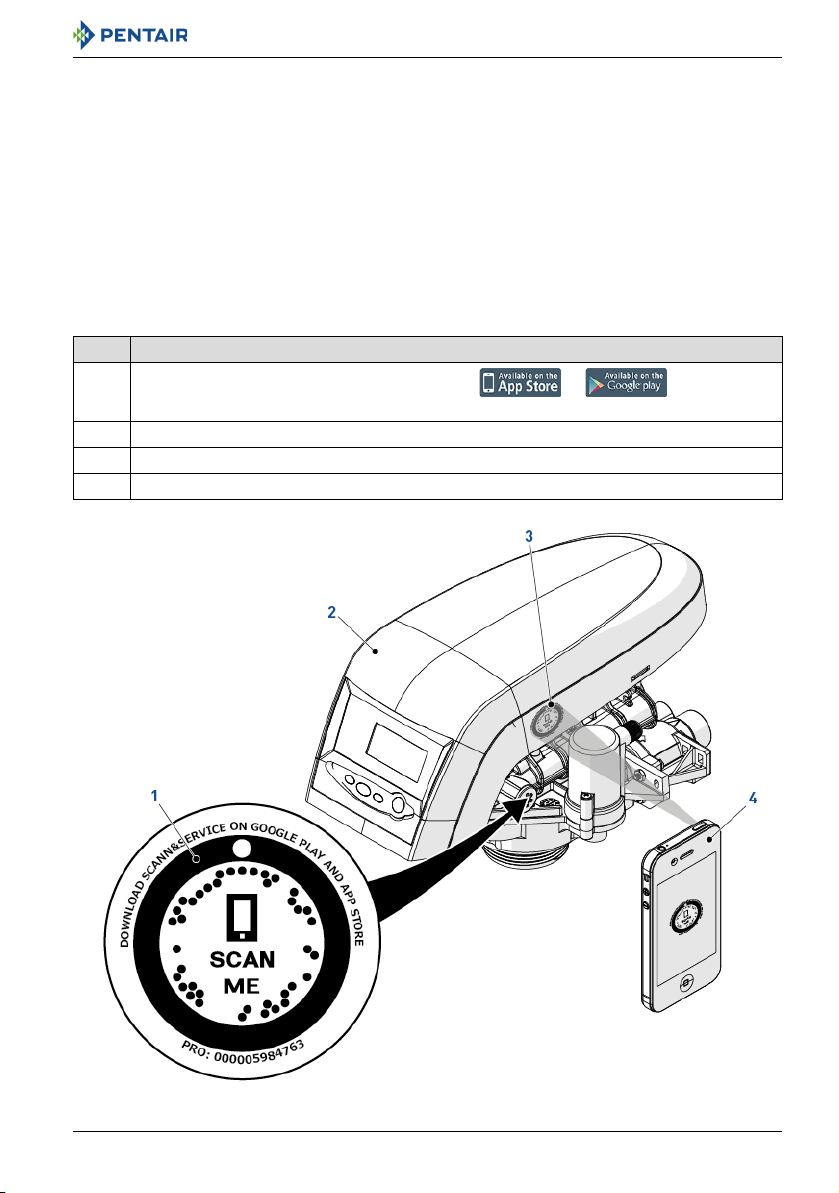
1.10. Scan & Service application
Scan & Service mobile application is the ideal support for the maintenance person in his daily
business. A simple scan of an identification (ID) label (1) present on the valve with a smartphone gives
an instantaneously access to all updated information related to the product, such as:
• valves and tanks detailed configuration;
• manuals;
• spare parts lists;
• troubleshooting recommendations;
• multi-lingual videos, detailing how to best service a part;
• information about new products, latest technologies, novelties about the Blue Network program,
etc....
No. Operation
Download the application "Scan & Service" from or in a
A
smartphone (4).
B Open the application "Scan & Service".
C Scan the bleam (3) stuck on the valve (2).
D Navigate to find information.
Ref. MKT-IM-021 / A - 20.02.2019 9 / 92
Installer Manual 255/LOGIX 742-762-764 - Safety
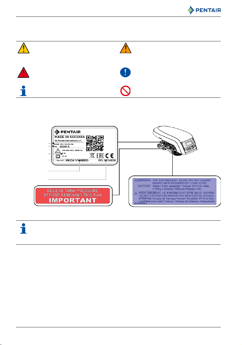
Locking bar label
Model
Serial label
Installation warning
Part number
Electrical
ratings
Serial number
Production
date
Production
order
2. Safety
2.1. Safety pictograms definition
Caution
Warns of a risk of minor injury or major
material damage to the device or
environment.
Danger
Warns against serious personal injury or
death.
Note
Comment.
2.2. Serial label location
Warning
Warns against serious personal injury
and damage to health.
Mandatory
Standard or measure to apply.
Prohibition
Restriction to be observed.
Note
Ensure that the serial label and the safety tags on the device are completely legible and
clean. If necessary, replace them with new tags and put them in the same places.
10 / 92 Ref. MKT-IM-021 / A - 20.02.2019

Installer Manual 255/LOGIX 742-762-764 - Safety
2.3. Hazards
All the safety and protection instructions contained in this document must be observed in order to
avoid temporary or permanent injury, damage to property or environmental pollution.
At the same time, any other legal regulations, accident prevention and environmental protection
measures, as well as any recognized technical regulations relating to appropriate and risk-free
methods of working which apply in the country and place of use of the device must be adhered to.
Any non-observation of the safety and protection rules, as well as any existing legal and technical
regulations, will result in a risk of temporary or permanent injury, damage to property or
environmental pollution.
2.3.1. Personnel
Warning
Only qualified and professional personnel, based on their training, experience and
instruction as well as their knowledge of the regulations, the safety rules and operations
performed, are authorized to carry out necessary work.
2.3.2. Material
The following points must be observed to ensure proper operation of the system and the safety of
user:
• do not remove the locking bar;
• be careful of high voltages present on the transformer (230V);
• do not put your fingers in the system (risk of injuries with moving parts and shock due to electric
voltage).
2.4. Hygiene and sanitization
2.4.1. Sanitary issues
Preliminary checks and storage
• Check the integrity of the packaging. Check that there is no damage and no signs of contact with
liquid to make sure that no external contamination occurred;
• the packaging has a protective function and must be removed just before installation. For
transportation and storage appropriate measures should be adopted to prevent the
contamination of materials or objects themselves.
Ref. MKT-IM-021 / A - 20.02.2019 11 / 92

Installer Manual 255/LOGIX 742-762-764 - Safety
Assembly
• Assemble only with components which are in accordance with drinking water standards;
• after installation and before use, perform one or more manual regenerations in order to clean
the media bed. During such operations, do not use the water for human consumption. Perform a
disinfection of the system in the case of installations for treatment of drinking water for human
use.
Note
This operation must be repeated in the case of ordinary and extraordinary maintenance. It
should also be repeated whenever the system remains idle for a significant time.
Note
Valid only for Italy
signs and obligations arising from the DM25.
: In case of equipment used in accordance with the DM25, apply all the
2.4.2. Hygiene measures
Disinfection
• The materials used for the construction of our products meet the standards for use with potable
water; the manufacturing processes are also geared to preserving these criteria. However, the
process of production, distribution, assembly and installation, may create conditions of bacterial
proliferation, which may lead to odor problems and water contamination;
• it is therefore strongly recommended to sanitize the products. See 7.2. Sanitization, page 60;
• maximum cleanliness is recommended during the assembly and installation;
• for disinfection, use Sodium or Calcium Hypochlorite and perform a manual regeneration.
12 / 92 Ref. MKT-IM-021 / A - 20.02.2019

Installer Manual 255/LOGIX 742-762-764 - Description
3. Description
3.1. Technical specifications
Design specifications/ratings
Valve body ......................................................................... Glass-filled Noryl
Rubber components ......................................................... Compounded for cold water - NSF listed
material
Valve material certification .............................................. WQA Gold Seal Certified to NSF Std. 372
(low lead compliance standard)
Weight (valve with controller)........................................... 1.8 kg
Recommended operating pressure ................................. 1.38 - 8.27 bar
Hydrostatic test pressure................................................. 20.69 bar
Water temperature........................................................... 1 - 38°C
Ambient temperature ....................................................... 2 - 50°C
Flow rates (valve only)
Service at 1.03 bar
(15 psi) drop
(System)
Backwash at
1.72 bar (25 psi)
drop
(per valve)
Service Kv (Cv)
(per valve)
Backwash Kv (Cv)
(per valve)
Single valve
3.52 m3/h 3.52 m3/h 7 m3/h n x 3.52 m3/h
1.36 m3/h 1.36 m3/h 1.36 m3/h 1.36 m3/h
3.4 m3/h
(3.99 gpm)
1 m3/h
(1.2 gpm)
Twin Alternating
(2 valves)
3.4 m3/h
(3.99 gpm)
1 m3/h
(1.2 gpm)
Twin Parallel
(3.99 gpm)
(2 valves)
3.4 m3/h
1 m3/h
(1.2 gpm)
®
- NSF listed material
Lockout "L"
(n valves)*
3.4 m3/h
(3.99 gpm)
1 m3/h
(1.2 gpm)
* n corresponds to the number of valves in the system.
Ref. MKT-IM-021 / A - 20.02.2019 13 / 92

Installer Manual 255/LOGIX 742-762-764 - Description
Valve connections
Tank adapter thread ..........................................................2½" - 8, NPSM
Inlet/outlet maniflold.........................................................1" BSP, female (s. steel) or male
(thermoplastic).
¾" BSP, female (thermoplastic or s. steel) or
male (thermoplastic)
Drain line ...........................................................................½" or ⅜" (manifold dependent)
Brine line ...........................................................................⅜" NPT as standard, ¼" NPT optional;
air check built onto valve
Riser tube [Ø].....................................................................1.050" standard, or 0.8125" optional with
extra insert
Riser tube [length].............................................................1⅛ ± ⅛" above top of tank
Electrical
Controller Operating Voltage ............................................12 VAC (requires use of Pentair Water
supplied transformer)
Input Supply Frequency.....................................................50 or 60 Hz
Motor Input Voltage ...........................................................12 VAC
Controller Power Consumption ........................................8 W (max)
Protection rating................................................................IP23
14 / 92 Ref. MKT-IM-021 / A - 20.02.2019
Installer Manual 255/LOGIX 742-762-764 - Description
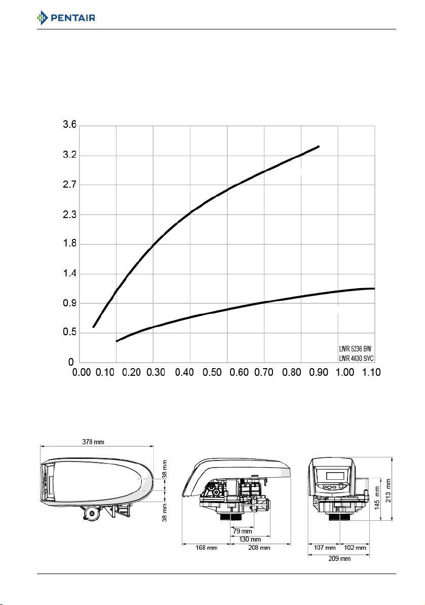
Flow rate (m
3
/h)
Pressure drop (bar)
Backwash
Service
FLOW RATE VS PRESSURE DROP
3.1.1. Performance flow rate characteristics (single valve)
The graph shows the pressure drop created by the valve itself at different flow rates. It makes it
possible to predetermine the maximum flow rate going through the valve depending on the system
settings (inlet pressure etc). It also makes it possible to determine the valve pressure drop at a given
flow rate, and therefore to evaluate the system pressure drop vs flow rate.
3.2. Outline drawing
Ref. MKT-IM-021 / A - 20.02.2019 15 / 92
Installer Manual 255/LOGIX 742-762-764 - Description
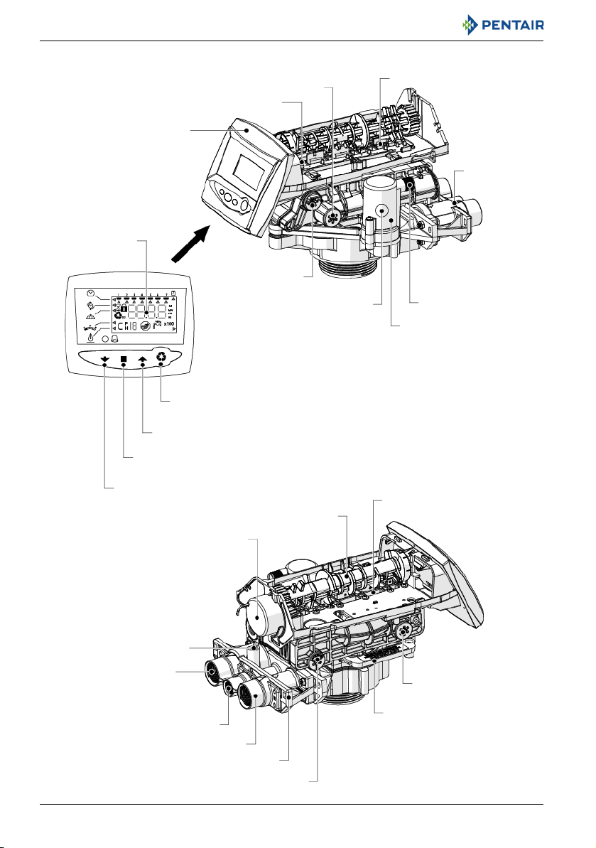
LCD display
DOWN button
SET button
UP button
Manual REGEN button
Control module mount
BLFC/Refill
controller
Injector and cap
Check ball
Air check
Brine tank tube
connection
Manifold
connection
One-piece valve disc spring
Valve discs
Optical sensor
Camshaft
Motor
Turbine cable connection
Drain
Inlet
Backwash flow drain controller
Locking bar
Injector screen
Outlet
Manifold
3.3. Description and components location
16 / 92 Ref. MKT-IM-021 / A - 20.02.2019
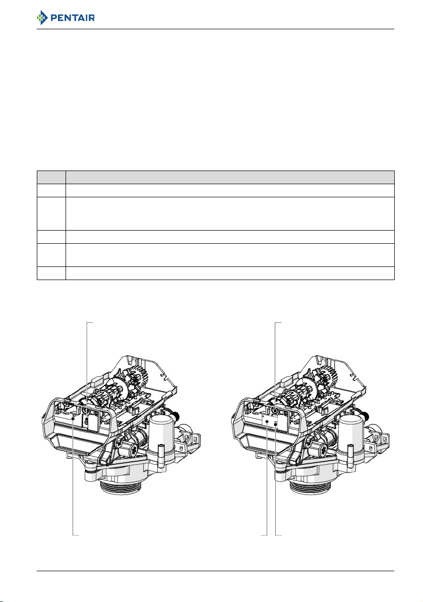
Installer Manual 255/LOGIX 742-762-764 - Description
Hole Camshaft
Switch
Guide pin
Switch cam
3.4. Options available on the valve
3.4.1. Autotrol Logix residential/commercial series auxiliary microswitch kits
The Logix residential/commercial series switch kits allow you to provide an electrical signal during
the valve operation. The switches can be wired independently in N.O or NC. The switches are available
for 0.1 Amp or 5 Amp rating.
3.4.1.1 Front mount
The microswitch is mounted behind the controller at the front end of the camshaft. The cam for this
switch is screwed to the front of the camshaft. This cam can be adjusted to activate the microswitch
on any position upon your needs.
To install this front mount microswitch:
No. Operation
A Place the valve into the position during which you need the signal.
Remove the cover and the controller.
See chapters 9.4.1. First steps, page 69, 9.4.7. Disassembling valve from tank, page 73 and
B
9.4.9. Optical sensor and controller replacement, page 75.
C Screw switch base to top plate using the switch guide pin over screw boss.
Install the cam so that the microswitch pin is released and screw the cam using a self-
D
tapping screw.
E Connect wires.
Ref. MKT-IM-021 / A - 20.02.2019 17 / 92
Installer Manual 255/LOGIX 742-762-764 - Description
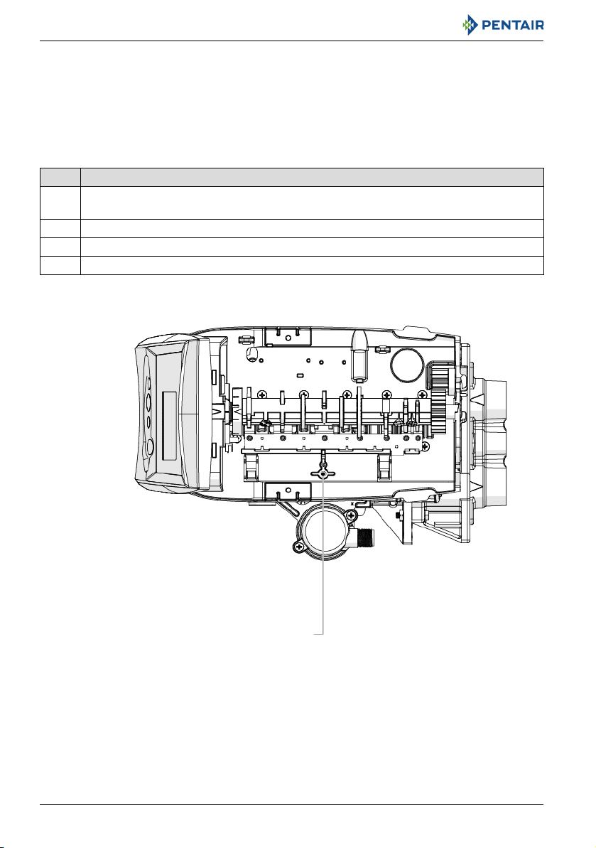
Mounting holes
3.4.1.2 Top plate mount
The microswitch is located under the cover and is screwed to the top plate. The switch is turned on/
off by a cam lobe on the camshaft. Its function is to signal that the unit is in-service or out-of-service
(regenerating). Actually, the microswitch is actuated during service position. As a result, depending
on the wiring N.O or N.C, the signal will be given either during the complete service period or during
the complete regeneration time.
To install this top plate microswitch:
No. Operation
Remove the cover.
A
See chapters 9.4.1. First steps, page 69 and 9.4.7. Disassembling valve from tank, page 73.
B Connect wires.
C Use self-tapping screws to secure the switch base to the blind boss top plate.
D Adjust microswitch distance to the camshaft.
18 / 92 Ref. MKT-IM-021 / A - 20.02.2019

Installer Manual 255/LOGIX 742-762-764 - Description
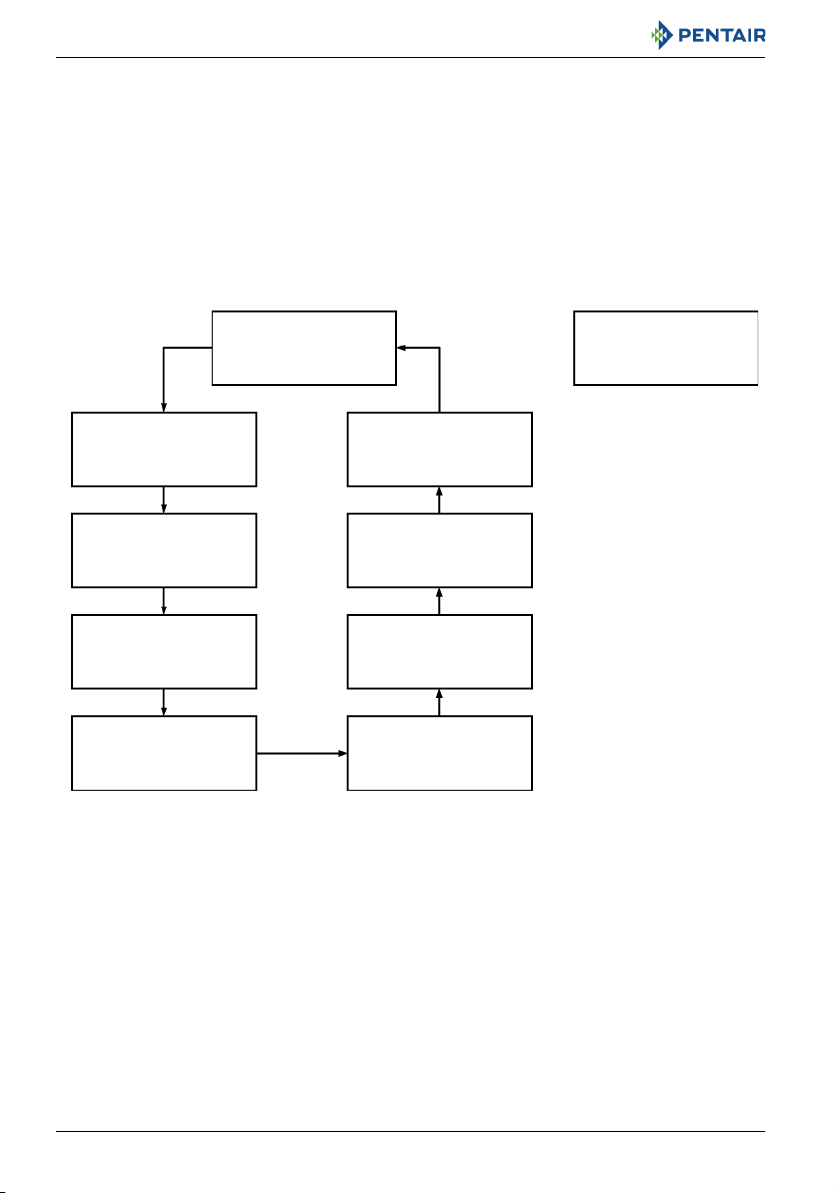
3.5. System regeneration cycle (8-cycles operation)
Service (downflow) — cycle C0
Untreated water is directed down through the resin bed and up through the riser tube. The hardness
ions attach themselves to the resin and are removed from the raw water being exchanged on the resin
beads towards sodium ions. The water is conditioned as it passes through the resin bed.
Backwash (upflow) — cycle C1
The flow of water is reversed by the valve and directed down the riser tube and up through the resin
bed. During the backwash cycle, the bed is expanded and debris is flushed to the drain, while the
media bed is remixed.
Brine (downflow) — cycle C2
The controller directs water through the brine injector and brine is drawn from the brine tank. The
brine is then directed down through the resin bed and up through the riser tube to the drain. The
hardness ions are displaced by sodium ions and are sent to the drain. The resin is regenerated during
the brine cycle. When the air check valve closes brine drawing finishes, and then the slow rinse phase
starts.
Slow rinse (downflow) — cycle C3
Repressurize cycle (hard water bypass flapper open) — cycle C4
This cycle allows the air and water to hydraulically balance in the valve before continuing the
regeneration.
Fast rinse (downflow) — cycle C5
The controller value directs water down through the resin bed and up through the riser tube to the
drain. Any residual brine is rinsed from the resin bed, while the media bed is re-compacted.
2nd Backwash (upflow) — cycle C6
2nd Fast rinse (downflow) — cycle C7
Brine refill — cycle C8
Water is directed to the brine tank at a rate controlled by the refill controller, to create brine for the
next regeneration. During brine refill, treated water is already available at the valve outlet.
Note
For illustration purpose only. Always verify inlet and outlet marking on the valve.
Ref. MKT-IM-021 / A - 20.02.2019 19 / 92
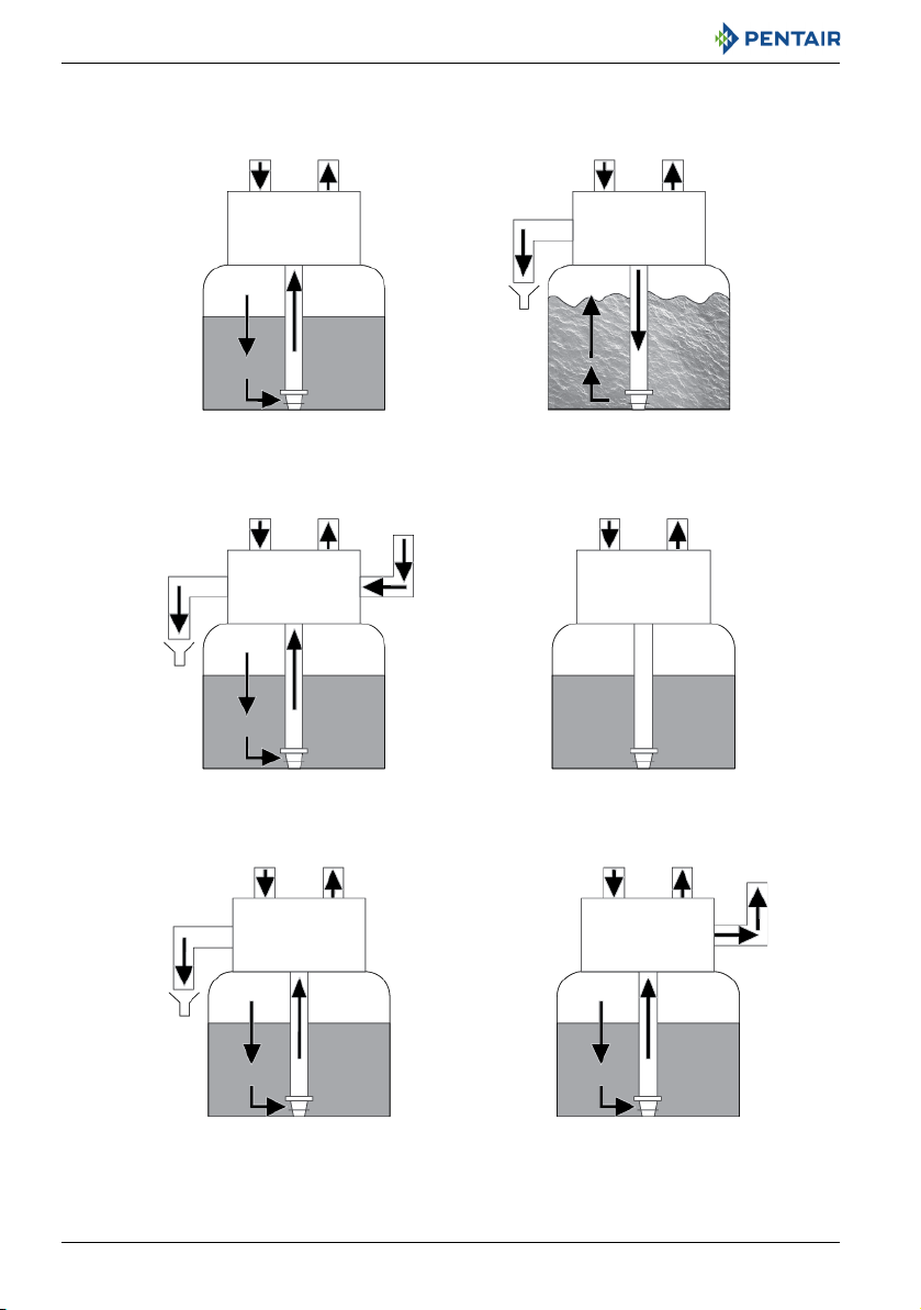
Installer Manual 255/LOGIX 742-762-764 - Description
From brine
tank
To brine
Tank
BRINE/SLOW RINSE
C2 and C3
BACKWASH
C1 and C6
SERVICE
C0
REPRESSURIZE
C4
FAST RINSE
C5 and C7
BRINE REFILL
C8
Valve
Valve
Valve
Valve Valve
Valve
Inlet Outlet Inlet Outlet
Inlet Outlet Inlet Outlet
Inlet Outlet Inlet Outlet
Drain
Drain
Drain
20 / 92 Ref. MKT-IM-021 / A - 20.02.2019
Installer Manual 255/LOGIX 742-762-764 - Description
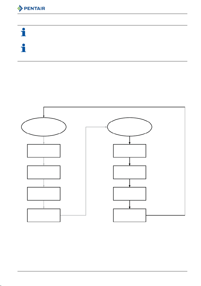
Stand-by
Tank 1 Tank 2
C5
C6
C7
C8
C1
C2
C3
C4
When an immediate regeneration is initiated,
Tank 2 stay in service whereas tank 1 moves to:
Once Tank 1 has reached the service position,
Tank 2 moves to:
Service
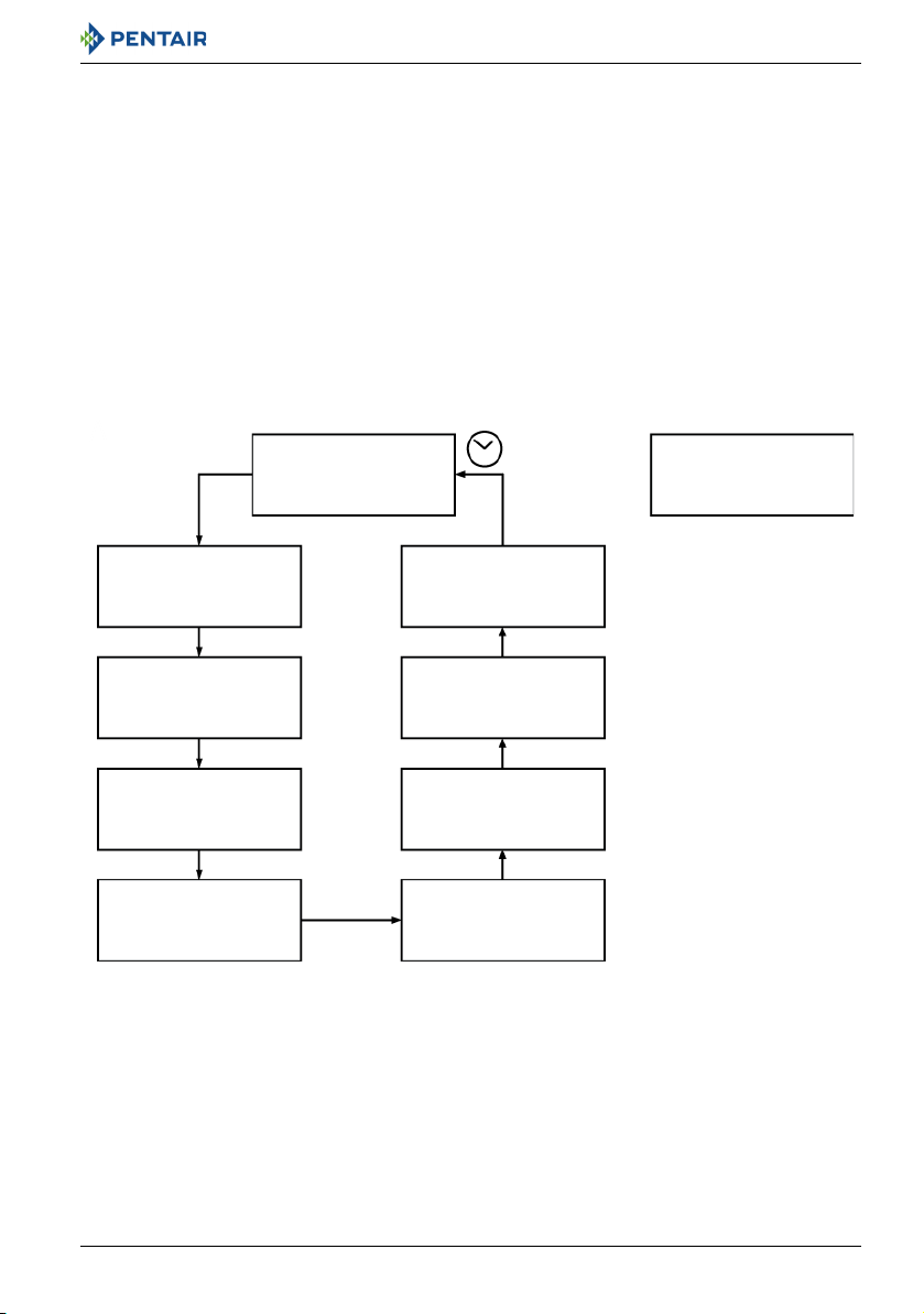
3.6. Regeneration Sequence for Twin and Lockout Systems
Note
Perform a first regeneration for each tank, it will synchronize the camshafts if not already
synchronized.
Note
When you fill water in the system, repeat operations described on chapter 7.1. Water filling,
draining and watertightness inspection, page 58, for each tank.
3.6.1. Twin alternating systems
In this example, tank 1 is in stand-by position whereas tank 2 is in service position.
When an immediate regeneration is initiated, tank 2 stay in service whereas tank 1 moves to C5, C6,
C7, C8 and to the service position.
Once tank 1 reaches the service position, tank 2 moves to C1, C2, C3, C4 and to stand-by position.
Cycles repeat themselves so on.
Ref. MKT-IM-021 / A - 20.02.2019 21 / 92
Installer Manual 255/LOGIX 742-762-764 - Description
Service Service
Tank 1 Tank 2
C1
C2
C3
C4
C8
C7
C6
C5
Tank 2 will not initiate a
regeneration while tank
1 is not back in service
3.6.2. Twin parallel systems
Refill first option: off, Pr=0
Tank 1 and tank 2 are both in service position. Depending on the residual capacity, tank 1 or tank 2 will
initiate first a regeneration.
In this example tank 1 moves from service position to C1, then to C2, ... until C8 and comes back in the
service position. Tank 2 will not initiate a regeneration while tank 1 is not back in service.
Initiate again a regeneration, this time tank 2 will move through the cycles whereas tank 1 stay in
service.
22 / 92 Ref. MKT-IM-021 / A - 20.02.2019
Installer Manual 255/LOGIX 742-762-764 - Description
Service Service
Tank 1 Tank 2
C1
C2
C3
C4
C8
C7
C6
C5
Tank 2 will not initiate a
regeneration while tank 1 is
not back in service
2 hours
Refill first option: on, Pr=1
The refill first option has been designed mainly for twin parallel systems using only one brine tank. It
allows a minimum time of 2 hours for brine to be saturated.
Tank 1 and tank 2 are both in service position. Depending on the residual capacity, tank 1 or tank 2 will
initiate first a regeneration.
In this example tank 1 moves from service position to C8 and then comes back in the service position
for 2 hours. "C0" will then be displayed. After this delay the valve will then regenerate normally but
skipping the C8 cycle since the refill will be done first at the next regeneration.
Tank 2 will not initiate a regeneration while tank 1 is not back in service.
Initiate again a regeneration, this time tank 2 will move through the cycles whereas tank 1 stay in
service.
Ref. MKT-IM-021 / A - 20.02.2019 23 / 92

Installer Manual 255/LOGIX 742-762-764 - Description
Service Service
Tank 1 Tank 2
C1
C2
C3
C4
C8
C7
C6
C5
Others tanks will not initiate a
regeneration while tank 1 is not back in
service
Tank X
Service
...
3.6.3. Lockout "L" systems
The first tank of the system whose capacity is exhausted will be regenerated first. The tank controller
will send a signal to all others controllers in the system that will not be able to start a regeneration
until it is finished.
The others tanks will then regenerate in order of priority according to the remaining capacity.
When you order a 255 - 764L valve, it will be shipped with a standard 255 Logix camshaft. This
camshaft does not close the bypass flapper during regeneration, so there will be hard water available
at the outlet during all the regeneration. If you are building a multi-simplex system with 255 - 764L
valves and you do not want hard water to be bypassed during the regeneration, use one of the
following options :
• Use the 255 Logix duplex camshaft on each valve in the system. This camshaft ensures that the
bypass flapper is closed during all the regeneration process. The backwash is then done with
treated water of another tank entering through the valve outlet (same principle as for a duplex
mode A or P). If you choose this option, do not forget to take into account this additional flow to
be produced in service when sizing your installation.
Use a solenoid valve on the valve output and a microswitch kit. The microswitch is mounted on the
camshaft and it closes the solenoid valve for the duration of the regeneration. Therefore the valve will
not use water coming from the others tanks.
24 / 92 Ref. MKT-IM-021 / A - 20.02.2019

Installer Manual 255/LOGIX 742-762-764 - System sizing
4. System sizing
4.1. Recommendations
4.1.1. Injector/DLFC/Refill flow controler-Valve configuration
Vessel diameter
[In]
6 5/10 E [yellow] 0.33 0.9
7 15 F [peach] 0.33 1.2
8 20 G [tan] 0.33 1.6
9 30 H [lt purple] 0.33 2.0
10 35 J [lt blue] 0.33 2.5
12 40 K [pink] 0.33 3.5
13 50 L [orange] 0.33 4.1
14 80 L [orange] 0.33 4.8
Media volume
[L]
Injector Flow
control
Refill flow control
[gpm]
4.2. Cycle time calculation
All the Logix controller range automatically calculates the unit capacity as well as the cycle time.
No calculations are therefore required.
Backwash flow
control
[gpm]
Ref. MKT-IM-021 / A - 20.02.2019 25 / 92

Installer Manual 255/LOGIX 742-762-764 - System sizing
TOTAL
Inlet pressure [bar]
Injector "F" (Peach)
For 7" Tanks
Injector "G" (Tan)
For 8" Tanks
Injector "H" (Light Purple)
For 9" Tanks
Flow rate [l/min]
RINSEBRINE DRAW
Injector "E" (Yellow)
For 6" Tanks
Inlet pressure [bar]
Flow rate [l/min]
Inlet pressure [bar]
Flow rate [l/min]
Inlet pressure [bar]
Flow rate [l/min]
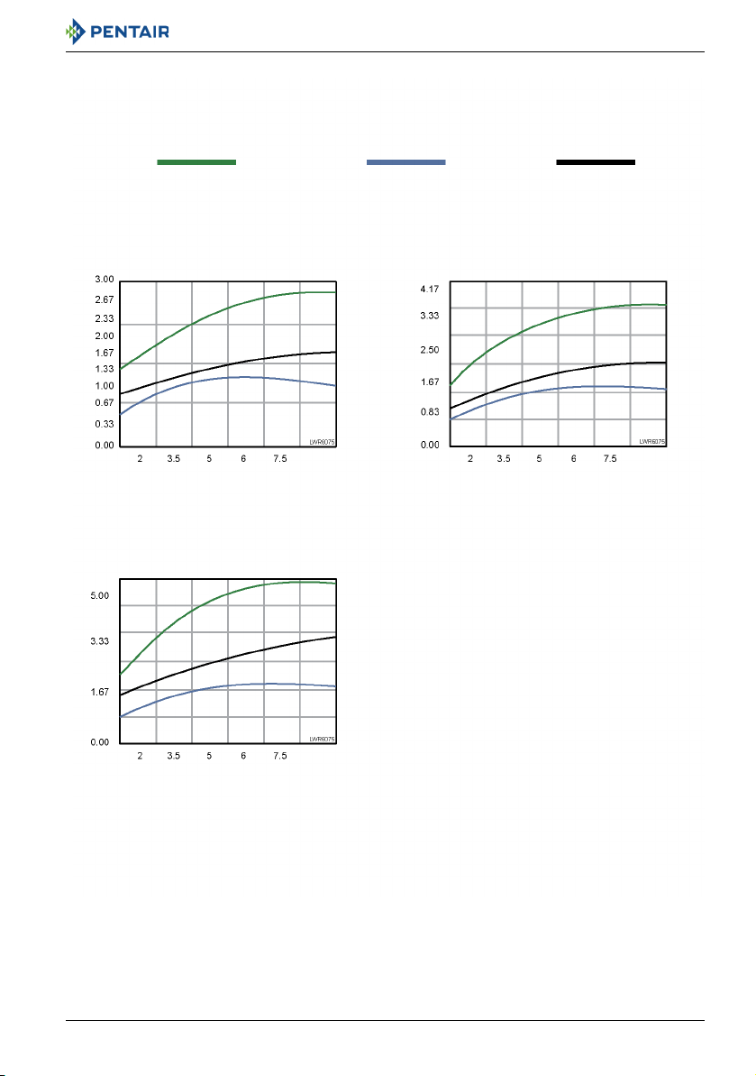
4.3. Injector flow rates
The following tables represent the injectors flow rate as a function of the inlet pressure for the
different injector sizes.
26 / 92 Ref. MKT-IM-021 / A - 20.02.2019
Installer Manual 255/LOGIX 742-762-764 - System sizing
Injector "K" (Pink)
For 12" Tanks
Injector "L" (Orange)
For 13 " and 14" Tanks
Injector "J" (Light Blue)
For 10" Tanks
TOTAL RINSEBRINE DRAW
Inlet pressure [bar]
Flow rate [l/min]
Inlet pressure [bar]
Flow rate [l/min]
Inlet pressure [bar]
Flow rate [l/min]
Ref. MKT-IM-021 / A - 20.02.2019 27 / 92

Installer Manual 255/LOGIX 742-762-764 - System sizing
4.4. Resin exchange capacity upon salt dosage for standard efficiency
Salt amount Corresponding resin exchange capacity
grams /
liter of resin
50 29.9 2.99 1.67
60 34 3.4 1.9
70 37.5 3.75 2.09
80 40.6 4.06 2.27
90 43.4 4.34 2.42
100 45.9 4.59 2.56
110 48.2 4.82 2.69
120 50.2 5.02 2.8
130 52.1 5.21 2.91
140 53.8 5.38 3.01
150 55.5 5.55 3.1
170 58.5 5.85 3.27
200 62.7 6.27 3.5
230 66.9 6.69 3.74
260 71 7.1 3.97
290 75.3 7.53 4.21
grams /
liter of resin as CaCO
°f.m3 /
3
liter of resin
°d.m3 /
liter of resin
28 / 92 Ref. MKT-IM-021 / A - 20.02.2019
 Loading...