

Page 1
LINEGUARD UF100
COMPACT WATER SYSTEMS
POINTOFENTRY
MANUAL
MAN LINEGUARD UF-100 EN 0315
ADVANCED FILTRATION LINEGUARD
Page 2

LINEGUARD UF100
COMPACT WATER SYSTEMS
INSTALLATION & OPERATING MANUAL
CONTENTS
1 Introduction __________________________________________________________________ 1
1.1 Important precautions _________________________________________________________________1
1.2 Parts included ________________________________________________________________________1
1.3 Tools and materials required for installation _______________________________________________1
2 How the LineGuard works ________________________________________________________ 2
2.1 Filtration mode _______________________________________________________________________2
2.2 Cleaning cycles _______________________________________________________________________2
2.3 Parallel installation of multiple LineGuards _______________________________________________3
3 Installation of the LineGuard ______________________________________________________ 4
3.1 Mounting the LineGuard _______________________________________________________________4
3.2 Piping installation _____________________________________________________________________4
3.3 Electrical connection __________________________________________________________________6
3.4 Mounting the module(s) ________________________________________________________________6
3.5 Start-up procedure ____________________________________________________________________7
4 Control unit settings ____________________________________________________________ 8
4.1 Operating mode ______________________________________________________________________8
4.2 Info menu ___________________________________________________________________________8
4.2.1 Displaying the volumes ___________________________________________________________9
4.2.2 Displaying the service and module date ______________________________________________9
4.2.3 Displaying the performance ______________________________________________________10
4.3 Setup menu _________________________________________________________________________10
4.3.1 General settings ________________________________________________________________11
4.3.1.1 Setting the language _______________________________________________________11
4.3.1.2 Setting the clock ___________________________________________________________11
4.3.1.3 Setting the date ___________________________________________________________12
4.3.1.4 Setting the module surface area______________________________________________12
4.3.2 Changing the flush settings_______________________________________________________12
4.3.2.1 Setting the start time _______________________________________________________13
4.3.2.2 Setting the cleaning cycle interval ____________________________________________13
4.3.2.3 Setting the duration of the forward flush _______________________________________13
4.3.2.4 Setting the backwash _______________________________________________________14
EN
Page 3

4.3.2.5 Setting the volume flush ____________________________________________________14
4.3.2.6 Setting the flux flush _______________________________________________________14
4.3.2.7 Setting an overruling flush __________________________________________________15
4.3.3 Setting the alarm _______________________________________________________________15
4.3.3.1 Setting the time alarm ______________________________________________________15
4.3.3.2 Setting the volume alarm ___________________________________________________16
4.3.3.3 Setting the flux alarm ______________________________________________________16
4.3.4 Start-up program _______________________________________________________________16
4.3.5 Factory default settings __________________________________________________________17
1 INTRODUCTION
Thank you for choosing a LineGuard UF-100 water filtration system. Please refer to the product datasheet for
details on performance, conditions of use, and storage and handling of this product.
The LineGuard has been specifically designed to remove viruses, bacteria, cysts and protozoa such as
Cryptosporidium, Giardia, and Legionella from your drinking water, while allowing healthy, natural minerals
to pass through. It will also eliminate any turbidity from your drinking and shower water.
1.1 Important precautions
5 Maintenance _________________________________________________________________ 18
5.1 General inspection ___________________________________________________________________18
5.2 Testing and replacing the modules ______________________________________________________18
5.2.1 Integrity testing modules _________________________________________________________18
5.2.2 Timing ________________________________________________________________________18
5.2.3 Draining the system _____________________________________________________________19
5.2.4 Dismounting the used modules ___________________________________________________19
5.2.5 Mounting the module(s) __________________________________________________________19
5.3 Control Unit – optimizing the settings ___________________________________________________20
6 Dimensions _________________________________________________________________ 21
7 Clearances __________________________________________________________________ 22
8 Piping schematics _____________________________________________________________ 23
9 Technical Information __________________________________________________________ 24
10 Limitation of warranty and liability _______________________________________________ 25
1. The LineGuard system is intended for indoor use only.
2. The LineGuard system is only suitable for municipal (treated) water and cold or mixed water lines. The
maximum permitted operating temperature is 50 ˚C/122 ˚F.
3. The maximum operating pressure of the filter system is 4 bar/58 psi. It is recommended to install a
pressure controll valve and a pressure relief valve that relieves water pressure above 4 bar/58 psi to the
drain of the system. Please check with your water company or pump supplier for information on the
existing water pressure.
4. If the LineGuard is mounted in a water system already in use, please make sure to disinfect the piping
after the filter system.
5. Protect against freezing after first use.
6. Handle with care, do not expose to shocks.
7. Please check your national plumbing codes and ensure that you follow those guidelines when installing
the water filtration system.
8. Make sure the filtration system is properly connected in the water system by closely following the
instructions in this manual.
9. The room where the LineGuard is installed should be provide with an water barrier and drain.
1.2 Parts included
• LineGuard (frame and control unit)
• Membrane modules (2 pcs)
1.3 Tools and materials required for installation
• Hexagon key 4 mm
• Hexagon key 5 mm
ENEN
1
Page 4

2 HOW THE LINEGUARD WORKS
2.1 Filtration mode
The LineGuard membrane modules contain hundreds of capillary ultrafiltration (UF) membranes. The
porous walls of these hollow fibers contain billions of microscopic pores which act as an ultra-fine sieve.
The water pressure pushes water molecules and vital minerals from the inside-out through the pores
of the membrane fibers, while retaining larger contaminants such as bacteria, parasites and viruses.
Automated cleaning cycles periodically flush out the contaminants retained inside the membranes. Once
the LineGuard has been installed on the main water supply line, the water is filtered by the membrane
modules.
2.2 Cleaning cycles
Contaminants in the water foul the inner surface of the membranes, which affect the performance of the
system. The LineGuard is equipped with a control unit that sets automated cleaning cycles so that this
fouling is periodically flushed out. There are two types of cleaning cycles: a forward flush and a backwash.
In a forward flush the membranes are flushed with feed water. The feed water flows through the inner
part of the membranes at a much greater speed than in the filtering mode. Because of this high flow and
the resulting turbulence, the fouling on the membrane is released and discharged. The flush water is
discharged to the system drain. Particles that are caught in the membrane pores are not released and can
only be removed with a backwash. Please note that the backwash needs backpressure from the water line
after the system for an optimal cleaning cycle. Whenever the LineGuard discharges to an open system, like
a water tank, the backwash will be not be performed at an optimal level.
A flow sensor will prevent the system from flushing when in use. Whenever water is used at the moment of
a scheduled cleaning cycle the system will wait and resume the cleaning cycle 30 seconds after the water
usage has stopped.
Whenever large quantities of water are used, additional cleaning cycles should be performed. This is done
by setting a flush volume in the control unit. Upon reaching this volume a cleaning cycle will be performed. A
volume flush will overrule the normal flush interval.
Whenever low quality feed water is used, the performance of the system might decrease rapidly. The
performance of a filter module is determined by the “flux” (defined as the quantity of permeate that passes
through the membrane surface per amount of time).
A cleaning cycle can also be performed by setting a flux flush. For example, when a flux flush of 10% is set, a
cleaning cycle will be performed when the flux over the filter modules is decreased by 10%. A flush flux will
overrule the normal flush time interval. A cleaning cycle will take place whenever the flush volume or flux
flush is reached. After the cycle, these settings will be reset.
2.3 Parallel installation of multiple LineGuards
A LineGuard UF-100 has a initial flow rate of 60 l/min (3.6 m3/h). In case more capacity is needed,
parallel installation of up to five LineGuard systems is possible. Please contact your installation company
for details and a preferred installation scheme.
In case multiple LineGuards are installed, they will be part of bigger installation which might have a
constant demand for water that will permantently overrule the flushing cycles. This will have a negative
influence on performance of the system. In this case a flushing overrule should be set (see 4.3.2.7).
The flushing cycles of multiple LineGuard need to be set out-of-phase (see 4.3.2.1)
A backwash is performed by reversing the filtration process. Filtered water (or permeate as it is called)
is flushed from the outside to the inside of the membranes. This way, particles that are caught in the
membrane pores are released and discharged. In a backwash the LineGuard uses permeate from one
module to backwash the other so that the modules will not foul at the ‘clean side’. The flush water is
discharged to the system.
The LineGuard is set to automatically perform one 30 second flush cycle a day at 01:00 am. Frequency,
duration and time can be adjusted by setting the control unit of the system. The optimal duration and
frequency of the flush cycle depends on the water quality and usage. On average one flush per day should
be sufficient. Your installation company can advise you on the right settings.
2 3
ENEN
Page 5
3 INSTALLATION OF THE LINEGUARD
1 - Drain
The LineGuard membrane filtration system should be installed in the main water supply line near its entry
into the building. It should be placed at any point past the main shut-off valve, before the pipes branch off
into multiple directions.
This manual provides general guidelines for the installation. Please keep in mind that the installation must
always comply with all local and national plumbing guidelines and should be carried out by a certified
installation company.
3.1 Mounting the LineGuard
The LineGuard should be attached to the wall with suitable fasteners. The wall has to be flat and the
material must be strong enough to support the LineGuard. In order to allow enough built-in space for the
water pipes and for the display to be at a readable height it is recommended to mount the LineGuard at
600 mm (2 feet) above floor level. At least 100 mm (4 inches) of clear space is recommended at the top for
releasing the modules.
3.2 Piping installation
The LineGuard membrane filtration system should be placed on the main water supply line near its entry
into the building. It can be situated at any point past the main shut-off valve, but before the pipes branch off
into multiple directions. To install the LineGuard, three 22 mm pipe ends must be connected. See the figure
below. An adapter 22 mm to 3/4 inch is included.
Please review the recommended piping schematic below for a correct installation. A full installation scheme
is included in the back of this manual. Please note that any alteration to this might lead to problems with
servicing the LineGuard.
4
3B 1B
3A 1A
2
8
67
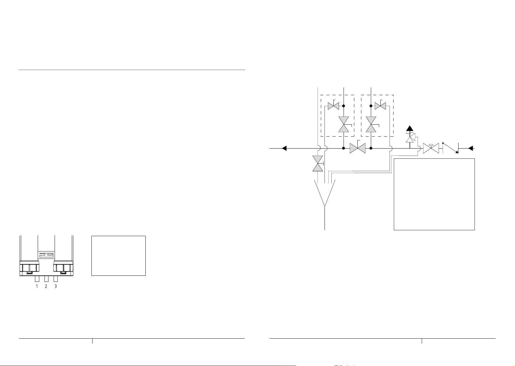
1 - Feed water shut-off valve (1A)
with integrated drain valve (1B)
2 - Bypass valve
3 - Filtered water shut-off valve (3A)
with integrated drain valve (3B)
5
4 - Drain valve
5 - Drain
6 - Back flow preventor
(acc, EN 1717: BA, CA or EA)
7 - Pressure reducing valve
8 - Pressure relief valve
All above mentioned appendages are not
included with the LineGuard
Figure 2: Partial piping schematic
2 - Filtered water
3 - Feed water
ø 22 mm pipe ends
(adapter to 3/4 inch is included)
A shut-off valve should be placed directly on both the feed and filtered water pipes of the LineGuard (figure 2,
position 1 and 3). A shut-off valve with an integrated drain valve is recommended for ease of installation.
We strongly recommend using a fully integrated controllable check valve (a backflow preventor) at the feed
water side. This offers a efficient protection against pollution of the drinking water system.
The maximum system pressure should not exceed 4 bar. In case of potentially higher water pressure, a
pressure reducing and relief valve (figure 2, position 7 and 8) must be installed between the main shut-off
valve and the LineGuard. The diameter of the drain should at least be two pipe diameters (44 mm or 2 inch).
Figure 1: Connecting the LineGuard
Warning: before installing the LineGuard please thoroughly disinfect the piping structure behind the
LineGuard. Any biofilm that may be in the piping could contaminate the filtered water from the LineGuard!
Please note that the capacity of the drain should be large enough to discharge the flow during flushing
cycles. A ‘rule of thumb’ in this: measure the flow of the waterline system without mounting the
LineGuard (the maximum flow at this point of the system). The capacity of the drain should at least meet
that flow. If this is somehow not possible, we advise you to mount a valve on the drain pipe. You should
set this valve during the start-up procedure (see 3.5). Make sure you seal this valve afterwards.
4 5
ENEN
Page 6

3.3 Electrical connection
The electrical connection to the control unit power supply and the ground/earth connection should be made
by qualified personnel.
Grounding terminal
Figure 3: Position of the earth/ground connection
IMPORTANT - Make sure the power supply is not disconnected or disrupted for more than 24 hours. When
the LineGuard is without power the cleaning cycles will not be executed, which may lead to a premature
reduction in performance.
3.4 Mounting the module(s)
Please follow the steps below in order to mount the modules in the LineGuard.
1. Remove the M6 bolt at the top of the system.
2. Remove the locking strip at the top of the system.
3. Take the module out of the sealed bag.
4. Remove the seal caps from the connector and the valve block
5. Place the module into the bottom bracket.
6. Press the module with the connectors into the valve block.
7. Place the locking strip into place.
8. Place and tighten the M6 bolt to prevent the locking strip from unlocking.
3.5 Start-up procedure
After the LineGuard has been fitted into the waterline a start-up procedure must be carried out. The
membranes in the ultrafiltration module are preserved with glycerin, which must be flushed out first. Under
no circumstances should the glycerin enter the piping network. Start-up procedure:
• Close all the shut-off valves (figure 2, position 1A/2/3A).
• Open the drain valve (3B and 4).
• Slowly open the feed water valve (position 1A). The filtration module will now gradually fill with water.
• When water comes out of the drain valve (3B), close the drain valve.
• Run the start-up program (see 4.3.4).
• If the drain capacity is too low, water will come out of the drain opening. Set the drain valve (4) to prevent
this from happening. Make sure you seal this valve afterwards.
• After completing the start-up procedure, open the drain port at the filtered water valve (position 3B).
• Allow the water to run for 1 minute from the drain valve.
• Close the drain valve (position 3B).
• Open the filtered water valve (3A).
• The LineGuard is now ready for use.
• Refer to chapter 4 to setup the control unit.
3B 1B
3A 1A
8
2
4
1 - Feed water shut-off valve (1A)
with integrated drain valve (1B)
67
2 - Bypass valve
3 - Filtered water shut-off valve (3A)
with integrated drain valve (3B)
5
4 - Drain valve
5 - Drain
6 - Back flow preventor
(acc, EN 1717: BA, CA or EA)
7 - Pressure reducing valve
8 - Pressure relief valve
All above mentioned appendages are not
included with the LineGuard
6 7
ENEN
Page 7

4 CONTROL UNIT SETTINGS
4.2.1 Displaying the volumes
4.1 Operating mode
When in use, the control unit displays the actual mode of the system. In case no water is used the following
text appears on the display:
During filtration, the stand-by mode and the flow in l/min are displayed:
During a cleaning cycle, the flushing mode and the action performed is displayed:
Flushing 4: Forward flushing the left module
Flushing 3: Forward flushing the right module
Flushing 2: Backwashing the left module
Flushing 1: Backwashing the right module
4.2 Info menu
In the info menu press /\ or \/ until the screen below appears:
The total volume of filtered water since the system has been in use is displayed by pressing show
The total volume of water filtered since the last time it was serviced is displayed by pressing ok.
The total volume of filtered water is displayed by pressing ok.
This shows the total volume of filtered water since the last module change date.
Exit the volume menu by pressing ok or exit
4.2.2 Displaying the service and module date
This menu displays information regarding treated volumes, service date and performance. In the operating
In the info menu press /\ or \/ until the screen below appears:
status menu press menu and then press /\ or \/ until the screen below appears:
The date of the last time the system was serviced is displayed by pressing show.
This date can be changed by pressing set. This should be done after every system service.
8 9
ENEN
Page 8

The date of the last time the modules were replaced is displayed by pressing \/.
This date can be changed by pressing set. This should be done after every module replacement.
Exit the service info menu by pressing exit.
4.2.3 Displaying the performance
In the info menu press /\ or \/ until the next screen appears:
The performance of the system is displayed by pressing show.
4.3.1 General settings
In this menu, language, clock, date and module specifications can be set. In the setup menu, press /\ or \/
until the screen below appears:
4.3.1.1 Setting the language
In the general settings menu press /\ or \/ until the screen below appears:
The language can be changed by pressing set.
Select the preferred language by pressing the - and + buttons and press ok. Optional languages are English,
German and Spanish.
4.3.1.2 Setting the clock
The following data is now displayed:
In the general settings menu press /\ or \/ until the screen below appears:
F = current flow in l/min
J = current flux in l/(m2.h.b)
Pi = pressure at the feed water side in bar
Po = pressure at the filtered water side in bar
The time on the clock can be set by pressing set. First set the hours by pressing the - and + buttons and
4.3 Setup menu
press ok. Then set the minutes by pressing the - and + buttons and close by pressing ok.
In this menu all the settings of the LineGuard can be defined.
In the operating mode menu press menu and then press /\ or \/ until the next screen appears:
10 11
ENEN
Page 9

4.3.1.3 Setting the date
4.3.2.1 Setting the start time
In the general settings menu press /\ or \/ until the screen below appears:
The date can be changed by pressing set.
First set the days by pressing the - and + buttons and press ok. Then set the month by pressing the - and +
buttons. Finally set the year by pressing the - and + buttons and close by pressing ok.
4.3.1.4 Setting the module surface area
The surface area of the membrane modules is preset in the factory. This only needs to be changed whenever
the modules are replaced with another type.
In the general settings menu press /\ or \/ until the screen below appears:
The surface area can be changed by pressing set. Set the surface area by pressing the - and + buttons and
press ok.
4.3.2 Changing the flush settings
In the flush settings menu all the parameters concerning cleaning can be changed.
In the setup menu press /\ or \/ until the screen below appears:
The default start time of the cleaning cycle is 01:00 (1:00 am).
In the flush setting menu press /\ or \/ until the screen below appears:
The start time can be changed by pressing set.
First set the hours by pressing the - and + buttons and press ok. Then set the minutes by pressing the - and
+ buttons and close by pressing ok. In case multiple LineGuards are installated in parallel, the start time of
the cycles needs to be set out-of-phase with a 15 minutes time difference.
4.3.2.2 Setting the cleaning cycle interval
The default cleaning cycle interval is one day. During low usage periods (if little or no water is being used)
the interval can be changed to, for example, seven days.
In the flush setting menu press /\ or \/ until the next screen appears:
The interval can be changed by pressing set.
Set the interval by pressing the - and + buttons and press ok.
4.3.2.3 Setting the duration of the forward flush
The forward flush is the duration in seconds the modules are forward flushed.
The default value of the duration of the forward flush is 10 seconds. In case of low quality water the duration
should be increased. In the flush setting menu press /\ or \/ until the screen below appears:
The duration of the forward flush can be changed by pressing set.
12 13
Set the duration by pressing the - and + buttons and press ok.
ENEN
Page 10

4.3.2.4 Setting the backwash
4.3.2.7 Setting an overruling flush
The default value of the duration of the backwash is 20 seconds. In case of low quality water the duration
should be increased. In the flush setting menu press /\ or \/ until the screen below appears:
The back wash duration can be changed by pressing set.
Set the duration by pressing the - and + buttons and press ok.
4.3.2.5 Setting the volume flush
The volume flush is performed whenever a large quantity of water is filtered in between the cleaning cycles.
The default value of this volume is 99.9 m3 (26,400 gal). The volume flush overrules the interval period that
has been set. In the flush setting menu press /\ or \/ until the screen below appears:
The volume can be changed by pressing set.
Set the volume by pressing the - and + buttons and press ok.
4.3.2.6 Setting the flux flush
The flux flush is performed whenever low quality water is filtered causing a drop in the flux of the modules.
The default value of this flux is 100%. This means that a cleaning cycle will be executed when the flux after
the last cycle has been decreased by 100%. A suitable value for the flux flush will be between 10 and 20%.
The flux flush overrules the interval period that has been set.
In the flush setting menu press /\ or \/ until the screen below appears:
In case multiple LineGuards are installed in parallel, an overruling flush should be set. Please contact your
installation company on details for these settings.
4.3.3 Setting the alarm
In the alarm settings menu an alarm warning can be set upon reaching a certain period of time after the
service date or upon reaching a certain volume of filtered water or whenever a predefined minimum flux is
reached. An alarm warning will be displayed in the control unit. For example:
4.3.3.1 Setting the time alarm
In the operating mode menu press menu and then press /\ or \/ until the screen below appears:
The time alarm will display a message upon reaching a certain period of time after the service date. The
default value of the time alarm is 12 months.
In the setup menu press /\ or \/ until the next screen appears:
The time can be changed by pressing set.
Set the time by pressing the - and + buttons and press ok.
The flux can be changed by pressing set.
Set the flux by pressing the - and + buttons and press ok.
14 15
ENEN
Page 11

4.3.3.2 Setting the volume alarm
START-UP PROGRAM
The volume alarm will display a message upon reaching a certain volume of filtered water. The default value
of the volume alarm is 999 m3 (264,000 gal).
In the setup menu press /\ or \/ until the next screen appears:
The volume can be changed by pressing set.
Set the volume by pressing the - and + buttons and press ok.
By pressing run, the LineGuard will flush away the glycerin for 8 minutes. This is necessary only once
whenever a new membrane module is put into use. After the start-up cycle is complete the control unit will
automatically return to the setup menu.
4.3.5 Factory default settings
This setting will return the LineGuard settings to the original factory defaults. Please be aware that all data
such as treated volume will be lost!
In the setup menu press /\ or \/ until the screen below appears:
4.3.3.3 Setting the flux alarm
The settings can be reset to factory default values by pressing set. You will be asked to confirm your choice in
the screen below that will appear.
The flux alarm will display a message upon reaching a certain minimum flux. The default value is 000 l/
(m2.h.b).
In the setup menu press /\ or \/ until the next screen appears:
Press yes if you are sure you want to reset to factory default values.
The flux can be changed by pressing set.
Set the flux by pressing the - and + buttons and press ok.
4.3.4 Start-up program
By carrying out the start-up procedure in Section 3.5 the LineGuard will be ready for use. The membranes
in the UF module are preserved with glycerin, which must be flushed away first. Under no circumstances
should the glycerin enter the network of pipes.
In the setup menu press /\ or \/ until the screen below appears:
exit \/ /\ run
16 17
ENEN
Page 12

5 MAINTENANCE
5.1 General inspection
The following parts should be visually yearly checked for malfunctions scaling, rust or any other visible signs
of deterioration.
• Frame
• Magnetic Valves
• Flow Switch
• Pressure Sensors
• Electrical Connection
• Control Unit
5.2 Testing and replacing the modules
5.2.1 Integrity testing modules
Execute an yearly integrity test according the procedure Integrity test LineGuard.
5.2.2 Timing
The UF modules should be replaced when the system pressure drop becomes too high and the output starts
to decrease. This depends largely on the feed water quality and the amount of water used. The service
interval should be set according to this. When the LineGuard needs maintenance, one of the following text
messages will appear in the display:
Refer to 4.2.2 for changing the service date.
5.2.3 Draining the system
Before the modules can be replaced the LineGuard needs to be drained of any water resting in the piping of
the system. This can be done by following the steps below:
1. Close the feed water shut-off valve (figure 2, position 1A)
2. Close the filtered water shut-off valve (position 3A)
3. Slowly open the feed and filtered water drain valve (position 1B and 3B) and carefully release
any pressure left in the system.
5.2.4 Dismounting the used modules
Although the LineGuard has been drained, there will still be some water left inside the modules. Use a
bucket to collect this water.
Please follow the steps below to dismount the modules:
1. Loosen and remove the M6 bolt at the top of the module.
2. Remove the locking strip at the top of the module while holding the module to prevent it from
falling out of the system.
3. Pull the module out of the valve block and lift the module out of the bracket at the bottom.
4. Place the used module in a plastic bag and seal for transport and storage.
5.2.5 Mounting the module(s)
Before mounting the new modules please make sure that you thoroughly disinfect the module connectors
and the valve block openings by spraying them a few times with Norit H2OK Sanitizer Spray.
Please follow the steps below in order to mount the modules in the LineGuard. Before mounting the
modules please make sure that these are the correct versions.
1. Take the module out of the sealed bag.
2. Remove the seal caps from the connector and the valve block.
3. Place the module into the bottom bracket.
4. Press the module with the connectors into the valve block.
5. Place the locking strip into place.
6. Place and tighten the M6 bolt to prevent the locking strip from unlocking.
18 19
ENEN
Page 13

5.3 Control Unit – optimizing the settings
2101156
The LineGuard is automatically set to perform one flush cycle of 60 seconds at 01:00 a.m. Both time,
duration and frequency of these flushes can be adjusted using the control system. The optimal duration and
frequency of the flush cycles depends on the water usage and quality. Whenever a lower water quality or high
water usage is suspected, we advise increasing the number and the duration of the flush cycles.
6 DIMENSIONS
All given dimensions are in millimeters
315
20 21
ENEN
Page 14

7 CLEARANCES
600
100
8 PIPING SCHEMATICS
All given dimensions are in millimeters
10
36
55
55
10
1
4
6
Po
4
2
1 - Module left
2 - Module right
3 - NO feed water valve
4 - NC drain valve
5 - Pressure sensor feed water
6 - Pressure sensor filtered water
3 3
Pi
5
F
7
7 - Flow sensor filtered water
8 - Feed water shut-off valve
with integrated drain valve
9 - Bypass valve
10 - Filtered water shut-off valve
with integrated drain valve
11 - Feed water
12 - Filtered water
13 - Drain
14 - Back flow preventor
15 - Pressure reducing valve
16 - Pressure relief valve
Remark: appendages 8-16 are not included with
the LineGuard
10 8
12
9
16
1415
11
13
22 23
ENEN
Page 15

9 TECHNICAL INFORMATION
10 LIMITATION OF WARRANTY AND LIABILITY
Dimensions
Height: 1156 mm / 45,5 inch
Width: 315 mm / 12,5 inch
Depth: 210 mm / 8,3 inch
Clearance
Bottom: 600 mm / 2 ft
Sides: 10 mm / ½ inch
Top: 100 mm / 4 inch
Weight
Complete: 38 kg / 84 lbs
Without modules: 26 kg / 57 lbs
Electrical Specifications
Control unit voltage: 90 - 264 VAC / 50 – 60 Hz
Power usage: 40 W max
Compliance: CE, UL 429/1310
Operating conditions
Maximum operating pressure: 4 bar / 58 psi
Minimum operating temperature: +1 °C / 34 °F
Maximum operating temperature: 50 °C /122 °F
Minimum storage temperature: +1 °C /34 °F
Maximum storage temperature: 60 °C /140 °F
Safety
A daily flush cycle is preset at one flush of 30 seconds at 1:00 am. Alarm warnings are preset for one year after
the service date or when 999 m3 (264,000 gal) of water is filtered or whenever a minimum flux of 0 l/(m2.h) is
reached. A backpressure valve should be installed to prevent backward contamination of the water supply.
X-Flow B.V. represents and warrants for the warranty period of one year that its products are free from
substantial defects in materials and workmanship and conform to the specifications. X-Flow’s warranties do
not cover defects or deficiencies due to or arising from (1) normal wear and tear or improper, abnormal, or
negligent handling, operation, maintenance, overloading, or use; (2) tampering, alteration, or repair by buyer
or third parties without the prior written consent of X-Flow.
The warranties specifically contained in this section are the only warranties provided and are expressly in
lieu of all other warranties, express or implied, including – without limiting the generality of the foregoing implied warranties of merchantability and fitness for a particular purpose, which are hereby disclaimed. In
no event shall X-Flow or its Affiliates be liable for any indirect damages.
X-Flow will repair or replace products that are not in conformity with the warranties as described above. Any
complaints about defects in or non-conformity of the products must be submitted by the buyer to X-Flow in
writing - specifying the defect or non-conformity in reasonable detail - within ten (10) business days of having
received the relevant goods, failing which the right to complain shall lapse, except in respect of defects that
the buyer could not reasonably have discovered within this time frame.
The information and data contained in this document are based on our general experience and are believed
to be correct. They are given in good faith and are intended to provide a guideline for the selection and use
of our products. Since the conditions under which our products may be used are beyond our control, this
information does not imply any guarantee of final product performance and we cannot accept any liability
with respect to the use of our products.
The quality of our products is guaranteed under our conditions of sale. Existing industrial property rights
must be observed.
24 25
ENEN
Page 16

TOTAL 0000000 M3
START TIME 01:00
exit \/ /\ set
FLUSH SETTINGS
exit \/ /\ set
INTERVAL 1 DAYS
exit \/ /\ set
FW FLUSH 10 s
exit \/ /\ set
BACK WASH 20 s
exit \/ /\ set
VOLUME 99.9 m3
exit \/ /\ set
FLUX FLUSH 100 %
exit \/ /\ set
TIME 12 months
exit \/ /\ set
VOLUME 999 m3
exit \/ /\ set
START TIME 01:00
exit - + ok
INTERVAL 1 DAYS
exit - + ok
FW FLUSH 10 s
exit - + ok
BACK WASH 20 s
exit - + ok
VOLUME 99.9 m3
exit - + ok
FLUX FLUSH 100 %
exit - + ok
OVERRULE off
exit \/ /\ set
OVERRULE on
exit - + ok
TIME 12 months
exit - + ok
VOLUME 999 m3
exit - + ok
FLUX 000 1m2hb
exit \/ /\ set
FLUX 000 1m2hb
exit - + ok
SERVICE DATE
EXPIRED ok
SERVICE VOLUME
REACHED ok
MINIMUM FLUX
REACHED ok
RUNNING 4: 120 s
stop
ARE YOU SURE
NO YES
ALARM SETTINGS
exit \/ /\ set
START-UP PROGRAM
exit \/ /\ run
FACTORY DEFAULT
exit \/ /\ set
SERVICE DATE
EXPIRED ok
SERVICE VOLUME
REACHED ok
MINIMUM FLUX
REACHED ok
exit ok
FLUSHING 4: 20 s
stop
SERVICE 00000 M3
SYSTEM 12-02-08
exit - + ok
exit ok
MODULES 00000 M3
exit ok
SYSTEM 12-02-08
exit \/ /\ set
MODULES 12-02-08
exit - + ok
MODULES 12-02-08
exit \/ /\ set
F=00.0 J=000
Pi=0.0 Po=0.0 ok
EXPORTING 00000
stop
1 english
exit - + ok
CLOCK 11:24
exit - + ok
DATE 12-02-2008
exit - + ok
LANGUAGE english
exit \/ /\ set
CLOCK 11:24
exit \/ /\ set
DATE 12-02-2008
exit \/ /\ set
MODULE 4.5 m2
exit - + ok
MODULE 4.5 m2
exit \/ /\ set
START TIME 01:00
exit - + ok
START TIME 01:00
exit \/ /\ set
INTERVAL 1 DAYS
exit - + ok
FW FLUSH 10 s
exit - + ok
BACK WASH 20 s
exit - + ok
INTERVAL 1 DAYS
exit \/ /\ set
FW FLUSH 10 s
exit \/ /\ set
BACK WASH 20 s
exit \/ /\ set
VOLUME 99.9 m3
exit - + ok
FLUX FLUSH 100 %
exit - + ok
OVERRULE on
VOLUME 99.9 m3
exit \/ /\ set
FLUX FLUSH 100 %
exit \/ /\ set
OVERRULE off
exit - + ok
TIME 12 months
exit - + ok
VOLUME 999 m3
exit - + ok
TIME 12 months
exit \/ /\ set
VOLUME 999 m3
exit \/ /\ set
exit \/ /\ set
SERVICE DATE
EXPIRED ok
SERVICE VOLUME
REACHED ok
FLUX 000 1m2hb
exit - + ok
FLUX 000 1m2hb
exit \/ /\ set
RUNNING 4: 120 s
stop
ARE YOU SURE
NO YES
MINIMUM FLUX
REACHED ok
TREATED VOLUME
FILTRATION
22.6 l/min. menu
STAND-BY 11:23
31-12-08 menu
exit \/ /\ show
INFO MENU
exit \/ /\ show
SERVICE DATE
exit \/ /\ show
PERFORMANCE
exit \/ /\ show
DATA EXPORT
exit \/ /\ run
GENERAL SETTINGS
exit \/ /\ set
SETUP MENU
exit \/ /\ show
FLUSH SETTINGS
exit \/ /\ set
ALARM SETTINGS
exit \/ /\ set
START-UP PROGRAM
exit \/ /\ run
FACTORY DEFAULT
exit \/ /\ set
 Loading...