


WCFIX PLUS
DE Original-
Betriebsanleitung
JUNG-PUMPEN.DE B 46256-20-1810
EN Instruction Manual
FR
Instructions de service
NL Gebruikshandleiding
IT Istruzioni per l‘uso
PL Instrukcja eksploatacji
ZH 手册

2
DEUTSCH
Sie haben ein Produkt von Pentair Jung Pumpen gekauft
und damit Qualität und Leistung erworben. Sichern Sie sich
diese Leistung durch vorschriftsmäßige Installation, damit
unser Produkt seine Aufgabe zu Ihrer vollen Zufriedenheit
erfüllen kann. Denken Sie daran, dass Schäden infolge unsachgemäßer Behandlung die Gewährleistung beeinträchtigen.
Dieses Gerät kann von Kindern ab 8 Jahren und darüber
sowie von Personen mit verringerten physischen, sensorischen oder mentalen Fähigkeiten oder Mangel an Erfahrung
und Wissen benutzt werden, wenn sie beaufsichtigt oder
bezüglich des sicheren Gebrauchs des Gerätes unterwiesen
wurden und die daraus resultierenden Gefahren verstehen.
Kinder dürfen nicht mit dem Gerät spielen. Reinigung und
Benutzer-Wartung dürfen nicht von Kindern ohne Beaufsichtigung durchgeführt werden.
Schadensvermeidung bei Ausfall
Wie jedes andere Elektrogerät kann auch dieses Produkt
durch fehlende Netzspannung oder einen technischen Defekt
ausfallen.
Wenn Ihnen durch den Ausfall des Produktes ein Schaden
(auch Folgeschaden) entstehen kann, sind von Ihnen insbesondere folgende Vorkehrungen nach Ihrem Ermessen zu treffen:
• Einbau einer wasserstandsabhängigen (unter Umständen
auch netzunabhängigen) Alarmanlage, so dass der Alarm vor
Eintritt eines Schadens wahrgenommen werden kann.
• Prüfung des verwendeten Sammelbehälters / Schachtes auf
Dichtig keit bis Oberkante vor Inbetriebnahme des Produktes.
• Einbau von Rückstausicherungen für diejenigen Entwässe-
rungsgegenstände, bei denen durch Abwasseraustritt nach
Ausfall des Produktes ein Schaden entstehen kann.
• Einbau eines weiteren Produktes, das den Ausfall des Pro-
duktes kompensieren kann (z.B. Doppelanlage).
• Einbau eines Notstromaggregates.
Da diese Vorkehrungen dazu dienen, Folgeschäden beim Ausfall
des Produktes zu vermeiden bzw. zu minimieren, sind sie als Herstellerrichtlinie – analog zu den normativen Vorgaben der DIN EN als
Stand der Technik – zwingend bei der Verwendung des Produktes zu
beachten (OLG Frankfurt/Main, Az.: 2 U 205/11, 15.06.2012).
SICHERHEITSHINWEISE
Diese Betriebsanleitung enthält grundlegende Informationen,
die bei Installation, Betrieb und Wartung zu beachten sind. Es
ist wichtig, dass diese Betriebsanleitung unbedingt vor Montage und Inbetriebnahme vom Monteur sowie dem zuständigen Fachpersonal/Betreiber gelesen wird. Die Anleitung muss
ständig am Einsatzort der Pumpe beziehungsweise der Anlage
verfügbar sein.
Die Nichtbeachtung der Sicherheitshinweise kann zum Verlust
jeglicher Schadenersatzansprüche führen.
In dieser Betriebsanleitung sind Sicherheitshinweise mit Symbolen besonders gekennzeichnet. Nichtbeachtung kann gefährlich werden.
Allgemeine Gefahr für Personen
Warnung vor elektrischer Spannung
HINWEIS! Gefahr für Maschine und Funktion
Personalqualikation
Das Personal für Bedienung, Wartung, Inspektion und Monta-
ge muss die entsprechende Qualikation für diese Arbeiten
aufweisen und sich durch eingehendes Studium der Betriebsanleitung ausreichend informiert haben. Verantwortungsbereich, Zuständigkeit und die Überwachung des Personals müssen durch den Betreiber genau geregelt sein. Liegen bei dem
Personal nicht die notwendigen Kenntnisse vor, so ist dieses
zu schulen und zu unterweisen.
Sicherheitsbewusstes Arbeiten
Die in dieser Betriebsanleitung aufgeführten Sicherheitshinweise, die bestehenden nationalen Vorschriften zur Unfallverhütung sowie eventuelle interne Arbeits-, Betriebs- und
Sicherheitsvorschriften sind zu beachten.
Sicherheitshinweise für den Betreiber/Bediener
Gesetzliche Bestimmungen, lokale Vorschriften und Sicherheitsbestimmungen müssen eingehalten werden.
Gefährdungen durch elektrische Energie sind auszuschließen.
Leckagen gefährlicher Fördergüter (z.B. explosiv, giftig, heiß)
müssen so abgeführt werden, dass keine Gefährdung für Personen und die Umwelt entsteht. Gesetzliche Bestimmungen sind
einzuhalten.
Sicherheitshinweise für Montage-, Inspektions- und
Wartungsarbeiten
Grundsätzlich sind Arbeiten an der Maschine nur im Stillstand
durchzuführen. Pumpen oder -aggregate, die gesundheitsgefährdende Medien fördern, müssen dekontaminiert werden.
Unmittelbar nach Abschluss der Arbeiten müssen alle Sicherheits- und Schutzeinrichtungen wieder angebracht bzw. in
Funktion gesetzt werden. Ihre Wirksamkeit ist vor Wiederinbetriebnahme unter Beachtung der aktuellen Bestimmungen und
Vorschriften zu prüfen.
Eigenmächtiger Umbau und Ersatzteilherstellung
Umbau oder Veränderung der Maschine sind nur nach Absprache mit dem Hersteller zulässig. Originalersatzteile und vom
Hersteller autorisiertes Zubehör dienen der Sicherheit. Die
Verwendung anderer Teile kann die Haftung für die daraus entstehenden Folgen aufheben.
Unzulässige Betriebsweisen
Die Betriebssicherheit der gelieferten Maschine ist nur bei
bestimmungsgemäßer Verwendung gewährleistet. Die angegebenen Grenzwerte im Kapitel "Technische Daten" dürfen auf
keinen Fall überschritten werden.
Hinweise zur Vermeidung von Unfällen
Vor Montage- oder Wartungsarbeiten sperren Sie den Arbeitsbereich ab und prüfen das Hebezeug auf einwandfreien Zustand. Arbeiten Sie nie allein und benutzen Sie Schutzhelm,
Schutzbrille und Sicherheitsschuhe, sowie bei Bedarf einen
geeigneten Sicherungsgurt.
Bevor Sie schweissen oder elektrische Geräte benutzen, kontrollieren Sie, ob keine Explosionsgefahr besteht.
Wenn Personen in Abwasseranlagen arbeiten, müssen sie
gegen evtl. dort vorhandene Krankheitserreger geimpft sein.
Achten Sie auch sonst peinlich auf Sauberkeit, Ihrer Gesundheit zu Liebe.
3
DEUTSCH
Stellen Sie sicher, dass keine giftigen Gase im Arbeitsbereich
vorhanden sind.
Beachten Sie die Vorschriften des Arbeitsschutzes und halten
Sie Erste-Hilfe-Material bereit.
In einigen Fällen können Pumpe und Medium heiß sein, es besteht dann Verbrennungsgefahr.
Für Montage in explosionsgefährdeten Bereichen gelten besondere Vorschriften!
EINSATZ
Der WCFIX PLUS eignet sich für die Entsorgung eines unmittelbar angeschlossenen WCs, auch unterhalb der Rückstauebene.
• Der Benutzerkreis sollte klein sein und ihm muss oberhalb
der Rückstauebene ein weiteres WC zur Verfügung stehen.
• Es darf nur häusliches Schmutzwasser ohne schädliche
Stoffe gemäß EN 12056 eingeleitet werden.
• Der Betrieb erfolgt in Kombination mit einem Spülkasten mit
einer Spülmenge von mindestens 6 l. Bei Spülmengen unter
6 l, z. B. durch Spartasten, ist ein einwandfreier Betrieb nicht
gewährleistet.
• Zusätzlich darf max. ein Waschbecken, eine Dusche und ein
Bidet angeschlossen werden. Die Entwässerungsgegenstände müssen mit dem Gerät im gleichen Raum installiert
werden. Wenn kein zusätzlicher Entwässerungsgegenstand
angeschlos sen ist, wird eine Toilettenspülmenge von 9 l
empfohlen.
• Der Anschluss weiterer Entwässerungsgegenstände wie z.
B. Waschmaschine, Spüle, Spülmaschine oder Badewanne
ist nach EN 12050 -3 nicht zugelassen.
Bei vorschriftsmäßiger Installation und bestimmungsgemäßem Einsatz erfüllt das Gerät die Schutzanforderungen der
EMC-Richtlinie 2014/30/EU und ist für den Einsatz im häuslichen Bereich am öffentlichen Stromversorgungsnetz geeignet.
Der Einsatz ist überall dort sinnvoll, wo im häuslichen Bereich
bei Renovierungs- oder Umbauarbeiten die Installation einer
Toilette gewünscht wird. Die anfallenden Fäkalien und das Toilettenpapier werden durch die Pumpe in bereits vorhandene
Sammelleitungen gefördert. Unterhalb der Rückstauebene
dient das Gerät dabei außerdem zur Rückstausicherung. Hierbei muss die Druckleitung mit einer ordnungsgemäßen Rückstauschleife verlegt werden.
HINWEIS!
• Es dürfen jedoch keine Hygieneartikel, Papierhandtücher,
Feuchttoilettenpapiere, Speisereste, Lösungsmittel, Chemikalien, Fette, etc. eingeleitet werden.
• Die Fließgeschwindigkeit in der Druckleitung muss mind. 0,7
m/s betragen.
• Die Einsatzgrenze aufgrund der man. Förderhöhe beträgt
0,6 bar (6,0 mWs).
Zulässige Temperatur des Fördermediums: 35°C, Betriebsart:
Aussetzbetrieb S3, 30% (3 min. Betrieb – 7 min. Pause)
Bei Installationen in Bade- und Duschräumen ist VDE-Vorschrift 0100 Teil 701 zu beachten!
Der WCFIX PLUS ist bei Lagerung im Trockenen bis –20°C
frostsicher. Eingebaut darf das Restwasser in der Anlage jedoch nicht gefrieren.
ELEKTROANSCHLUSS
WARNUNG!
Die Pumpe darf nur an vorschriftsmäßig installierte Steckdosen angeschlossen werden, die mit mindestens 10 A (träge)
und einem FI-Schutzschalter (≤30 mA) abgesichert sind.
HINWEIS! Nur eine Elektrofachkraft darf an Pumpe, Stecker
oder Steuerung Elektroarbeiten vornehmen.
HINWEIS!
dringendes Wasser kann zu Störungen und Schäden führen.
Die jeweils gültigen Normen (z.B. EN), landesspezischen Vorschriften (z.B. VDE) sowie die Vorschriften der örtlichen Versorgungsnetzbetreiber sind zu beachten.
Betriebsspannung beachten (siehe Typenschild)!
Ein Motorschutz braucht nicht vorgeschaltet zu werden, da ein
Wicklungsthermostat eingebaut ist.
Unzulässig hohe Temperaturen und Betriebszeiten führen zu
einer Abschaltung durch den Thermostaten.
Netzstecker niemals ins Wasser legen! Eventuell ein-
VORSICHT!
Nach dem Abkühlen schaltet die Pumpe selbsttätig wieder ein
– Verletzungsgefahr!
Deshalb ist nach dem Auslösen des Thermostaten vor dem Beseitigen der Störungsursache der Netzstecker zu ziehen.
Steuerung der Anlage
Der WCFIX PLUS besitzt eine Niveauschaltung, die die Pumpe,
abhängig vom Wasserstand, ein- bzw. ausschaltet.
Einschaltverzögerung und Nachlaufzeit werden auf der Steuerung mit DIP-Schaltern eingestellt.
Der Summer (netzabhängig) signalisiert, dass eine Funktionsstörung vorliegt, wenn der Pumpvorgang länger als 43 Sekungen dauert. Zur Alarmweitermeldung besitzt das Gerät auf der
Platine einen potentialfreien Störmeldekontakt (5A/250 V).
EINBAU
Vorwandinstallation
Die Anlage wird unmittelbar neben dem WC-Modul für ein
wandhängendes WC eingebaut. Der Anschluss erfolgt mit dem
Ablaufbogen der Vorwandinstallation und einem HT-Bogen DN
100, 15º. Der WCFIX PLUS kann wahlweise rechts oder links neben dem WC installiert werden.
Installation mit Stand-WC
Der WCFIX PLUS wird direkt an handelsüblichen Toiletten (DIN
1387 oder 1388) mit horizontalem Abgang montiert. Die Höhe
der Aufstellebene bis Mitte Abgangsstutzen muss 180 mm betragen.
4
DEUTSCH
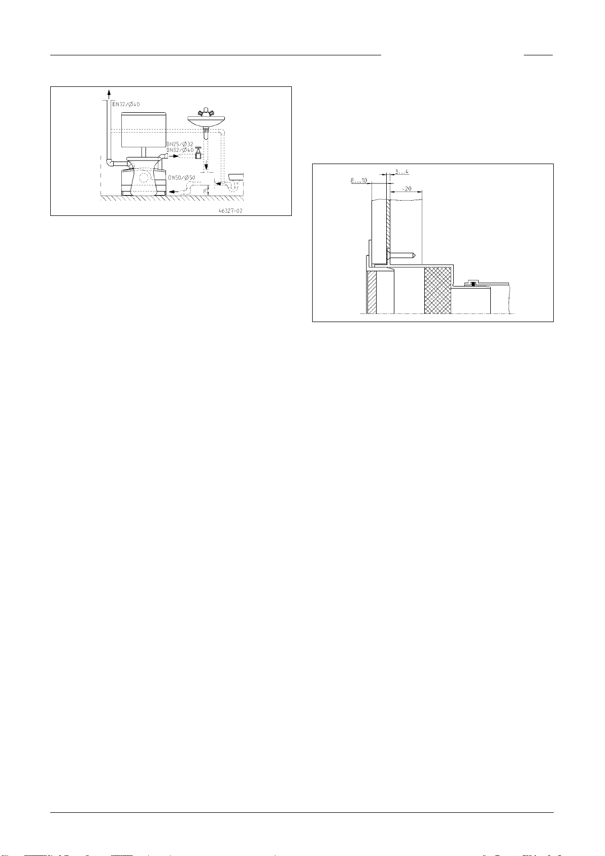
HINWEIS! Aktivkohlelter vermindern Geruchsbelästigungen,
eine Lüftung über Dach vermeidet sie.
Erstellen einer Bohrung ø 76 mm für die Montage der Lüftung.
Querschnitt durch den fertigen Wandaufbau im Bereich des
Einsatzes für Lüftung. Wird die Lüftung über Dach geführt,
werden Einsatz für Lüftung und Aktivkohlelter nicht benötigt.
HINWEIS! Ein Verbindungsrohr zwischen WCFIX und Toilette
führt zu Betriebsstörungen. Dieser Einbauzustand entspricht
nicht der Zulassung des Deutschen Instituts für Bautechnik.
Der Abstand zwischen Ende Anschlussstutzen des WCs und
der Wand muss mindestens 220 mm betragen, damit der Ausbau des WCFIX PLUS möglich ist, ohne die Toilette zu demontieren.
HINWEIS! Die Anschlussleitungen von Dusche und Waschbecken sind möglichst nahe an der Anlage mit einem so genannten Anstaubogen zu versehen. Dieser Bogen muß mindestens
eine Höhe von 75 mm zwischen Rohrsohle und Aufstellebene
haben. Durch Luftpolster in der Anschlussleitung kann es zu
Ablaufproblemen und Rückstau kommen. Um diesen Rückstau
zu vermeiden, ist die Zulaueitung der Dusche in ihrem Hochpunkt zu entlüften. Die Lüftungsleitung kann an die Behälterlüftung angeschlossen werden.
Die mitgelieferte Vorrangklappe muss bei Anschluss einer
Dusche in den entsprechenden Anschlussstutzen eingesetzt
werden.
Wir empfehlen, in die Druckleitung nach der Rückschlagklappe einen Absperrschieber zu installieren. So kann die Rückschlagklappe leichter gewartet werden.
Bei der Installation in einer Vorwand wird der WCFIX PLUS vor
dem Beplanken des Gestelles eingebaut. Dies erleichtert die
Montage und die Überprüfung der Anschlüsse.
Hinweise zur Behälterlüftung
Eine Behälterlüftung ist für die Funktion der Anlage zwingend
erforderlich und muss aus dem Vorwandelement herausgeführt werden. Dies erfolgt z.B. über eine bauseitige HT-Rohrleitung NW 40, die den Einsatz für Lüftung (Lieferumfang)
oder eine Lüftungsleitung über Dach mit der Anlage verbindet. Durch diese Verbindungsleitung ist ausgeschlossen, dass
feuchte Luft aus dem Behälter in den Aufstellraum des WCFIX
PLUS entweicht und dort unbemerkt zu Schimmelbildung und
Feuchtigkeitsschäden führt. Zum Lieferumfang gehört ein Ak-
tivkohlelter, der im Einsatz für Lüftung Geruchsbelästigung
mindert. Vor Einbau ist die Folie zu entfernen. Die Wartung und
der Austausch ist von außen über das Lüftungsgitter vorzunehmen. Der Einsatz für Lüftung kann nach oben, nach vorn
oder zur Seite aus der Vorwand geführt werden, wenn dies gewünscht wird. Er muss jedoch oberhalb aller Entwässerungsgegenstände installiert werden.
Wird der WCFIX PLUS nicht in einer Vorwand installiert, kann
ein Aktivkohlelter direkt am Behälter montiert werden.
Hinweise zu den Modulen für
Vorwandinstallation
Der WCFIX PLUS ist mit allen handelsüblichen Vorwandinstal-
lationssystemen kombinierbar, deren Stelläche eine Tiefe von
18 cm hat.
HINWEIS! Es ist eine Wartungsöffnung mit den Abmessungen
von mindestens 60 x 45 cm vorzusehen. Ein Montage-Kit zur
Integration einer rahmenlosen Wartungsklappe aus Fliesen
kann als Zubehör (JP41075) bestellt werden.
MONTAGE
Prüfen Sie vor Montagebeginn den Lieferumfang der Anlage
und die bauseits zu berücksichtigenden Einbaubedingungen.
Im Einbauraum der Anlage müssen die Zulaueitungen und die
Druckleitung vormontiert werden.
Montieren der Anschlussleitungen
Toilettenanschluss in die gewünschte Zulauföffnung montieren. Hierbei auf korrekten Sitz der Dichtlippe im Behälter achten.
Für die weiteren Zuläufe den Stopfen entfernen und dann DN
50 Steckdichtungen verwenden oder bei Vorwandinstallation
die Anschlussmanschetten mit Schlauchschellen.
HINWEIS! In den Anschlussstutzen für eine Dusche muss die
mitgelieferte Vorrangklappe montiert werden.
Vor Montage die Vorrangklappe im Bereich der Dichtung mit
Vaseline einfetten und in den geöffneten Zulaufstutzen einrasten. Funktion der montierten Klappe prüfen.
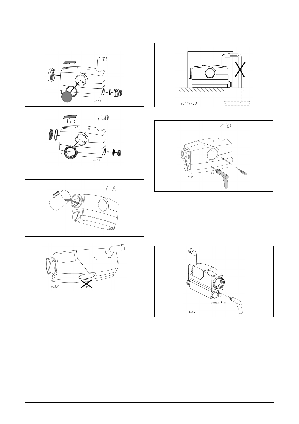
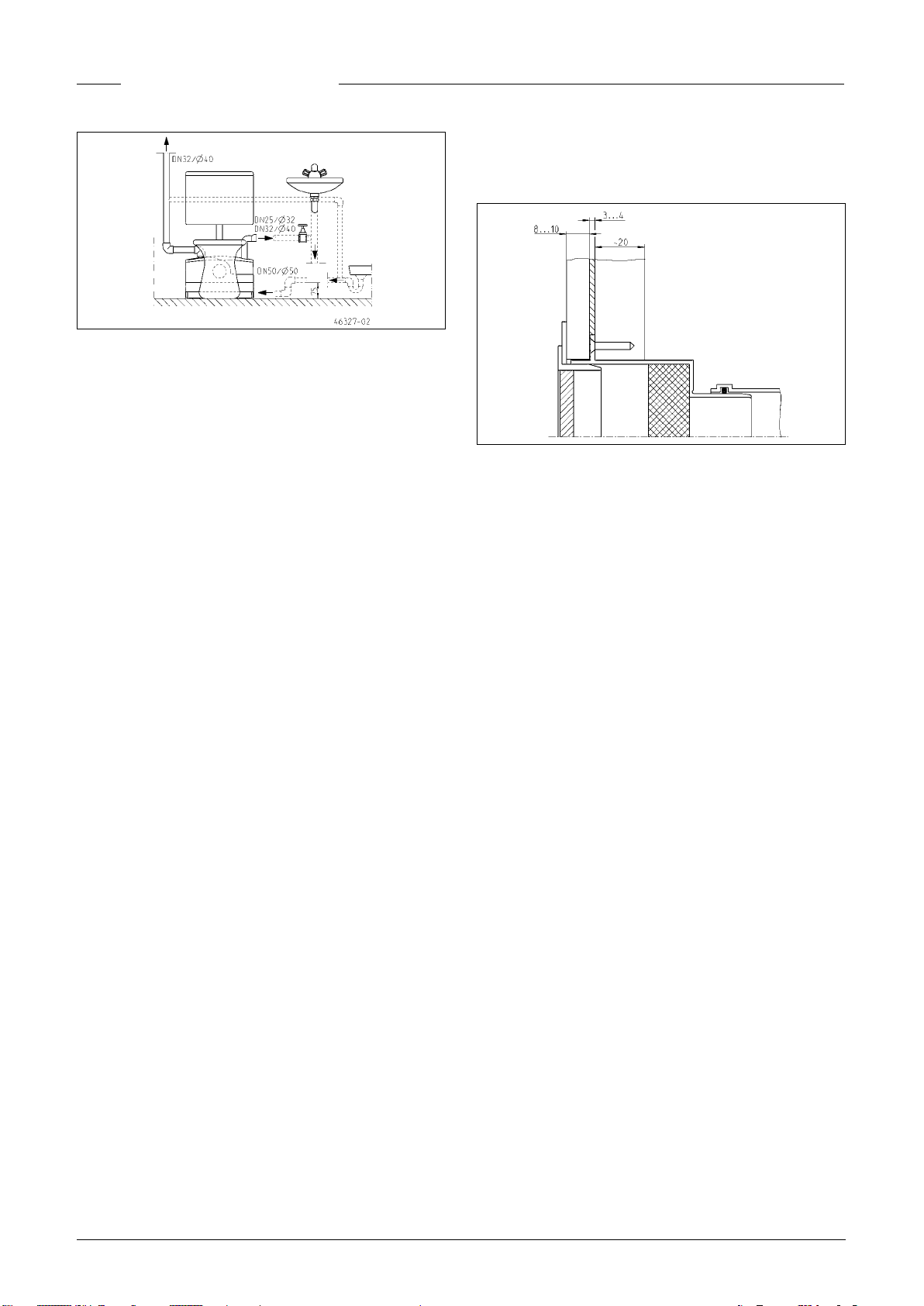
Nicht benötigten Toilettenanschluss
schließen
Den Dichtring in den nicht benötigten Toilettenanschluss setzen, wobei die Dichtlippe im Behälter sitzt. Dann die Dichtung
5
DEUTSCH
einfetten und die Öffnung mit dem Deckel verschließen.
Auftriebsicherung
Dichtheitsprüfung vor dem Einbau
Montieren
WCFIX PLUS mit dem Toilettenanschluss auf den Toilettenstutzen schieben, bei Vorwandinstallation auf das Ablaufrohr.
Hierbei auf einwandfreien Sitz achten.
Zulaueitungen DN50 anschließen, mit Steckdichtungen oder
bei Vorwandinstallation mit Manschetten und Schellen.
Druckleitung mit Abgangskrümmer und Schlauchschellen an-
schließen.
Fäkalienhebeanlagen müssen gegen Auftrieb gesichert wer-
den. Der Aufstell ort darf nicht überutet werden.
Mit einem langen Bohrer, Ø 10 mm, wird ein Loch für den Dübel
gebohrt. Die Stockschraube zur Auftriebsicherung sollte später auf dem Behälter auiegen, bzw. nur geringes Spiel aufweisen. Anschließend den Dübel einsetzen und die Stockschraube
M8, 200 lang, festschrauben.
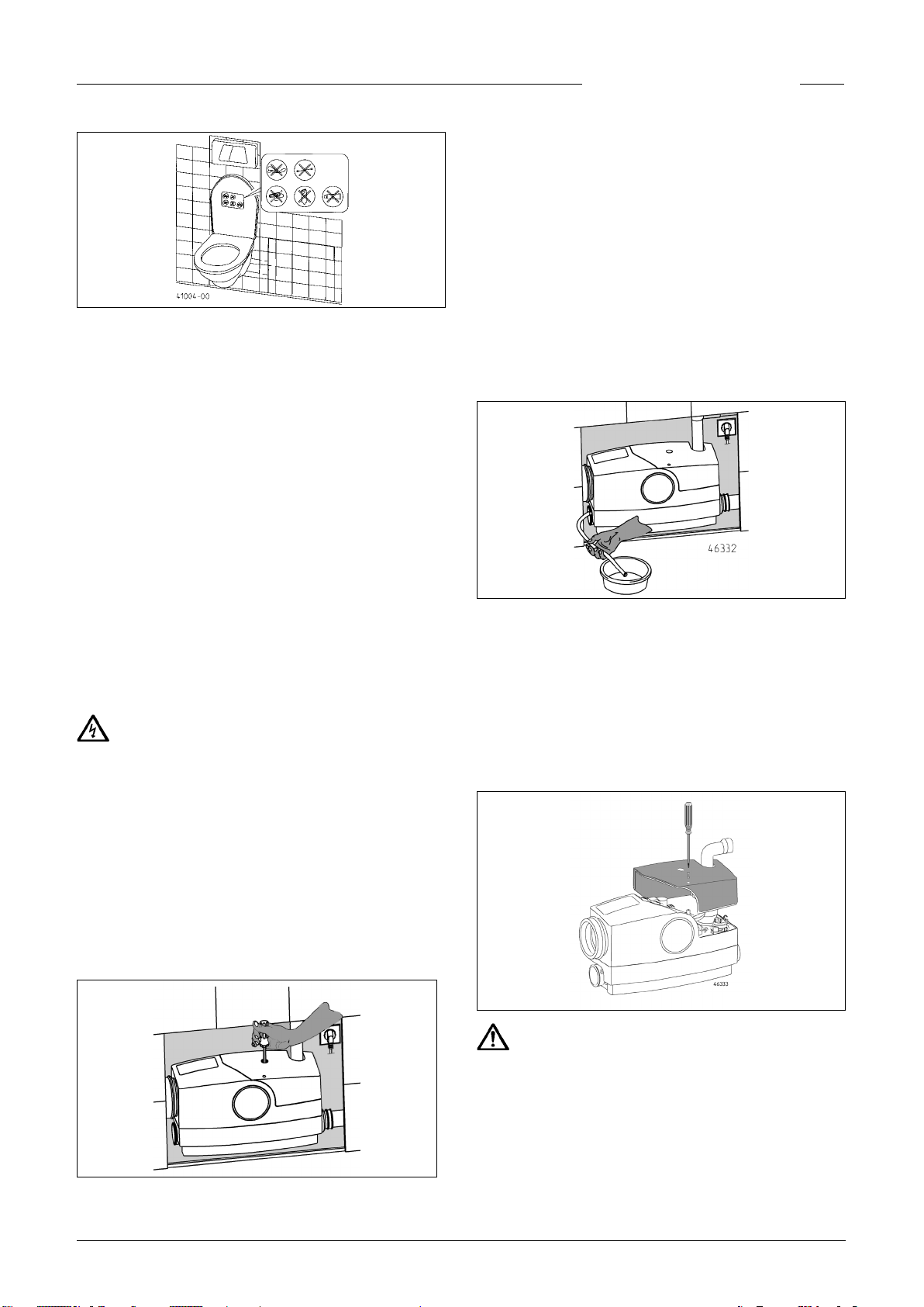
Notentsorgung
Für eine einfache Notentsorgung des angestauten Abwassers
im Behälter kann ein Stück Gartenschlauch am Behälter unten
rechts montiert werden. Dazu muss der Stutzen Ø 13 unten am
Behälter mit einem Spiralbohrer (max. Ø 9) aufgebohrt werden.
Den Schlauch aufschieben und mit einer Schlauchschelle sichern (Anziehdrehmoment 1,5 Nm). Darauf achten, dass die
Ablauföffnung des Schlauches sicher verschlossen ist.
Vor Einbau der Anlage sind die Verbindungsmanschetten DN
50 und DN 100 mit den Schellen (Lieferumfang) auf den Ablaufleitungen zu befestigen. Achten Sie dabei auf korrekten und
dichten Sitz.
HINWEIS! Alle Leitungsverbindungen müssen dicht sein.
6
DEUTSCH
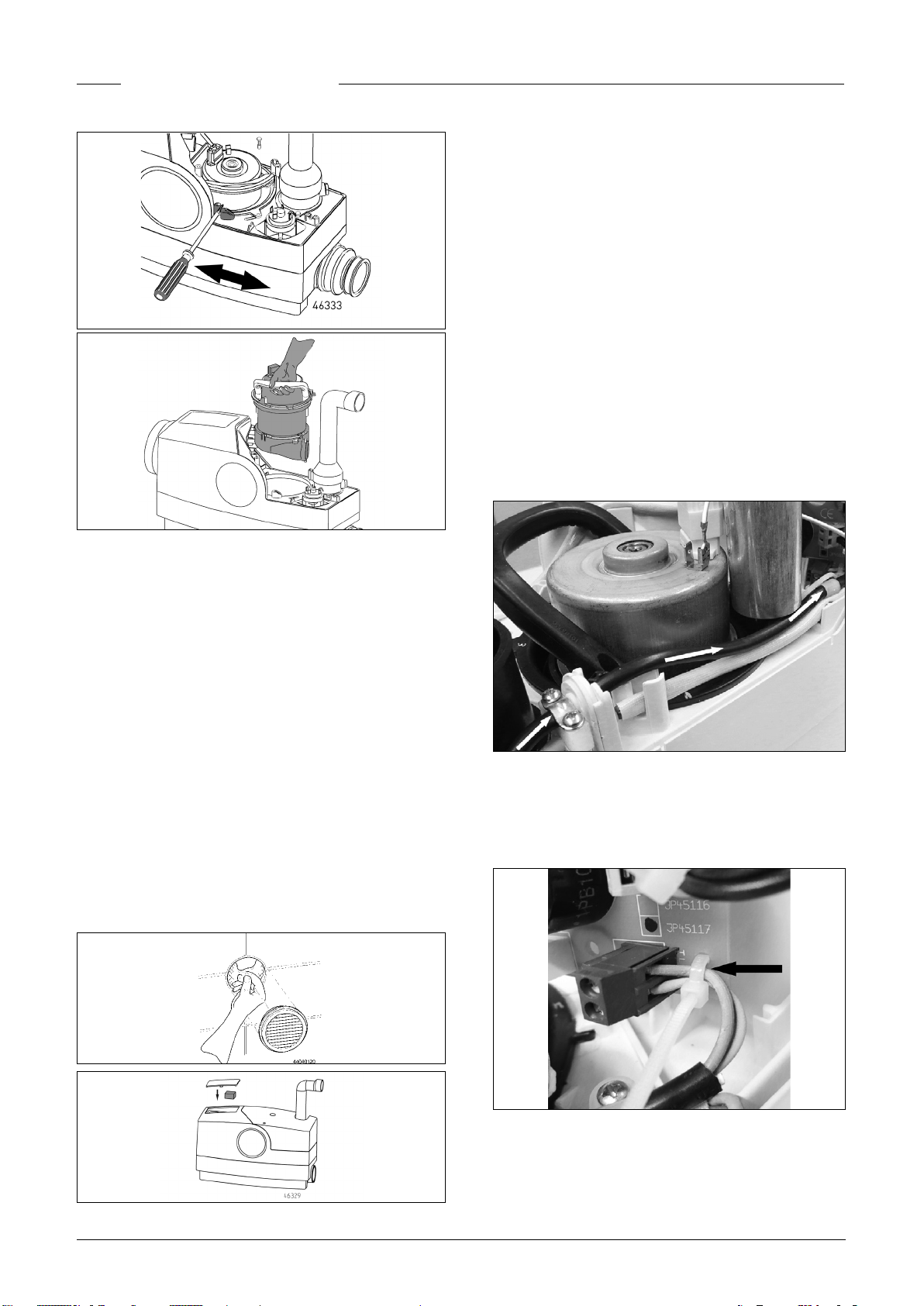
Gang gesetzt werden. Dazu den Stopfen der Bohrung in der
Abdeckhaube entfernen. Einen längeren Schraubendreher
(Torx 30 oder Inbus H5) durch die Bohrung in der Abdeckhaube
stecken. Durch leichte Drehung den Sitz in der Motorwelle ertasten und die Blockierung durch kräftiges Drehen der Welle in
beide Richtungen beseitigen.
Danach zunächst Kontrolle der Pumpe durch kurzzeitiges Einstecken des Netzsteckers.
3. Stellt sich nach Punkt 2 kein normaler Pumpvorgang ein, ist
die Motor-Pumpeneinheit auszubauen.
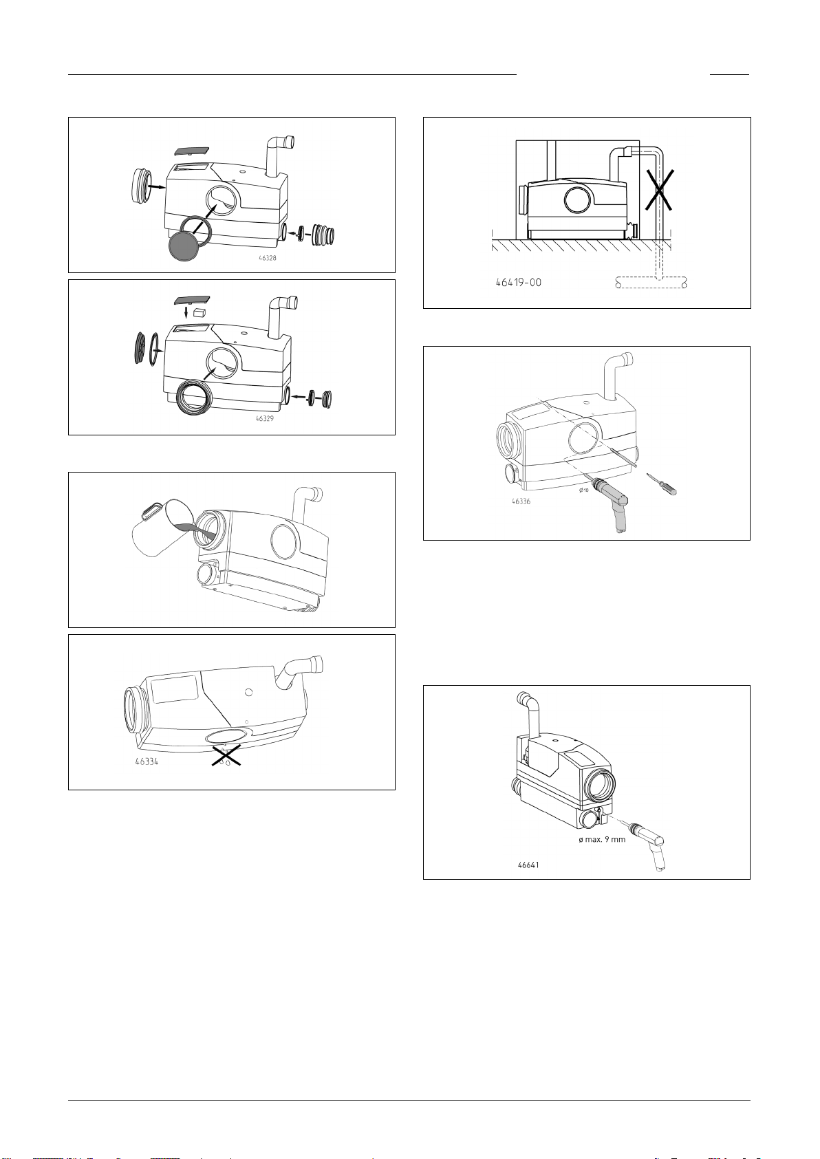
Den im Zubehör bendlichen Aufkleber mit Symboldarstellung
zu Benutzungshinweisen gut sichtbar für die Benutzer der Toilette anbringen, z. B. oberhalb des Toilettendeckels oder auf
der Innenseite des Deckels.
HINWEIS! Unzulässige Einleitungen können zu Funktionsstörungen und Beschädigungen führen, die den Gewährleistungsanspruch aufheben.
Praktische Ratschläge
Nach Verwendung von im Handel erhältlichen Reinigungsmitteln mehrmals spülen, damit keine aggressiven Rückstände
des Reinigers im WCFIX PLUS verbleiben.
Halterungen von Dauerreinigungsmitteln besonders sicher am
WC-Becken befestigen, damit sie nicht in die Anlage gespült
werden können.
Vor der weiteren Demontage muss zunächst der Wasserrückstau im WC-Becken und in der Anlage beseitigt werden. Dazu
können Sie mit einer Bohrmaschine (n>2000 min
und einem ca. 130 mm langen Schraubendrehereinsatz (Tx30
oder H5) eine Notentsorgung vornehmen.
-1
, Linkslauf)
WARTUNG
HINWEIS! Nur eine Elektro-Fachkraft darf an Pumpe oder
Steuerung Elektroarbeiten vornehmen.
WARNUNG!
Vor jeder Arbeit Pumpe und Steuerung vom Netz trennen und
sicherstellen, dass sie von anderen Personen nicht wieder unter Spannung gesetzt werden können.
Der WCFIX PLUS ist bei bestimmungsgemäßem Gebrauch
wartungsarm. Dennoch sollte die Anlage wenigstens jährlich in
Augenschein genommen werden, um die Dichtigkeit aller Anschlüsse zu kontrollieren.
1 x jährlich sollte der Aktivkohlelter der Behälterlüftung ausgetauscht werden.
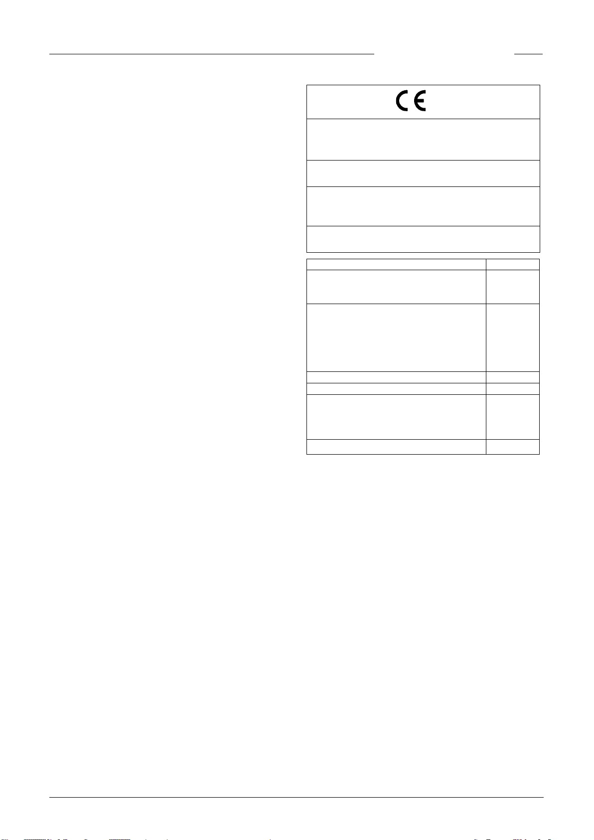
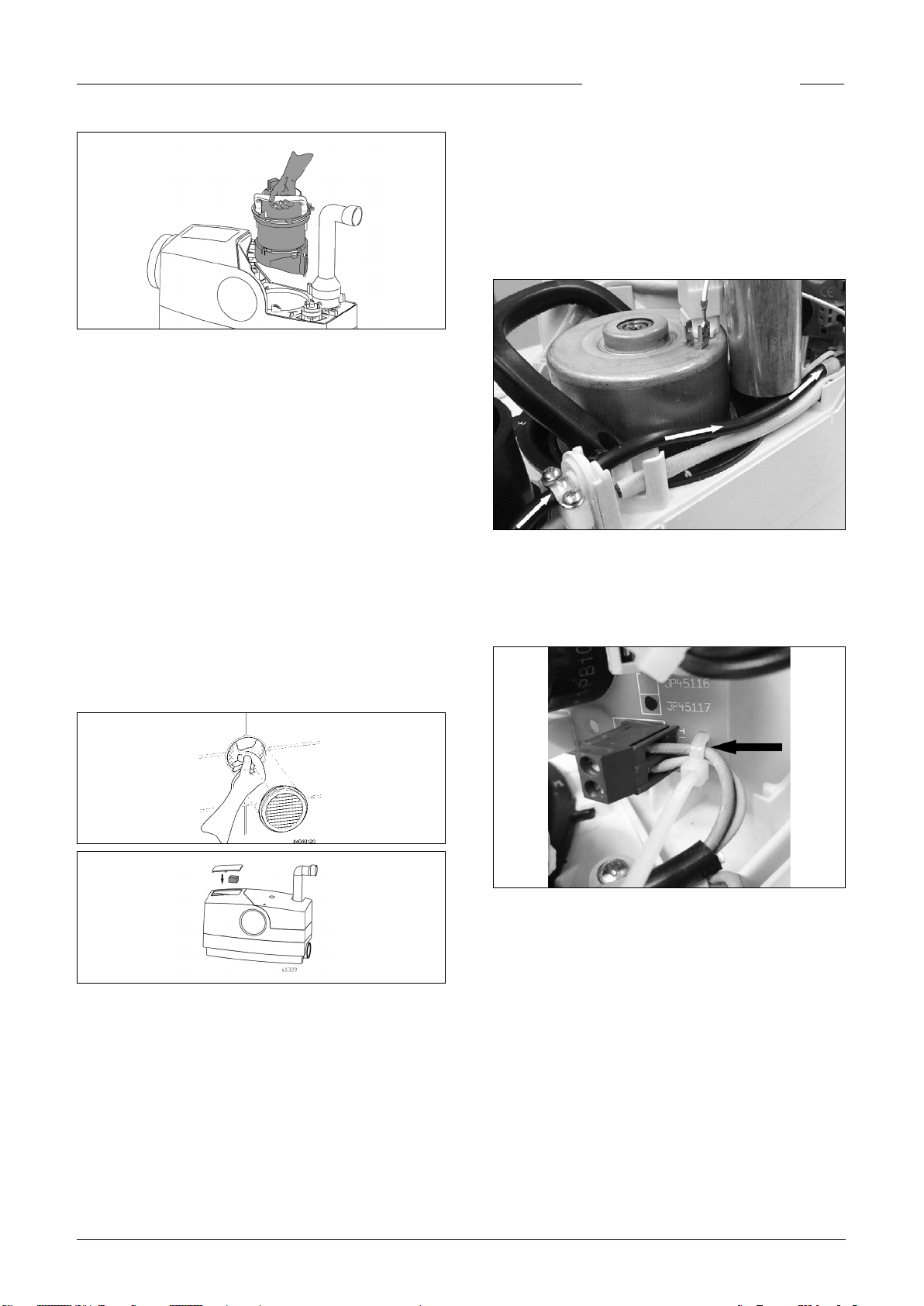
Beseitigung von Verstopfungen bei
Alarmmeldung
1. Wartungsklappe öffnen.
Ist bei der Montage ein Schlauch am Behälter montiert worden,
kann eine einfache Notentsorgung des angestauten Restwassers erfolgen. Dazu wird das Restwasser über den Schlauch in
ein aches Gefäß abgelassen. Anschließend wird der Schlauch
wieder mit einem geeigneten Stopfen verschlossen.
Bei den weiteren Arbeitsgängen bleibt der Behälter installiert.
Nur die Motor-Pumpeneinheit muss ausgebaut werden.
1. Dazu als erstes die Schraube der Abdeckhaube lösen. Die
Haube leicht in Richtung der Druckleitung ziehen bis sich
die Rastung löst. Dann die Haube abnehmen.
VORSICHT!
Die Motoreinheit kann heiß sein.
2. Ist die Pumpe schwergängig oder blockiert, kann sie mit
einem Schraubendreher ohne weitere Demontage wieder in
2. Jetzt Kondensator, Würfelstecker und Erdungskabel vom
Motor lösen und die Schraube der Motoreinheit im Behälter
lösen.
3. Mit einem Schraubendreher die Motorpumpeneinheit lösen,
mit dem Handgriff drehen und aus dem Behälter nehmen.
7
DEUTSCH
Einschaltverzögerung und Nachlaufzeit
werden auf der Platine mit DIP-Schaltern geändert (s. Technische Daten).
Software 5.0: Einschaltverzögerung (S4) und Nachlaufzeit
(S1-S3)
Software 6.08: Einschaltverzögerung (S3-S4) und Nachlaufzeit (S1-S2).
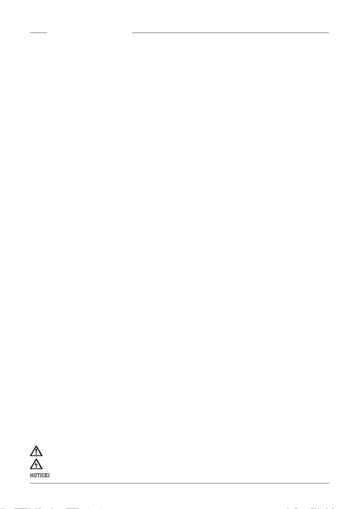
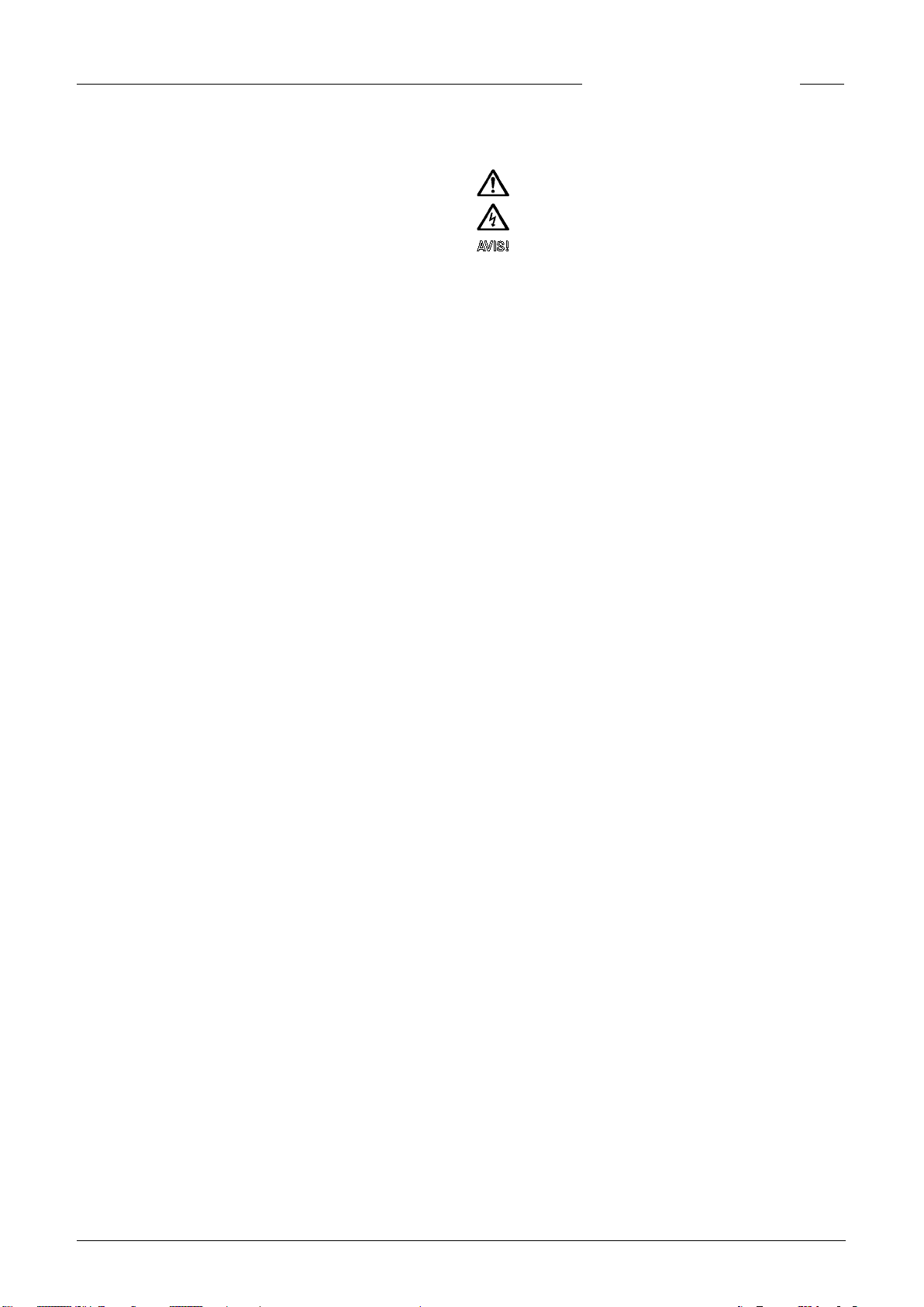
Anschluss der potentialfreien Störmeldung
Zum Anschluss des potentialfreien Schließerkontaktes muss
eine 2-adrige Mantelleitung mit einer Bemessungsspannung
von mindestens 300/500V (z.B. H05.. oder gleichwertig) verwendet werden. Damit die Zugentlastung funktioniert, muss
der Durchmesser der Leitung zwischen 6,5 und 8mm liegen.
– Leitung so kurz wie möglich abmanteln (max. 20mm) und
Adern abisolieren. Bei mehr- bzw. feindrähtigen Adern Aderendhülsen verwenden.
– Mantelleitung parallel und oberhalb der Netzleitung durch
die vor dem Gehäuse liegende Zugentlastungsschelle und
den Steckstutzen in das Gerät führen (siehe Bild).
4. Fremdkörper aus dem Behälter oder der Pumpe durch den
Saugmund entfernen und, falls erforderlich, Bauteile reinigen.
5. Anlage in umgekehrter Reihenfolge wieder sorgfältig montieren.
Hinweis! Vorher die Dichtung der Motor-Pumpeneinheit säubern und mit Vaseline neu einzufetten.
Motor-Pumpeneinheit in den Dichtsitz drücken und durch Drehen entgegen dem Uhrzeigersinn in die Druckleitung kuppeln.
Dann Würfelstecker und Kondensator einstecken und den
Schutzleiter anschließen.
Aktivkohlelter
Der Aktivkohlelter im Zubehörpaket (Lieferumfang) empehlt
sich bei Geruchsbelästigung. Zum Einbau oder Wechsel ist
das Lüftungsgitter/die Lüftungsabdeckung vom Lüftungsgehäuse abzunehmen. Den Filter (zuvor Folie entfernen) in die
Öffnung drücken bzw. entnehmen. Bei verbrauchtem Filter, im
Wartungsfall, neuen Filter verwenden. Anschließend das Lüftungsgitter/die Lüftungsabdeckung wieder aufstecken.
Ein Filterwechsel sollte bei Geruchsbelästigung, mindestens
jedoch 1 mal jährlich erfolgen.
–
– Die Verlegung im Gerät erfolgt ebenfalls parallel zur Netzlei-
tung durch die vor der Platine liegende Kunststoff-Zugentlastungsschelle.
– Die beiden Einzeladern durch den Kabelbinder auf der Pla-
tine zu den Klemmen 40/41 führen – nach Anklemmen der
Adern den Kabelbinder festziehen (siehe Bild).
8
–
DEUTSCH
KLEINE HILFE BEI STÖRUNGEN
0197
WCx läuft nicht an, Wasser bleibt in dem Toilettenbecken
stehen
• Netzspannung prüfen, Sicherung defekt,
• Netzleitung beschädigt. Hinweis! Spezialleitung darf nur
durch unseren Kundendienst oder Elektrofachmann ersetzt
werden.
• Laufrad blockiert, siehe Wartung
Wasser im Toilettenbecken läuft nur sehr langsam ab
• Spülwassermenge im WC-Spülkasten kontrollieren und ggf.
auf 9 l bzw. auf maximale Menge einstellen. Staut das Wasser
nicht höher als normal in das WC-Becken zurück, ein weiteres mal spülen und ggf. wiederholen, sofern noch abgepumpt
wird. Andernfalls bitte den Kundendienst benachrichtigen.
• Förderhöhe zu groß
Mehrfaches Einschalten des WCx nach normalem
Fördervorgang
• Das Ventil im Spülkasten ist undicht und es läuft Wasser
über das WC-Becken in die Anlage.
• Nach dem Pumpvorgang läuft Wasser in den WCx zurück,
weil die Rückschlagklappe undicht oder defekt ist.
• Verstopfung im Behälter vor der Pumpe, so dass Wasser nur
in kleinen Intervallen abgepumpt wird.
Erhöhtes Betriebsgeräusch
• Fremdkörper in der Anlage, siehe Wartung
• Hinweis. Bei jedem 15. Start kommt es zu erhöhter Geräu-
schentwicklung, weil nach der Förderung eine automatische
Kalibrierung der Schaltpunkte stattndet.
JUNG PUMPEN GmbH - Industriestr. 4-6 33803 Steinhagen, Germany
13
451.12.1701
EN 12050-3:2001
Hebeanlage zur begrenzten Verwendung
WCFIX 260 (JP09268/1)
WCFIX PLUS (JP45367)
WCFIX PLUS UK (JP48517)
Automatisches Heben von Abwasser über die Rückstauebene zur be-
grenzten Verwendung
BRANDVERHALTEN NPD
WASSERDICHTHEIT, LUFTDICHTHEIT
- Wasserdichtheit Bestanden
- Geruchsdichtheit Bestanden
WIRKSAMKEIT (HEBEWIRKUNG)
- Förderung von Feststoffen Bestanden
- Rohranschlüsse Bestanden
- Mindestmaße von Lüftungsleitungen Bestanden
- Mindestfließgeschwindigkeit Bestanden
- Freier Mindestdurchgang der Anlage Bestanden
MECHANISCHE FESTIGKEIT Bestanden
GERÄUSCHPEGEL ≤ 70 dB(A)
DAUERHAFTIGKEIT
- der Wasserdichtheit und Luftdichtheit Bestanden
- der Hebewirkung Bestanden
- der mechanischen Festigkeit Bestanden
GEFÄHRLICHE SUBSTANZEN NPD
Alarmmeldung kommt
• Laufzeit zu lang (> 43 sek.), weil Druckleitung oder Pumpen-
saugmund verstopft.
• Zu hoher Wasserstand im WCFIX, weil Pumpe blockiert oder
verstopft ist.
Periodisch auftretende Verstopfung
• Keine Homogenisierung des Mediums = Nachlaufzeit verlän-
gern, bis kurz Schlürfbetrieb hörbar ist.
9
ENGLISH
You have purchased a product made by
pen
and with it, therefore, also excellent quality and service.
Pentair Jung Pum-
Secure this service by carrying out the installation works
in accordance with the instructions, so that our product
can perform its task to your complete satisfaction. Please
remember that damage caused by incorrect installation or
handling will adversely affect the guarantee.
This appliance can be used by children aged 8 years or over
and by persons with limited physical, sensory or intellectual
capabilities, or with limited experience and knowledge, provided that they are supervised or have been instructed in
the safe use of the appliance and are aware of the dangers
involved. Children must not be allowed to play with the appliance. Cleaning and user maintenance must not be carried
out by children unless they are supervised.
Damage prevention in case of failure
Like any other electrical device, this product may fail due to a
lack of mains voltage or a technical defect.
If damage (including consequential damage) can occur as a result of product failure, the following precautions can be taken
at your discretion:
• Installation of a water level dependent (under circumstan-
ces, mains-independent) alarm system, so that the alarm
can be heard before damage occurs.
• Inspection of the collecting tank/chamber for tightness up
to the top edge before – or at the latest, during – installation
or operation of the product.
• Installation of backow protection for drainage units that can
be damaged by wastewater leakage upon product failure.
• Installation of a further product that can compensate in
case of failure of the other product (e.g. duplex unit).
• Installation of an emergency power generator.
As these precautions serve to prevent or minimise consequential damage upon product failure, they are to be strictly
observed as the manufacturer’s guideline – in line with the
standard DIN EN specications as state of the art – when using
the product (Higher Regional Court Frankfurt/Main, Ref.: 2 U
205/11, 06/15/2012).
SAFETY INSTRUCTIONS
This instruction manual contains essential information that
must be observed during installation, operation and servicing. It is therefore important that the installer and the responsible technician/operator read this instruction manual before
the equipment is installed and put into operation. The manual
must always be available at the location where the pump or the
plant is installed.
Failure to observe the safety instructions can lead to the loss
of all indemnity.
In this instruction manual, safety information is distinctly labelled with particular symbols. Disregarding this information
can be dangerous.
General danger to people
Warning of electrical voltage
NOTICE!
Danger to equipment and operation
Qualication and training of personnel
All personnel involved with the operation, servicing, inspection
and installation of the equipment must be suitably qualied
for this work and must have studied the instruction manual in
depth to ensure that they are suciently conversant with its
contents. The supervision, competence and areas of responsibility of the personnel must be precisely regulated by the operator. If the personnel do not have the necessary skills, they
must be instructed and trained accordingly.
Safety-conscious working
The safety instructions in this instruction manual, the existing
national regulations regarding accident prevention, and any
internal working, operating and safety regulations must be adhered to.
Safety instructions for the operator/user
All legal regulations, local directives and safety regulations
must be adhered to.
The possibility of danger due to electrical energy must be prevented.
Leakages of dangerous (e.g. explosive, toxic, hot) substances
must be discharged such that no danger to people or the environment occurs. Legal regulations must be observed.
Safety instructions for installation, inspection and maintenance works
As a basic principle, works may only be carried out to the equipment when it is shut down. Pumps or plant that convey harmful
substances must be decontaminated.
All safety and protection components must be re-tted and/or
made operational immediately after the works have been completed. Their effectiveness must be checked before restarting,
taking into account the current regulations and stipulations.
Unauthorised modications, manufacture of spare parts
The equipment may only be modied or altered in agreement
with the manufacturer. The use of original spare parts and
accessories approved by the manufacturer is important for
safety reasons. The use of other parts can result in liability for
consequential damage being rescinded.
Unauthorised operating methods
The operational safety of the supplied equipment is only guaranteed if the equipment is used for its intended purpose. The
limiting values given in the "Technical Data" section may not be
exceeded under any circumstances.
Instructions regarding accident prevention
Before commencing servicing or maintenance works, cordon
off the working area and check that the lifting gear is in perfect
condition.
Never work alone. Always wear a hard hat, safety glasses and
safety shoes and, if necessary, a suitable safety belt.
Before carrying out welding works or using electrical devices,
check to ensure there is no danger of explosion.
People working in wastewater systems must be vaccinated
against the pathogens that may be found there. For the sake of
your health, be sure to pay meticulous attention to cleanliness
wherever you are working.
Make sure that there are no toxic gases in the working area.
Observe the health and safety at work regulations and make
sure that a rst-aid kit is to hand.
In some cases, the pump and the pumping medium may be hot
and could cause burns.
10
ENGLISH
For installations in areas subject to explosion hazards, special
regulations apply!
APPLICATION
The WCFIX PLUS is used to dispose of sewage from a directly
connected toilet, even if this lies below the local backow level.
• The number of people using the toilet should be small, and
an additional toilet, installed above the backow level, must
be available for them to use.
• Only domestic wastewater, without any harmful substances
as dened in EN 12056, may be disposed of.
• The unit operates in combination with a with cistern that
supplies a ush volume of at least six litres. Proper operation cannot be guaranteed if the ush volume is less than
six litres. This may be the case if an economy ush button is
used, for example.
• A maximum of one wash basin, one shower and one bidet
can be connected in addition to the toilet. All of the xtures
must be installed in the same room as the WCFIX PLUS. If no
additional units are to be served, a ush volume of 9 litres is
recommended for the toilet.
• In accordance with EN 12050-3, the connection of other
appliances, such as washing machines, kitchen sinks, dishwashers or bathtubs, is not permitted.
When installed correctly and used for its intended purpose, the
unit meets all the protection requirements of EMC Directive
2014/30/EU and is suitable for domestic use and for connection to the public power supply network.
It is ideal for use in renovation or conversion works in domestic
situations where the installation of a toilet would be desirable.
The unit pumps the sewage and toilet paper from the toilet into
an existing foul water drainage pipe. When installed below the
backow level, the unit also provides backow protection. This
requires the installation of a vertical backow prevention loop
in the pressure pipe.
NOTICE!
• The unit must never be used for the disposal of hygiene ar-
ticles, paper towels, moist toilet tissues, left-over food, solvents, chemicals, grease etc.
• The ow velocity in the pressure pipe must be at least 0.7
m/s.
• The operating limit with regard to manometric head is 0.6
bar (6.0 m head).
Permissible temperature of the pumped uid: 35°C, operating
mode: intermittent operation S3, 30% (3 minutes operation – 7
minutes rest)
When installing the system in bathrooms or shower rooms,
German VDE regulation 0100 Part 701 must be observed.
The WCFIX PLUS is frost resistant down to a temperature of
–20 °C when stored in dry conditions. Once the unit is installed,
however, the residual water in the system must not be allowed
to freeze.
The pump must only be connected to sockets that have been
installed properly in accordance with the regulations and are
protected with at least 10 A (slow) and RCD-safety switches
(30mA).
NOTICE! Only qualied electricians may carry out electrical
works to the pump, connector plugs or controls.
NOTICE! Never put the mains plug into water! If water gets into
the plug, this can cause malfunctions or damage.
The relevant standards (such as EN standards), country-spe-
cic regulations (such as VDE in Germany), and the regulations
of the local power supply companies must be observed.
Observe the operating voltage (see the type plate)!
No additional motor protection is required, since the system
has an integrated coil thermostat.
Unacceptably high temperatures and long periods of continu-
ous operation cause the thermostat to shut down the motor.
The pump is switched on again automatically after cooling
down - risk of injury!
For this reason, always disconnect the device from the mains
before remedying the fault! In order to do this, unplug from the
mains supply.
System controls
The WCFIX PLUS has a level controller that switches the pump
on and off depending on the level of the water.
The start-up delay and shut-off delay are set via DIP switches
on the control circuit board.
The mains-dependent alarm sounds to indicate a malfunction
if the pumping operation continues for longer than 43 seconds.
A potential-free fault indicator contact (5 A/250 V) on the circuit board can be used to relay the alarm.
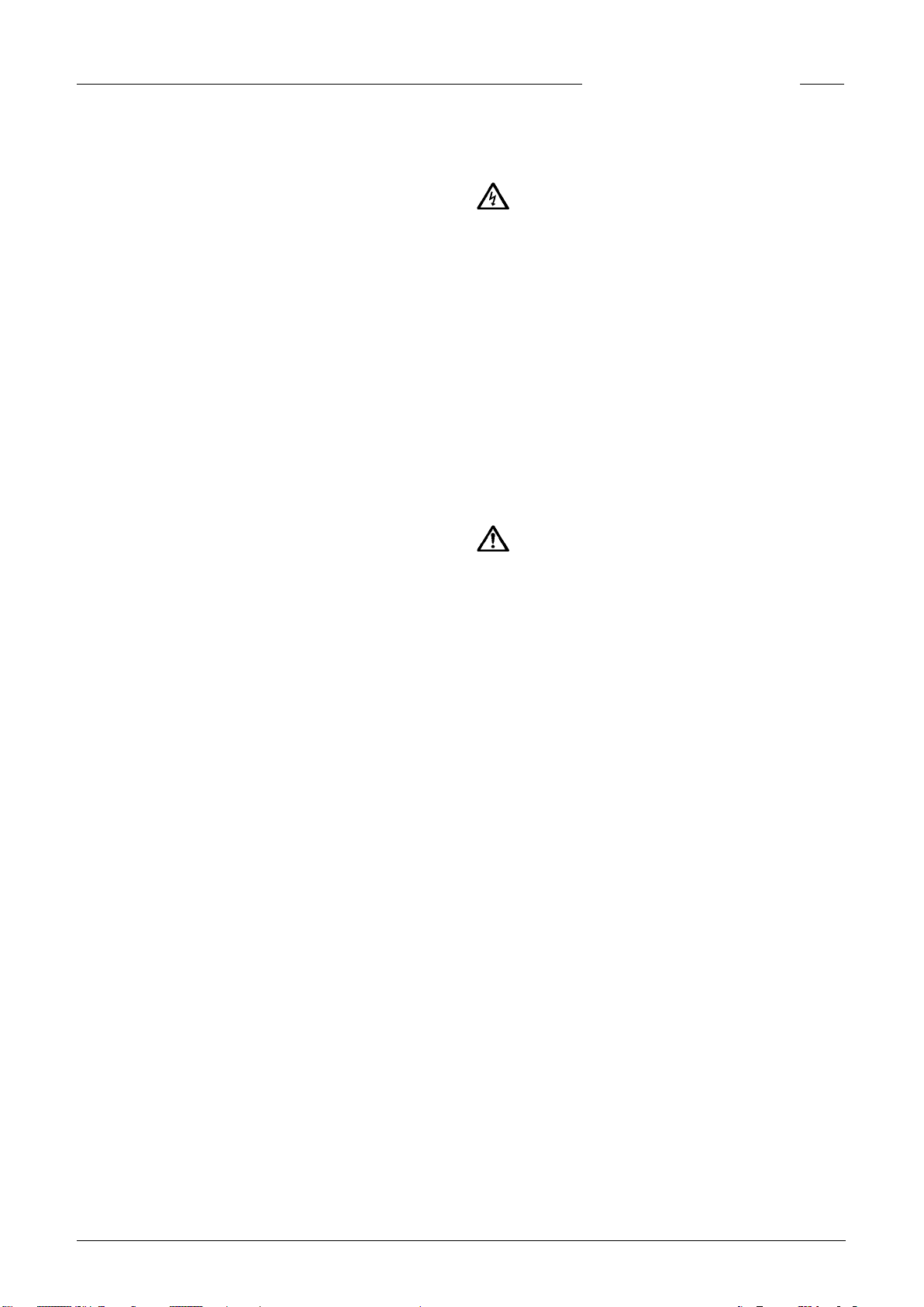
For front-wall installations
If the toilet is wall-mounted, the WCFIX PLUS is installed immediately adjacent to the toilet module. The unit is connected
to the outlet bend of the front-wall installation via a 15º bend
with a nominal diameter (DN) of 100 mm and high temperature
resistance (HT). The WCFIX PLUS can be installed to the left or
right of the toilet.
For free-standing toilets
The WCFIX PLUS is tted directly to standard toilets (complying with DIN 1387 or 1388) with a horizontal outlet. The vertical
distance between the mounting surface and the centre of the
outlet branch must be at least 180 mm.
ELECTRICAL CONNECTION
WARNING!
CAUTION!
INSTALLATION
11
ENGLISH
NOTICE! If a connecting pipe is tted between the WCFIX and
the toilet, this will result in malfunctions. This method of installation does not comply with the approval of the Deutsches
Institut für Bautechnik (the German approval body for construction products and types of construction).
The distance between the wall and the end of the connection
branch of the toilet must be at least 220 mm if the WCFIX PLUS
is to be installed without moving the toilet.
NOTICE! The connection pipes from the shower and washba-
sin must be tted with a so-called back-up bend, installed as
close to the unit as possible. The pipe invert of this bend must
be at a height of at least 75 mm above the mounting surface on
which the unit is xed. Air pockets in the connecting pipe can
cause run-off problems and the water could back up. To prevent back-ups, the inlet pipe from the shower must be vented
at its highest point. The ventilation pipe can be connected into
the tank ventilation.
When installing a shower, the priority valve supplied with the
unit must be inserted into the corresponding connection port.
NOTICE! We recommend installing a shut-off valve after the
check valve in the pressure pipe. This allows the check valve
to be serviced easily.
In the case of front-wall installations, the WCFIX PLUS should
be installed before the panelling is xed to the frame. This
makes it easier to install the unit and to check the connections.
Instructions regarding ventilation of the tank
The tank ventilation is essential for proper operation of the
system and must be fed out through the front-wall panel. A
pipe with a nominal diameter of 40 mm and high temperature
resistance (not supplied) can be used to connect the system to
the ventilation insert (supplied) or to a roof vent. This connection pipe ensures that no damp air can escape from the tank
into the room in which the WCFIX PLUS is installed, where it
could otherwise cause hidden moisture-related damage or
mould growth. An activated carbon lter is supplied with the
unit to minimise unpleasant odours. The protective lm must
be removed before use. The lter can be replaced and serviced
from outside via the ventilation grille. The ventilation insert
can be xed into the front wall at the top, the side or the front
of the wall, if required. However, it must be installed above the
height of all of the xtures that are connected to the WCFIX
PLUS.
If the WCFIX PLUS is not installed behind a front wall, an acti-
vated carbon lter can be tted at the tank.
NOTICE! Activated carbon lters reduce unpleasant odours,
whereas a roof vent prevents them.
A hole 76 mm in diameter must be drilled for the installation of
the ventilation system.
Cross-section through the nished wall where the ventilation
insert is installed. If the system is ventilated via a roof vent,
then the ventilation insert and activated carbon lter are not
required.
Instructions regarding the modules for frontwall installation
The WCFIX PLUS is compatible with all commercially available
front-wall installation systems that have a footprint depth of at
least 18 cm.
NOTICE! A maintenance hatch opening measuring at least 60
x 45 cm must be created. An installation kit for integrating a
frameless, tiled maintenance hatch cover can be ordered separately, as an accessory (JP41075).
MOUNTING
Before commencing work, check the contents of the package
and the conditions that need to be taken into account at the
installation site. The inlet pipes and the pressure pipe must
be installed in advance in the room where the unit is to be installed.
Fitting the connection pipes
Fit the toilet connector into the desired inlet opening. Make
sure that the sealing lip is tted properly in the tank.
For the other inlets, remove the stopper and then use DN 50
plug-in seals or, in the case of front-wall installations, use the
connection sleeves with hose clips.
NOTICE! When installing a shower, the priority valve supplied
with the unit must be inserted into the corresponding connection port.
Before tting the priority valve, lubricate the seal area with
petroleum jelly. Then insert the valve into the open inlet port,
making sure that it locks properly into place. Check that the
valve ap works properly.
Seal the unused toilet inlet port
Insert the sealing ring into the unused toilet inlet port, making
sure that that the sealing lip is tted properly in the tank. Then
grease the seal and close the opening by tting the cover.
12
ENGLISH
Buoyancy prevention
Leakage test prior to installation
Installation
Push the WCFIX PLUS with the toilet connector onto the toilet
connection branch or, in the case of front-wall installations,
onto the outlet pipe. Make sure that the connections are tted
properly.
Connect the DN 50 inlet pipes using plug-in seals or, in the
case of front-wall installations, with sleeves and clips.
Connect the pressure pipe with the pressure port discharge
elbow and hose clips.
Sewage lifting units must be protected against buoyancy. The
installation site should never be ooded.
A hole must be drilled for the wall plug, using a long drill with a
diameter of 10 mm. The anti-buoyancy hanger bolt should later
lie on the tank or have just a small amount of play. Insert the
wall plug and screw the M8, 200-mm-long hanger bolt tightly
into place.
Emergency disposal
To drain the tank in an emergency, a section of garden hosepipe be connected to the tank at the bottom on the right-hand
side. First, you will have to open up the 13-mm-diameter port
by drilling through it with a spiral drill (maximum diameter:
9 mm). Push the hosepipe onto the port and secure it with a
hose clip (tightening torque: 1.5 Nm). Make sure that the outlet
opening of the hosepipe is securely sealed.
Before installing the unit, fasten the DN 50 and DN 100 connecting sleeves to the discharge pipes using the clips (sup-
plied). Make sure that they are properly tted and do not leak.
NOTICE! All of the pipe connections must be properly sealed
and free of leaks.
13
ENGLISH
The sticker that is supplied with the unit and shows symbols
giving instructions for use must be attached where it can be
clearly seen by people using the toilet: for example above the
toilet lid or on the inside of the lid.
Notice! Putting prohibited materials into the toilet can cause
malfunctions, damage the unit and invalidate the warranty.
Practical tips
After using commercially available cleaning agents, ush the
toilet several times to ensure that no aggressive cleaning
agent residues are left in the WCFIX PLUS.
Toilet rim blocks must be fastened particularly securely to the
toilet bowl rim so that they cannot be ushed into the unit.
SERVICING
NOTICE! Only qualied electricians may carry out electrical
works to the pump or the controls.
to check that the pump now works properly.
3. If the unit still does not pump normally after completing step
2, then the motor/pump unit must be removed.
Before dismantling the unit, any water that is backed up in the
toilet bowl and in the unit must be drained off. The emergency
draining procedure can be carried out using an electric drill (n
> 2000 RPM anticlockwise) and a 130-mm-long screwdriver bit.
If a hose was xed to the tank during installation, then the water in the system can be drained away quite simply through the
hose and into a shallow container. The hose must then be resealed using a suitable stopper.
The tank remains installed during the next steps. Only the motor/pump unit needs to be removed.
1. To do this, rst unfasten the screw on the cover. Slide the
cover gently towards the pressure pipe until it comes free.
Then remove the cover.
WARNING!
Before carrying out any works: disconnect the pump and the
controls from the mains and take steps to ensure that no one
else can reconnect them to the power supply.
When used properly, the WCFIX PLUS requires little maintenance. The unit should be checked at least once a year, however, to ensure that all of the connections are still watertight.
The activated carbon lter should be changed once a year.
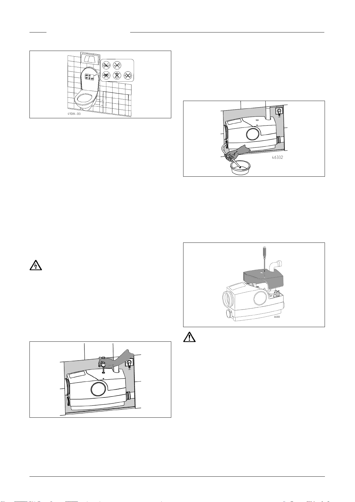
Clearing blockages after an alarm
1. Open the maintenance hatch.
2. If the pump is sluggish or blocked, it can be set in motion
again using a screwdriver, without any further disassembly. To
do this, remove the stopper from the hole in the cover. Insert a
long screwdriver (Torx 30 or grub-screw H5) through the hole in
the cover. Turn the screwdriver gently until it engages with the
slot in the motor shaft and then turn the shaft forcefully in both
directions to clear the blockage.
Then connect the mains plug to the power supply temporarily,
CAUTION!
The motor unit may be hot.
2. Now disconnect the condenser, connector plug and earth
cable from the motor and unfasten the screw of the motor
unit in the tank.
3. Loosen the motor/pump unit with a screwdriver, then grip
the handle and turn the unit before lifting it out of the tank.
14
ENGLISH
ble must lie between 6.5 and 8.0 mm.
– Strip only a short section of the cable (freeing a length of no
more than 20 mm) and strip the leads. If the leads are ne or
stranded, then use end sleeves.
– Keeping the sheathed cable above and parallel to the mains
cable, feed the sheathed cable through the strain-relief
clamp in front of the housing and then through the entry
sleeve and into the unit (see image).
4. Remove any foreign matter from the tank and the pump
through the suction opening and clean the components if necessary.
5. Carefully reassemble the parts in reverse order.
Notice! Before reassembly, the seal of the motor/pump unit
must be cleaned and greased with petroleum jelly.
Press the motor/pump unit into the seal seat and couple it with
the pressure pipe by turning anticlockwise. Then attach the
connector plug and condenser and connect the earth cable.
Activated carbon lter
The installation of the activated carbon lter (in the accessory
packet included in the scope of delivery) is recommended if
unpleasant odours are present. To install or change the lter,
remove the ventilation grille/cover from the ventilation hous-
ing. Take out the old lter and insert the new lter (after removing the protective lm) into the opening. When servicing
the unit or when the lter is saturated, replace the lter with a
new one. Then replace the ventilation grille/cover.
If unpleasant odours are an issue, the lter should be replaced
at least once a year.
–
– Inside the unit, the cable is also laid parallel to the mains
cable and through the plastic strain-relief clamp that lies in
front of the circuit board.
– Feed the two leads through the cable tie on the circuit board
to terminals 40/41. Once they have been connected to the
terminals, tighten the cable tie (see image).
Shut-off delay and start-up delay
These delay times are adjusted via DIP switches on the circuit
board (s. Technical Data).
Software 5.0: Shut-off delay (S1-S3) and start-up delay (S4)
Software 6.08: Shut-off delay (S1-S2) and start-up delay (S3-
S4)
Connecting the potential-free fault alarm
A 2-lead sheathed cable with a rated voltage of at least
300/500 V (e.g. H05... or equivalent) must be used to connect
to the potential-free normally open contact. To ensure that the
strain-relief clamp functions properly, the diameter of the ca-
–
QUICK TIPS FOR REMEDYING
FAULTS
WCFIX will not start up and water remains in
the toilet bowl
• Check the mains voltage, fuse is defective
• mains cable is damaged. Notice! The special cable may be
replaced only by our customer service or a qualied electrician.
• Impeller is blocked, see servicing instructions.
Water drains only very slowly from the toilet
bowl
• Check the amount of ushing water available in the toilet
cistern and set it to nine litres or to the maximum quantity
15

ENGLISH
if necessary. If more water than usual remains in the toilet
bowl, ush again and repeat, if necessary, provided that the
water continues to be pumped out. If this does not help, then
please call customer service.
• Discharge head is too large.
WCFIX switches on repeatedly after normal
pumping cycle
• Cistern valve is leaking and water ows constantly through
the toilet bowl and into the unit.
• After the pump stops, water runs back into the WCFIX be-
cause the non-return valve is leaking or defective.
• Obstruction in the tank upstream of the pump, resulting in
water only being pumped away at short intervals.
0197
JUNG PUMPEN GmbH - Industriestr. 4-6 33803 Steinhagen, Germany
13
451.12.1701
EN 12050-3:2001
Lifting plant for limited applications
WCFIX 260 (JP09268/1)
WCFIX PLUS (JP45367)
WCFIX PLUS UK (JP48517)
Automatic lifting of wastewater above the backflow level, for limited
applications.
Noisy operation
• Foreign matter in the unit. Follow servicing instructions.
• Note. Due to the fact that the switching points are automati-
cally calibrated after operation, a louder noise is heard after
every 15th start-up.
Alarm signal sounds
• Running time too long (> 43 seconds), because the pressure
pipe or pump suction opening is blocked.
• Water level in the WCFIX is too high, because the pump is
obstructed or blocked.
Periodic blocking
• No homogenisation of the waste matter = extend the shut-
off delay time until sipping mode can be heard.
REACTION TO FIRE NPD
WATERTIGHTNESS, AIRTIGHTNESS
- Water tightness Pass
- Odour tightness Pass
EFFECTIVENESS (LIFTING EFFECTIVENESS)
- Pumping of solids Pass
- Pipe connections Pass
- Minimum dimensions of ventilating pipes system Pass
- Minimum flow velocity Pass
- Minimum free passage of the plant Pass
MECHANICAL RESISTANCE Pass
NOISE LEVEL ≤ 70 dB(A)
DURABILITY
- of structural stability Pass
- of lifting effectiveness Pass
- of mechanical resistance Pass
DANGEROUS SUBSTANCES NPD
16
FRANÇAIS
Vous avez opté pour un produit Pentair Jung Pumpen, synonyme de qualité et de performance. Assurez-vous cette
performance par une installation conforme aux directives:
notre produit pourra ainsi remplir sa mission à votre entière
satisfaction. N‘oubliez pas que les dommages consécutifs à
un maniement non conforme porteront préjudice au droit à
la garantie.
Cet appareil peut être utilisé par des enfants d'au moins 8
ans ainsi que par les personnes ayant des capacités physiques, sensorielles ou mentales limitées ou qui manquent
d'expérience et de connaissance, dans la mesure où ils sont
surveillés ou s'ils ont reçu des instructions pour une utilisation en toute sécurité de l'appareil et qu'ils comprennent les
risques qui en résultent. Les enfants ne doivent pas jouer
avec l'appareil. Le nettoyage et l'entretien de l'appareil ne
doivent pas être effectués par des enfants si ceux-ci ne
sont pas sous surveillance.
Prévention des dommages en cas de défaillance
Comme tout autre appareil électrique, ce produit peut aussi
tomber en panne suite à une absence de tension ou à un défaut technique.
Si un dommage (également dommage consécutif) se produit
en raison de la défaillance du produit, les dispositions suivantes doivent être prise en particulier selon votre appréciation :
• Montage d’une alarme en fonction du niveau d’eau (éventuel-
lement aussi indépendante du réseau électrique) de sorte
que l’alarme puisse être perçue avant l’apparition d’un dommage.
• Contrôle de l’étanchéité du réservoir collecteur / cuve utili-
sée jusqu’au bord supérieur avant - toutefois au plus tard- le
montage ou la mise en service du produit.
• Montage de protection anti-retour pour les objets de drai-
nage sur lesquels un dommage peut survenir par l’écoulement d’eau usée après une défaillance du produit.
• Montage d’un autre produit pouvant compenser la défail-
lance du produit (par ex. poste double).
• Montage d’un groupe de secours.
Étant donné que ces dispositions servent à prévenir ou réduire
les dommages consécutifs à une défaillance du produit, elles
sont obligatoires en tant que disposition du fabricant au même
titre que les contraintes normatives de la FR EN comme état
de la technique lors de l’utilisation du produit (OLG Francfort/
Main, n°dossier: 2 U 205/11, 15.06.2012).
CONSIGNES DE SÉCURITÉ
Ces instructions de service contiennent des informations essentielles à respecter lors de l‘installation, de la mise en service et de la maintenance.
Il est impératif que le monteur et l‘exploitant/ le personnel qualié concernés lisent les instructions de service avant le montage et la mise en service.
Les instructions doivent toujours être disponibles sur le lieu
d‘utilisation de la pompe ou de l‘installation.
Le non respect des consignes de sécurité peut entraîner la
perte de tous les droits à réparation du dommage.
Dans ces instructions de service, les consignes de sécurité
sont identiées de manière particulière par des symboles.
Risque d‘ordre général pour les personnes
Avertissement contre la tension électrique
AVIS! Danger pour la machine et le fonctionnement
Qualication du personnel
Le personnel pour le maniement, la maintenance, l‘inspection
et le montage doit posséder la qualication nécessaire à ce
type de travaux et il doit s‘être susamment bien informé par
une étude approfondie des instructions de service.
Domaine de responsabilité, l‘exploitant doit régler avec préci-
sion la compétence et le contrôle du personnel.
Si le personnel ne possède pas les connaissances nécessaires,
il est impératif de le former et de l‘instruire.
Travailler en étant soucieux de la sécurité
Il est impératif de respecter les consignes de sécurité, les règlements nationaux en vigueur concernant la prévention des
accidents et les prescriptions internes éventuelles de travail,
de service et de sécurité contenus dans ces instructions.
Consignes de sécurité pour l‘exploitant/ l‘utilisateur
Les directives légales, les règlements locaux et les directives
de sécurité doivent être respectés.
Il faut exclure les risques dus à l‘énergie électrique.
Les fuites de matières dangereuses à refouler (explosives,
toxiques ou brûlantes par exemple) doivent être évacuées de
telle sorte qu‘elles ne représentent aucun danger pour les personnes et l‘environnement. Les directives légales en vigueur
sont à respecter.
Consignes de sécurité pour le montage, les travaux d‘inspection et de maintenance
D‘une manière générale, les travaux à effectuer devront l‘être
exclusivement sur une machine à l‘arrêt. Les pompes ou agrégats refoulant des matières dangereuses pour la santé doivent
être décontaminés.
Directement après la n des travaux, tous les dispositifs de sécurité et de protection doivent être remis en place ou en ser-
vice. Leur ecacité est à contrôler avant la remise en service
et en tenant compte des directives et règlements en vigueur.
Transformation et fabrication de pièces détachées sans
concertation préalable
Une transformation ou une modication de la machine est
uniquement autorisée après consultation du fabricant. Les
pièces détachées d‘origine et les accessoires autorisés par
le fabricant servent à la sécurité. L‘utilisation d‘autres pièces
peut annuler la responsabilité quant aux conséquences en résultant.
Formes de service interdites
La sécurité d‘exploitation de la machine livrée est uniquement
garantie lors d‘une utilisation conforme. Il est absolument interdit de dépasser les valeurs limites indiquées au chapitre «
Caractéristiques technique «.
Consignes concernant la prévention des accidents
Avant les travaux de montage ou de maintenance, barrer la
zone de travail et contrôler le parfait état de l‘engin de levage.
Ne jamais travailler seul et utiliser un casque, des lunettes
protectrices et des chaussures de sécurité, ainsi qu‘en cas de
17
 Loading...