

Pentair Jung Pumpen US 73 E, Ex, Jung Pumpen US EX Series, Jung Pumpen US 103 D, Jung Pumpen US 73 D Instruction Manual
...
US EX
US 73 E, Ex US 73 D, Ex US 103 E, Ex US 103 D, Ex
DE Original-
Betriebsanleitung
JUNG-PUMPEN.DE B 25268-63-1912
EN Instruction Manual
FR
Instructions de service
NL Gebruikshandleiding
IT Istruzioni per l‘uso
PL Instrukcja eksploatacji

2

DEUTSCH
Sie haben ein Produkt von Pentair Jung Pumpen gekauft
und damit Qualität und Leistung erworben. Sichern Sie sich
diese Leistung durch vorschriftsmäßige Installation, damit
unser Produkt seine Aufgabe zu Ihrer vollen Zufriedenheit
erfüllen kann. Denken Sie daran, dass Schäden infolge unsachgemäßer Behandlung die Gewährleistung beeinträchtigen. Beachten Sie deshalb die Hinweise der Betriebsanleitung!
Dieses Gerät kann von Kindern ab 8 Jahren und darüber
sowie von Personen mit verringerten physischen, sensorischen oder mentalen Fähigkeiten oder Mangel an Erfahrung
und Wissen benutzt werden, wenn sie beaufsichtigt oder
bezüglich des sicheren Gebrauchs des Gerätes unterwiesen
wurden und die daraus resultierenden Gefahren verstehen.
Kinder dürfen nicht mit dem Gerät spielen. Reinigung und
Benutzer-Wartung dürfen nicht von Kindern ohne Beaufsichtigung durchgeführt werden.
Schadensvermeidung bei Ausfall
Wie jedes andere Elektrogerät kann auch dieses Produkt
durch fehlende Netzspannung oder einen technischen Defekt
ausfallen.
Wenn Ihnen durch den Ausfall des Produktes ein Schaden
(auch Folgeschaden) entstehen kann, sind von Ihnen insbesondere folgende Vorkehrungen nach Ihrem Ermessen zu treffen:
• Einbau einer wasserstandsabhängigen (unter Umständen
auch netzunabhängigen) Alarmanlage, so dass der Alarm vor
Eintritt eines Schadens wahrgenommen werden kann.
• Prüfung des verwendeten Sammelbehälters / Schachtes auf
Dichtig keit bis Oberkante vor Inbetriebnahme des Produktes.
• Einbau von Rückstausicherungen für diejenigen Entwässe-
rungsgegenstände, bei denen durch Abwasseraustritt nach
Ausfall des Produktes ein Schaden entstehen kann.
• Einbau eines weiteren Produktes, das den Ausfall des Pro-
duktes kompensieren kann (z.B. Doppelanlage).
• Einbau eines Notstromaggregates.
Da diese Vorkehrungen dazu dienen, Folgeschäden beim Ausfall
des Produktes zu vermeiden bzw. zu minimieren, sind sie als Herstellerrichtlinie – analog zu den normativen Vorgaben der DIN EN als
Stand der Technik – zwingend bei der Verwendung des Produktes zu
beachten (OLG Frankfurt/Main, Az.: 2 U 205/11, 15.06.2012).
SICHERHEITSHINWEISE
Diese Betriebsanleitung enthält grundlegende Informationen,
die bei Installation, Betrieb und Wartung zu beachten sind. Es
ist wichtig, dass diese Betriebsanleitung unbedingt vor Montage und Inbetriebnahme vom Monteur sowie dem zuständigen Fachpersonal/Betreiber gelesen wird. Die Anleitung muss
ständig am Einsatzort der Pumpe beziehungsweise der Anlage
verfügbar sein.
Die Nichtbeachtung der Sicherheitshinweise kann zum Verlust
jeglicher Schadenersatzansprüche führen.
In dieser Betriebsanleitung sind Sicherheitshinweise mit Symbolen besonders gekennzeichnet. Nichtbeachtung kann gefährlich werden.
Allgemeine Gefahr für Personen
Warnung vor elektrischer Spannung
HINWEIS!HINWEIS! Gefahr für Maschine und Funktion
Personalqualikation
Das Personal für Bedienung, Wartung, Inspektion und Monta-
ge muss die entsprechende Qualikation für diese Arbeiten
aufweisen und sich durch eingehendes Studium der Betriebsanleitung ausreichend informiert haben. Verantwortungsbereich, Zuständigkeit und die Überwachung des Personals müssen durch den Betreiber genau geregelt sein. Liegen bei dem
Personal nicht die notwendigen Kenntnisse vor, so ist dieses
zu schulen und zu unterweisen.
Sicherheitsbewusstes Arbeiten
Die in dieser Betriebsanleitung aufgeführten Sicherheitshinweise, die bestehenden nationalen Vorschriften zur Unfallverhütung sowie eventuelle interne Arbeits-, Betriebs- und
Sicherheitsvorschriften sind zu beachten.
Sicherheitshinweise für den Betreiber/Bediener
Gesetzliche Bestimmungen, lokale Vorschriften und Sicherheitsbestimmungen müssen eingehalten werden.
Gefährdungen durch elektrische Energie sind auszuschließen.
Leckagen gefährlicher Fördergüter (z.B. explosiv, giftig, heiß)
müssen so abgeführt werden, dass keine Gefährdung für Personen und die Umwelt entsteht. Gesetzliche Bestimmungen sind
einzuhalten.
Sicherheitshinweise für Montage-, Inspektions- und
Wartungsarbeiten
Grundsätzlich sind Arbeiten an der Maschine nur im Stillstand
durchzuführen. Pumpen oder -aggregate, die gesundheitsgefährdende Medien fördern, müssen dekontaminiert werden.
Unmittelbar nach Abschluss der Arbeiten müssen alle Sicherheits- und Schutzeinrichtungen wieder angebracht bzw. in
Funktion gesetzt werden. Ihre Wirksamkeit ist vor Wiederinbetriebnahme unter Beachtung der aktuellen Bestimmungen und
Vorschriften zu prüfen.
Eigenmächtiger Umbau und Ersatzteilherstellung
Umbau oder Veränderung der Maschine sind nur nach Absprache mit dem Hersteller zulässig. Originalersatzteile und vom
Hersteller autorisiertes Zubehör dienen der Sicherheit. Die
Verwendung anderer Teile kann die Haftung für die daraus entstehenden Folgen aufheben.
Unzulässige Betriebsweisen
Die Betriebssicherheit der gelieferten Maschine ist nur bei
bestimmungsgemäßer Verwendung gewährleistet. Die angegebenen Grenzwerte im Kapitel "Technische Daten" dürfen auf
keinen Fall überschritten werden.
Hinweise zur Vermeidung von Unfällen
Vor Montage- oder Wartungsarbeiten sperren Sie den Arbeitsbereich ab und prüfen das Hebezeug auf einwandfreien Zustand. Arbeiten Sie nie allein und benutzen Sie Schutzhelm,
Schutzbrille und Sicherheitsschuhe, sowie bei Bedarf einen
geeigneten Sicherungsgurt.
Bevor Sie schweissen oder elektrische Geräte benutzen, kontrollieren Sie, ob keine Explosionsgefahr besteht.
Wenn Personen in Abwasseranlagen arbeiten, müssen sie
gegen evtl. dort vorhandene Krankheitserreger geimpft sein.
3
DEUTSCH
Achten Sie auch sonst peinlich auf Sauberkeit, Ihrer Gesundheit zu Liebe.
Stellen Sie sicher, dass keine giftigen Gase im Arbeitsbereich
vorhanden sind.
Beachten Sie die Vorschriften des Arbeitsschutzes und halten
Sie Erste-Hilfe-Material bereit.
In einigen Fällen können Pumpe und Medium heiß sein, es besteht dann Verbrennungsgefahr.
Für Montage in explosionsgefährdeten Bereichen gelten besondere Vorschriften!
EINSATZ
Explosionsgeschützte Tauchmotorpumpen der Baureihe US
eignen sich zur Förderung von faserführenden oder stark verschmutzten Abwässern ohne Steine aus Sammelschächten
und sonstigen explosionsgefährdeten Räumen.
Beim Einsatz der Pumpen müssen die jeweiligen nationalen
Gesetze, Vorschriften, sowie örtliche Bestimmungen eingehalten werden, wie z.B.
• Errichten von Niederspannungsanlagen (z.B. in Deutschland
VDE 0100)
• Sicherheit und Arbeitsmittel (z.B. in Deutschland BetrSichV
und BGR 500)
• Sicherheit in abwassertechnischen Anlagen (z.B. in Deutsch-
land GUV-VC5, GUV-R104, GUV-R126)
• Elektrische Anlagen und Betriebsmittel (z.B. in Deutschland
GUV-VA2)
• Explosionsschutz EN 60079-0, EN 60079-1 und EN 1127-1.
Bei abweichenden Einsatzbedingungen in explosionsgefährdeten Bereichen fragen Sie bitte die örtlich zuständigen Stellen. In Deutschland sind dies z.B. Gewerbeaufsicht, TÜV, Bauamt oder Berufsgenossenschaft.
In der Verordnung über Sicherheit und Gesundheitsschutz bei
der Bereitstellung von Arbeitsmitteln und deren Benutzung
bei der Arbeit, über Sicherheit beim Betrieb überwachungsbedürftiger Anlagen und über die Organisation betrieblichen
Arbeitsschutzes, Artikel 1 Betriebssicherheitsverordnung (BetrSichV) sind Errichtung und Betrieb dieser Anlagen geregelt.
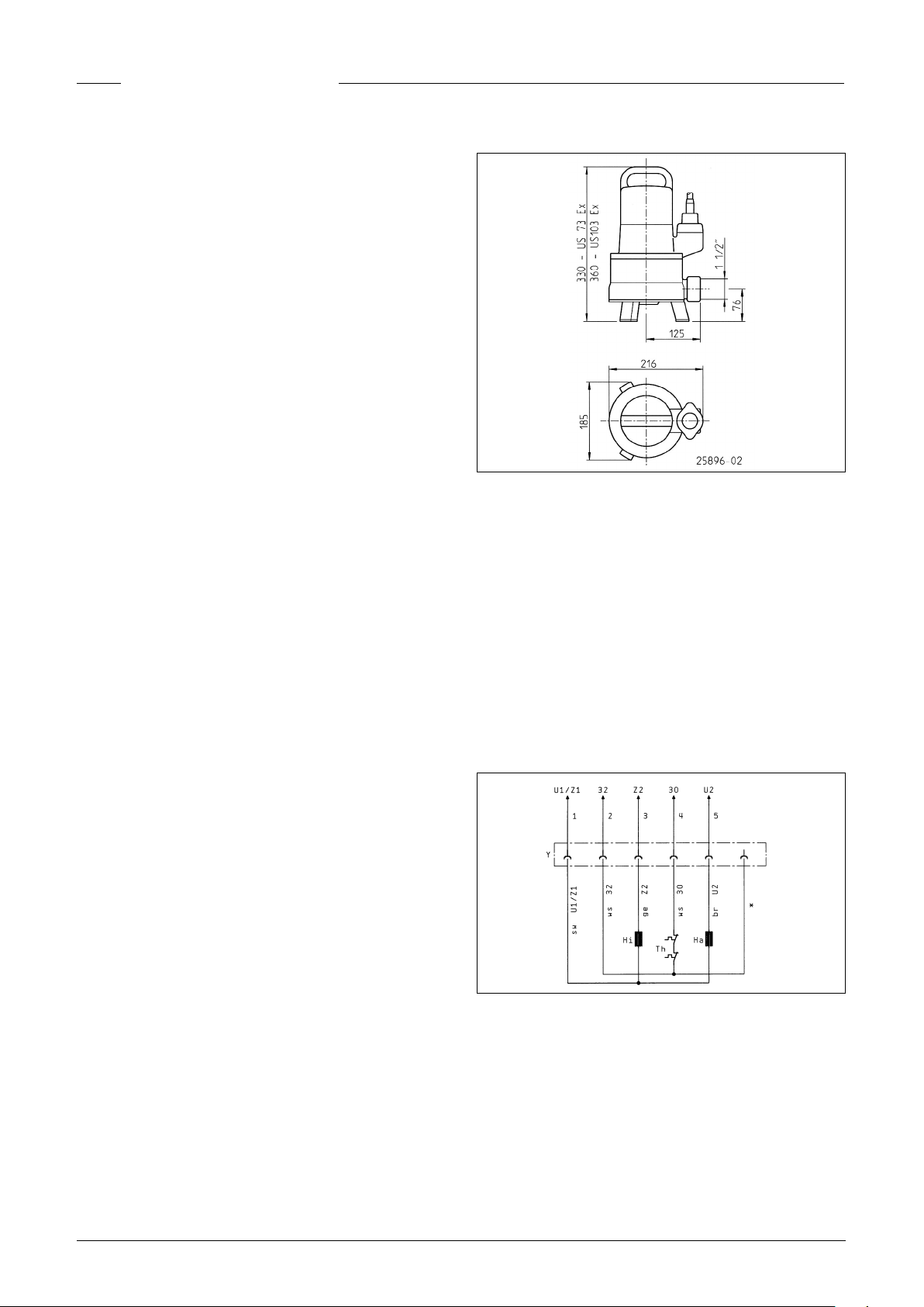
Maße [mm]
ELEKTROANSCHLUSS
Durch den Einsatz unserer Steuerungen haben Sie die Gewissheit, dass die Forderungen aus der EU-Baumusterprüfbescheinigung erfüllt sind.
HINWEIS! Nur eine Elektrofachkraft darf an Pumpe oder Steuerung Elektroarbeiten vornehmen.
Die jeweils gültigen Normen (z.B. EN), landesspezischen Vorschriften (z.B. VDE) sowie die Vorschriften der örtlichen Versorgungsnetzbetreiber sind zu beachten.
HINWEIS! Leitungsende niemals ins Wasser legen! Eventuell
eindringendes Wasser kann zu Störungen führen.
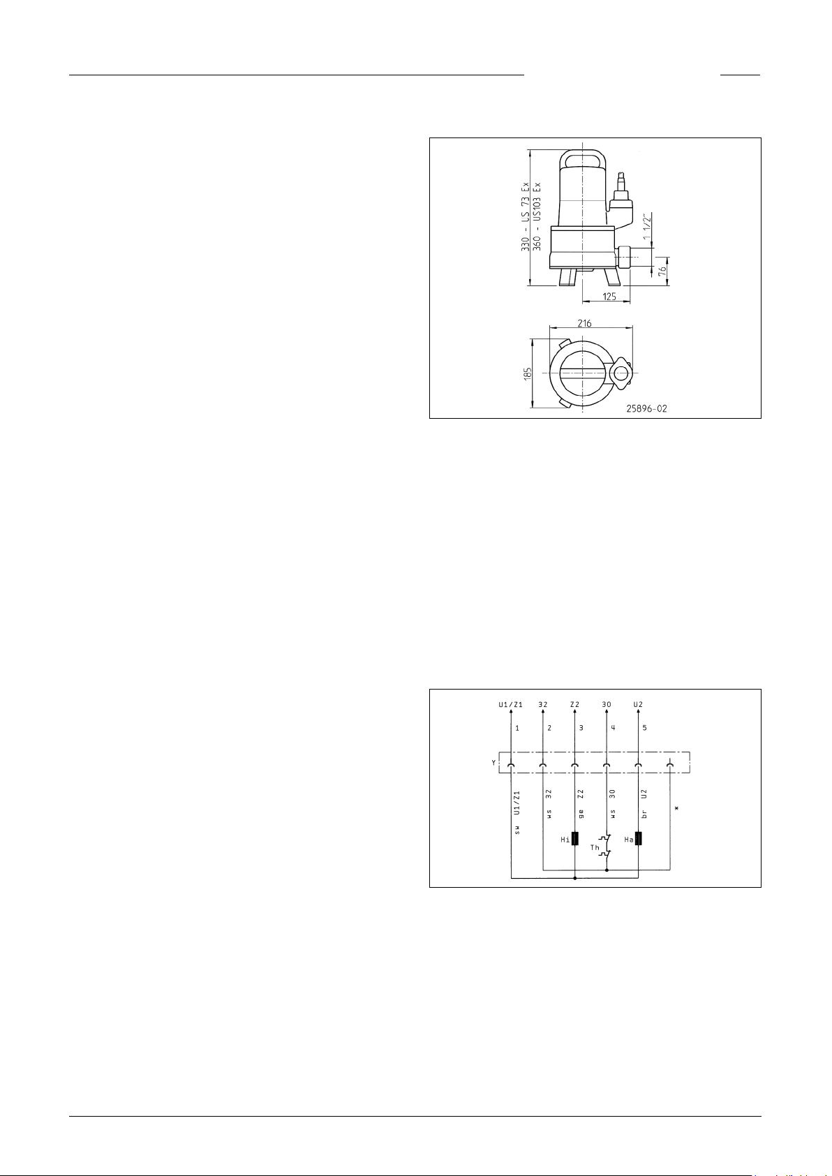
Schaltung für Wechselstrom-Pumpen (24089)
Betriebsarten
bei 40° C Fördermediumtemperatur:
Motor eingetaucht: Dauerbetrieb S1
Motor aufgetaucht: Kurzzeitbetrieb S2; s. Techn. Daten
Motor aufgetaucht: Aussetzbetrieb S3; s. Techn. Daten
Bei Lagerung im Trockenen ist die Tauchpumpe bis -20º C
frostsicher. Eingebaut darf sie im Wasser jedoch nicht einfrieren.
Transport
Die Pumpe soll grundsätzlich am Tragegriff und nicht am Zuleitungskabel angehoben werden! Das Versenken der Pumpe
in tiefere Schächte oder Gruben ist nur mit Seil oder Kette vorzunehmen.
4
Wechselstrompumpen US...,Ex dürfen ohne Steuerung nicht
betrieben werden.
Die Pumpen in Wechselstromausführung sind durch 2 Wicklungsthermostate und einen Motorschutz in der Steuerung
AD 4 XE oder AD 8 XE geschützt. Die beiden Betriebskondensatoren in der Steuerung müssen den Bemessungen entsprechen, die in der Baumusterprüfbescheinigung beschrieben
sind:
Kapazität 8 µF bzw. 20 µF Toleranz ± 10%
Betriebsspannung 400 V Betriebsart DB
DEUTSCH
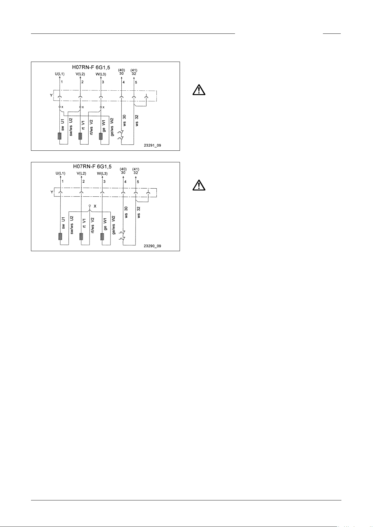
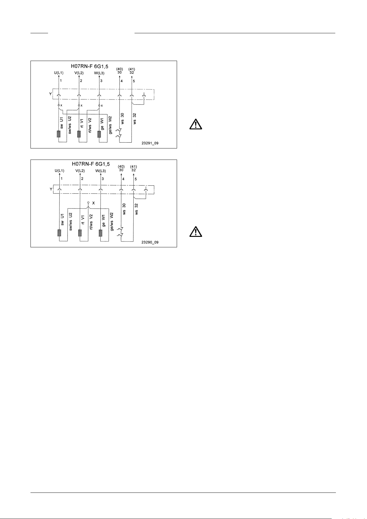
Schaltung für niedrige Spannung (23291)
Schaltung für hohe Spannung (23290)
gehäuse. Laute Betriebsgeräusche oder zu geringe Pumpenleistung der bereits eingebauten Pumpe deuten ebenfalls auf
falsche Drehrichtung hin. Bei falscher Drehrichtung müssen 2
Phasen der Zuleitung getauscht werden.
VORSICHT!
Der Anlaufruck kann mit großer Kraft erfolgen.
Wicklungsthermostate
HINWEIS! Zusätzlich zum Überstrom-Auslöser bzw. Motorschutzschalter sind die in der Motorwicklung eingebauten
Thermostate anzuschließen. Sie sind für 250 V / 1,2 A (cos phi
0,6) geeignet und anschlussmäßig mit 30 und 32 bezeichnet.
Die Thermostate sind so anzuschließen, dass beim Erreichen
der Ansprechtemperatur der Motor über den Steuerstromkreis
abgeschaltet wird. Eine automatische Wiedereinschaltung
darf nach Abkühlung der Wicklung nicht möglich sein.
WARNUNG!
Nach dem Abschalten durch die Temperatur-Begrenzer muss
erst die Störungsursache beseitigt werden. Erst dann darf von
Hand wieder eingeschaltet werden.
Die Wiedereinschaltsperre muss "nullspannungssicher" sein,
d.h. auch nach einem Spannungsausfall muss die Sperre er-
halten bleiben (in Europa Richtlinie 94/9/EG Anhang II 1.5, EN
60079-17 Tab1, B10).
Schaltungsänderungen sind unter Verwendung von Quetschverbindern (X) zwischen Coni-Steckverbindung (Y) und Einbaumotor vorzunehmen. Die neue Quetschverbindung muss fachgerecht hergestellt werden.
Als Vorsicherungen für die Pumpe sind nur träge Sicherungen
oder Automaten mit C- oder D-Charakteristik einzusetzen. Erforderliche Absicherung bei Direkt-Start: 16 A.
Die Pumpe ist durch einen Überstrom-Auslöser zu schützen.
Einstellung bei Direkt-Start = Nennstrom.
Wenn die Schutzeinrichtung ausgelöst hat, ist vor dem Wiedereinschalten die Störungsursache zu beseitigen.
Potentialausgleich
Nach EN 60079-14 und EN 1127-1 muss in explosionsgefährdeten Bereichen bei Betriebsmitteln mit Schutzleitern im TN/
TT-Netz ein zusätzlicher Potentialausgleich installiert werden.
Ex-Pumpen besitzen hierfür eine Anschlussmöglichkeit an der
Kabeleinführung. Dimensionierung z.B. in Deutschland nach
VDE 0100 Teil 540.
Nach Stellungnahme des TÜV Nord vom März 2008 ist für
Beton- und Kunststoffschächte von Pentair Jung Pumpen in
Ex-Zone 1 und 2 kein zusätzlicher örtlicher Potentialausgleich
notwendig.
Ausnahme: Wenn leitfähige Teile, wie z.B. ein Kabelschutz aus
Wellrohr oder ein metallisches Druckrohr von außen an den
Schachtanschluss führen. In diesen Fällen ist eine elektrisch
leitfähige Verbindung mit dem Gehäuse der Pumpe(n) herzustellen. Für diese Verbindung sollte aus Korrosionsschutzgründen Edelstahl verwendet werden.
Drehrichtung
Gilt nur für Drehstrompumpen. Vor dem Einbau ist die Drehrichtung zu prüfen! Bei richtiger Drehrichtung erfolgt der
Anlaufruck entgegen dem Drehrichtungspfeil auf dem Motor-
Betrieb an einem Frequenzumrichter
Frequenzumrichter dürfen nur zur Drehzahl-Regulierung von
Dreh strom-Pumpen in Sonderausführung eingesetzt werden!
Aus hydraulischen Gründen empfehlen wir keinen Betrieb unterhalb 30 Hz.
Wechselstrompumpen sind generell ungeeignet.
HINWEIS! Aus physikalischen Gründen können Pumpen nicht
mit einer höheren Frequenz als auf dem Typenschild angegeben betrieben werden. Bei einer Frequenzerhöhung über den
Typenschildwert hinaus steigt die Leistungsaufnahme und der
Motor wird überlastet.
Bei Drehstrom-Pumpen in Sonderausführung für den Frequenzumrichterbetrieb ist der Motortyp auf dem Typenschild
mit einem zusätzlichen "K" gekennzeichnet (z.B. D90-2/75 CK).
Zusätzlich haben diese Pumpen am Leitungsende einen Aufkleber, der auf die Betriebsmöglichkeit mit einem Frequenzumrichter hinweist.
Die Motoren sind mit Kaltleitern (PTC) als Wicklungsschutz
ausgestattet. An den Klemmen 40 und 41 des Wicklungsschutzes darf keine Spannung > 2,5 Volt gelegt werden! Bei explosionsgeschützten Pumpen ist außerdem ein bauartgeprüftes
Auslösegerät erforderlich, dass die Forderungen der EG-Baumusterprüfung berücksicht.
EINBAU
Die Pumpe muss entsprechend den Beispielen eingebaut werden. Bei Installationen nach DIN EN 12056-4 muss die Druckleitung als Schleife über die örtlich festgelegte Rückstauebene
geführt und mit einem Rückussverhinderer gesichert werden.
Die Mindestießgeschwindigkeit von 0,7 m/s in der Rohrlei-
tung muss eingehalten werden.
5
DEUTSCH
WARNUNG!
Gemäß den Gesetzen und Vorschriften zum Explosionsschutz
dürfen diese Pumpen niemals trocken laufen oder im Schlürfbetrieb arbeiten.
Die Pumpe muss spätestens dann abschalten, wenn der Wasserstand die Oberkante des Pumpengehäuses erreicht (s. Einbaubeispiele). Diese Abschaltung muss über einen separaten
Schaltkreis erfolgen. Der Trockenlauf darf ausschließlich außerhalb des Ex-Bereiches zu Wartungs- und Inspektionszwecken erfolgen.
Bei längerer Druckleitung ist zur Vermeidung von Rohrreibungsverlusten ein entsprechend größerer Rohrquerschnitt
zu wählen.
Bei Bedarf wird für ein dauerhaftes Entlüften des Pumpengehäuses oberhalb des Druckstutzens ein 6-mm-Loch in die
Druckleitung gebohrt.
HINWEIS! Bei einer defekten Pumpe kann ein Teil der Ölkammerfüllung in das Fördermedium entweichen.
Schachtmaße
Einzelanlage mit Standfuß: 40 x 40 cm
Einzelanlage mit Gleitrohr: 40 x 60 cm
Doppelanlage: 60 x 60 cm
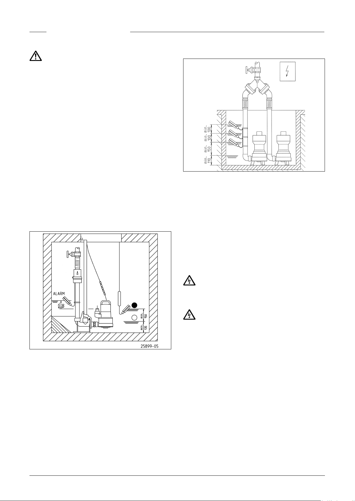
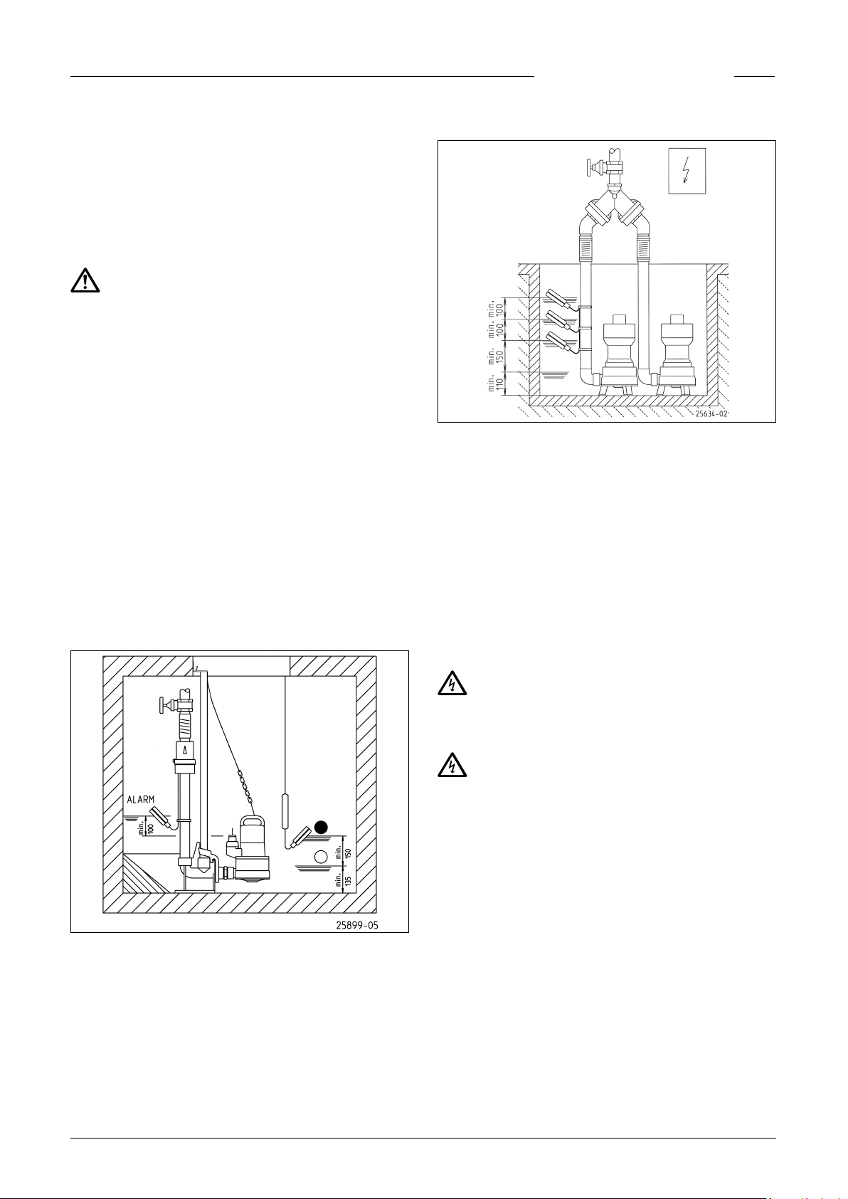
Einbaubeispiel mit Standfuß
Montage: Die Tauchpumpe wird druckseitig mit einem 90º-
Anschluss versehen und dann mit einer Kette in den Schacht
oder die Sammelgrube eingesetzt.
Die Niveauerfassung kann über verschiedene Systeme erfolgen. Besonderheiten und Anforderungen entnehmen Sie der
jeweiligen Betriebsanleitung.
Einbaubeispiel mit Gleitrohr
Montage: Den Kupplungsfuß fest auf dem Boden des Sammel-
schachtes verdübeln und dann die Gleitrohre montieren. Danach die Druckleitung einschließlich der erforderlichen Armaturen wie Rückschlagklappe und Absperrschieber einbauen.
Zum Schluß die Pumpe mit der angeschraubten Kupplungsklaue auf das Gleitrohr setzen und mit einer Kette, die am
Schäkel befestigt wird, hinunterlassen.
Über der Schachtöffnung sollte in ausreichender Höhe eine
Befestigungsmöglichkeit für ein Hebezeug vorgesehen werden.
WARTUNG
Wartung und Inspektion dieses Produktes sind nach EN 120564 und EN 60074-19 vorzunehmen. Um eine dauerhafte Betriebssicherheit Ihrer Anlage zu gewährleisten, empfehlen wir
einen Wartungsvertrag abzuschließen.
WARNUNG!
Vor jeder Arbeit Pumpe und Steuerung vom Netz trennen und
sicherstellen, dass sie von anderen Personen nicht wieder unter Spannung gesetzt werden kann.
WARNUNG!
Das Anschlusskabel auf mechanische und chemische Beschädigungen prüfen. Beschädigte oder geknickte Leitungen müssen durch den Hersteller ersetzt werden.
HINWEIS! Bei Benutzung einer Kette zum Heben der Pumpe
beachten Sie bitte die jeweiligen nationalen Unfallverhütungsvorschriften. Hebezeuge sind regelmäßig durch einen Sachverständigen nach den gesetzlichen Vorschriften zu prüfen.
Ölkontrolle
Die Ölkammer ist durch eine Messingschraube nach außen abgedichtet. Zur Kontrolle der Gleitringdichtung wird das Öl der
Ölkammer einschließlich der Restmenge abgelassen und in
einem sauberen Messbecher aufgefangen.
• Ist das Öl mit Wasser durchsetzt (milchig), muss ein Ölwech-
sel gemacht werden. Nach weiteren 300 Betriebsstunden,
max. jedoch nach 6 Monaten, erneut kontrollieren!
6

DEUTSCH
• Ist das Öl jedoch mit Wasser und Schmutzstoffen durch-
setzt, muss neben dem Öl auch die Gleitringdichtung ersetzt
werden.
Zur Überwachung der Ölkammer kann, auch nachträglich, die
Elektrode unserer Dichtungskontrolle "DKG-Ex" anstelle der
Messingschraube der Ölkammer montiert werden.
Ölwechsel
Zur Erhaltung der Funktionssicherheit ist ein erster Ölwechsel
nach 300 und weitere Ölwechsel nach jeweils 1000 Betriebsstunden durchzuführen.
Bei geringeren Betriebsstunden ist aber mindestens einmal
jährlich ein Ölwechsel durchzuführen.
Wird Abwasser mit stark abrasiven Beimengungen gefördert,
sind die Ölwechsel in entsprechend kürzeren Intervallen vorzusehen.
Für den Wechsel der Ölkammerfüllung ist Hydraulik-Mineralöl
HLP der Viskositätsklasse 22 bis 46 zu verwenden, z.B. Esso
Nuto oder Mobil DTE 22, DTE 24, DTE 25.
Die Füllmenge beträgt 390 cm³.
HINWEIS! Die Ölkammer darf nur mit der angegebenen Öl-
menge gefüllt werden. Ein Überfüllen führt zur Zerstörung der
Pumpe.
Reinigung
Zur Reinigung des Laufrades bei Blockierung oder Verstopfung, werden die Innensechskantschrauben an der Unterseite
der Pumpe herausgedreht, die eventuell vorhandenen Standfüße abgenommen und der Deckel aus dem Pumpengehäuse
gezogen. Jetzt kann das Laufrad gereinigt werden.
VORSICHT!
Abgenutzte Laufräder können scharfe Kanten haben.
Das Anzugsdrehmoment MA für Schraubenwerkstoff A2 be-
trägt für M6: 8 Nm.
KLEINE HILFE BEI STÖRUNGEN
Pumpe läuft nicht
• Netzspannung prüfen (keinen Prüfstift verwenden)
• Sicherung defekt = eventuell zu schwach (siehe Elektro-
Anschluss)
• Netzzuleitung beschädigt = Reparatur nur durch den Her-
steller
Pumpe läuft, aber fördert nicht
• Druckleitung bzw. Schlauch entleeren, damit die Rück-
schlagklappe öffnet und die Luft aus dem Pumpengehäuse
entweichen kann
Laufrad blockiert
• Fest- und Faserstoffe haben sich im Pumpengehäuse fest-
gesetzt = reinigen
Verminderte Förderleistung
• Pumpengehäuse verstopft = reinigen
• Laufrad verschlissen = austauschen
• Falsche Drehrichtung bei Drehstrom = 2 Phasen der Zulei-
tung von einer Elek trofachkraft wechseln lassen
7

ENGLISH
You have purchased a product made by Pentair Jung Pumpen and with it, therefore, also excellent quality and service.
Secure this service by carrying out the installation works
in accordance with the instructions, so that our product
can perform its task to your complete satisfaction. Please
remember that damage caused by incorrect installation or
handling will adversely affect the guarantee. Therefore please adhere to the instructions in this manual!
This appliance can be used by children aged 8 years or over
and by persons with limited physical, sensory or intellectual
capabilities, or with limited experience and knowledge, provided that they are supervised or have been instructed in
the safe use of the appliance and are aware of the dangers
involved. Children must not be allowed to play with the appliance. Cleaning and user maintenance must not be carried
out by children unless they are supervised.
Damage prevention in case of failure
Like any other electrical device, this product may fail due to a
lack of mains voltage or a technical defect.
If damage (including consequential damage) can occur as a result of product failure, the following precautions can be taken
at your discretion:
• Installation of a water level dependent (under circumstanc-
es, mains-independent) alarm system, so that the alarm can
be heard before damage occurs.
• Inspection of the collecting tank/chamber for tightness up
to the top edge before – or at the latest, during – installation
or operation of the product.
• Installation of backow protection for drainage units that can
be damaged by wastewater leakage upon product failure.
• Installation of a further product that can compensate in
case of failure of the other product (e.g. duplex unit).
• Installation of an emergency power generator.
As these precautions serve to prevent or minimise consequential damage upon product failure, they are to be strictly
observed as the manufacturer’s guideline – in line with the
standard DIN EN specications as state of the art – when using
the product (Higher Regional Court Frankfurt/Main, Ref.: 2 U
205/11, 06/15/2012).
SAFETY INSTRUCTIONS
This instruction manual contains essential information that
must be observed during installation, operation and servicing. It is therefore important that the installer and the responsible technician/operator read this instruction manual before
the equipment is installed and put into operation. The manual
must always be available at the location where the pump or the
plant is installed.
Failure to observe the safety instructions can lead to the loss
of all indemnity.
In this instruction manual, safety information is distinctly labelled with particular symbols. Disregarding this information
can be dangerous.
General danger to people
Warning of electrical voltage
NOTICE! NOTICE!
Qualication and training of personnel
All personnel involved with the operation, servicing, inspection
and installation of the equipment must be suitably qualied
for this work and must have studied the instruction manual in
depth to ensure that they are suciently conversant with its
contents. The supervision, competence and areas of responsibility of the personnel must be precisely regulated by the operator. If the personnel do not have the necessary skills, they
must be instructed and trained accordingly.
Safety-conscious working
The safety instructions in this instruction manual, the existing
national regulations regarding accident prevention, and any
internal working, operating and safety regulations must be adhered to.
Safety instructions for the operator/user
All legal regulations, local directives and safety regulations
must be adhered to.
The possibility of danger due to electrical energy must be prevented.
Leakages of dangerous (e.g. explosive, toxic, hot) substances
must be discharged such that no danger to people or the environment occurs. Legal regulations must be observed.
Safety instructions for installation, inspection and maintenance works
As a basic principle, works may only be carried out to the equipment when it is shut down. Pumps or plant that convey harmful
substances must be decontaminated.
All safety and protection components must be re-tted and/or
made operational immediately after the works have been completed. Their effectiveness must be checked before restarting,
taking into account the current regulations and stipulations.
Unauthorised modications, manufacture of spare parts
The equipment may only be modied or altered in agreement
with the manufacturer. The use of original spare parts and
accessories approved by the manufacturer is important for
safety reasons. The use of other parts can result in liability for
consequential damage being rescinded.
Unauthorised operating methods
The operational safety of the supplied equipment is only guaranteed if the equipment is used for its intended purpose. The
limiting values given in the "Technical Data" section may not be
exceeded under any circumstances.
Instructions regarding accident prevention
Before commencing servicing or maintenance works, cordon
off the working area and check that the lifting gear is in perfect
condition.
Never work alone. Always wear a hard hat, safety glasses and
safety shoes and, if necessary, a suitable safety belt.
Before carrying out welding works or using electrical devices,
check to ensure there is no danger of explosion.
People working in wastewater systems must be vaccinated
against the pathogens that may be found there. For the sake of
your health, be sure to pay meticulous attention to cleanliness
wherever you are working.
Make sure that there are no toxic gases in the working area.
Observe the health and safety at work regulations and make
Danger to equipment and operation
8
ENGLISH
sure that a rst-aid kit is to hand.
In some cases, the pump and the pumping medium may be hot
and could cause burns.
For installations in areas subject to explosion hazards, special
regulations apply!
APPLICATION
Explosion-protected submersible pumps from the US series
are suitable for pumping highly polluted or brous wastewater
without stones from collection chambers or other hazardous
areas.
When using the pumps, the relevant national laws as well as
national and local regulations must be complied with, for example:
• Installation of low voltage systems (e.g. VDE 0100 in Germa-
ny)
• Safety and working materials (e.g., BetrSichV and BGR 500
in Germany)
• Safety in wastewater systems (e.g., GUV-VC5, GUV-R104 and
GUV-R126 in Germany)
• Electrical systems and operating resources (e.g., GUV-VA2
in Germany)
• Explosion protection EN 60079-0, EN 60079-1 and EN 1127-1.
For non-standard utilisation conditions in areas subject to explosion hazards, please ask the local authority responsible. In
Germany, this would be, for example, the Trade Supervisory
Centre (Gewerbeaufsicht), the Technical Inspection Agency
(TÜV), the building authority (Bauamt) or professional organisation (Berufsgenossenschaft).
The installation and operation of this equipment is regulated by
the ordinance concerning the protection of health and safety in
the provision of work equipment and its use at work, concerning
safety when operating installations subject to monitoring, and
concerning the organisation of industrial health and safety at
work, (Betriebssicherheitsverordnung), Article 1.
Dimensions [mm]
ELECTRICAL CONNECTION
By using our controls, you can be sure that the requirements of
the EU type-testing certicate are met.
NOTICE! Only qualied electricians may carry out electrical
works to the pump or the controls.
The relevant standards (such as EN standards), country-speci-
c regulations (such as VDE in Germany), and the regulations of
the local power supply companies must be observed.
NOTICE! Never put the mains plug or a free lead end in water!
If water gets into the plug, this can cause malfunctions and damage.
Circuitry for pumps running on alternating current (24089)
Modes of operation
with the pumped medium at a temperature of 40°C:
Motor submersed: continuous operation S1
Motor at the surface: short duration operation S2; see "Technical Data"
Motor at the surface: intermittent operation S3; see "Technical data"
The submersible pump is frost-resistant down to -20°C (-4°F)
when stored in dry conditions. When installed, however, it
must not be allowed to freeze in the water.
Transport
The pump must always be lifted by the handle and never by
the power supply cable! The pump should only be lowered into
deeper chambers or pits using a rope or chain.
US... EX pumps running on alternating current must not be
used without a control unit.
Pumps in alternating current versions are protected by 2 win-
ding thermostats and a motor contact switch in the AD 4 XE or
AD 8 XE control unit. The two operating condensers in the con-
trol unit must be dimensioned according to the measurements
indicated in the Type Examination Certicate.
Capacity 8 µF or 20 µF
tolerance ± 10%
Operating voltage 400 V
Operating mode continuous operation
9
ENGLISH
Circuitry for low voltage (23291)
Circuitry for high voltage (23290)
Rotational direction
Applies only for three-phase pumps. The rotational direction
must be checked before installation! If the rotational direction
is correct, the start-up jolt should be in the opposite direction
to the rotational direction arrow on the motor housing. The
wrong rotational direction is also indicated if the pump performs inadequately when installed, or if loud noises can be
heard during operation. If the rotational direction is wrong, 2
phases of the supply cable must be swapped over.
CAUTION!
The start-up jolt can be very forceful.
Coil thermostats
NOTICE! In addition to the overload trip and/or the motor protection switch, the thermostats incorporated in the motor windings must be connected. The thermostats are suitable for 250
V / 1.2 A (cos phi = 0.6) and are labelled 30 and 32 for connection
purposes.
The thermostats are to be connected in such a way that the
motor is switched off via the control circuit when the response
temperature is reached. It must not be possible for the motor
to switch on again automatically after the winding has cooled
down.
Alterations to the circuitry are to be made using crimp con-
nectors (X) between the Coni plug connection (Y) and the built-
in motor. The new crimp connection must be professionally
made.
Only slow-blow fuses or automatic fuses with C or D characteristics are to be used as pre-fuses for the pump. Necessary
fuse protection for direct on-line start: 16 A.
The pump must be protected via an overload trip. Setting for
direct on-line start = nominal current.
If the protective device has been triggered, the cause of the
malfunction must be eliminated before switching on again.
Potential equalisation
To comply with EN 60079-14 and EN 1127-1, an additional potential equalisation must be installed for facilities with protective
earth conductors in TN/TT networks in areas subject to explosion hazards. Explosion-protected pumps have a connection
facility for this at the cable entry point. In Germany, for examp-
le, the design must be in accordance with VDE 0100, Part 540
(from the Association of German Electrical Engineers).
According to a statement made by the German inspection au-
thority TÜV Nord in March 2008, it is not necessary to provide
any additional potential equalisation on site for Pentair Jung
Pumpen concrete and plastic pump chambers in Ex zones 1 or 2.
Exception: If conductive parts such as a corrugated tube cable
protection or a metal pressure pipe lead to the pump chamber connection from outside. In these cases, an electrically
conductive connection must be made with the housing of the
pump(s). For reasons of corrosion protection, stainless steel
should be used for this connection.
WARNING!
After an automatic cut-out via the temperature limiters, the
cause of the malfunction must rst be eliminated. Only then
may the motor be switched on again manually.
The restart interlock must be “non-resetting on power failure”,
i.e. the lock must be in place to prevent restarting even after
a power cut (in Europe: Directive 94/9/EC, Appendix II 1.5, EN
60079-17 Table1, B10).
Operation with frequency converter
Frequency converters may only be used for controlling the frequency of special models of three-phase pumps. For hydraulic
reasons we do not recommend operation below 30 Hz.
Alternating current pumps are unsuitable as a rule.
NOTICE! For physical reasons, pumps may not be operated at a
higher frequency than that shown on the type plate. If the frequency increases beyond the value on the type plate, the power input increases and the motor is then overloaded.
For special models of three-phase pumps that are designed for
frequency converter operation, the motor type shown on the
type plate is labelled with an additional “K” (e.g. D90-2/75 CK).
These pumps also have a sticker on the end of the cable that
indicates their suitability for use with a frequency converter.
These motors are tted with PTC thermistors as winding protectors. Voltages > 2.5 volt must not be applied to terminals
40 and 41 of the winding protectors! For explosion protected
pumps, a type-tested tripping unit that complies with the EC
type-testing requirements is also necessary.
10
ENGLISH
Example of installation with pump base:
INSTALLATION
The pump must be installed as shown in the examples. For in-
stallations in accordance with DIN EN 12056-4, the pressure
pipe must be laid in a loop above the local backow level and
protected with a backow prevention valve.
The minimum ow rate of 0.7 m/s in the piping must be adhe-
red to.
WARNING!
In accordance with the explosion protection laws and regulations, these pumps should never be allowed to run dry or to operate in “snore” mode.
The pump must switch off when the water level sinks to the upper edge of the pump housing, at the very latest (see drawings).
This shut-down must be implemented via a separate switching
circuit. Dry running for servicing or inspection purposes may
only take place outside the potentially explosive area.
A correspondingly larger diameter pipe should be used for longer pressure pipelines to avoid pipe friction losses.
The pump housing can be permanently vented if necessary by
drilling a 6 mm hole in the pressure pipe above the pressure
outlet.
NOTICE! If the pump is faulty, part of the contents of the oil
reservoir could escape into the pumped media.
Installation: The submersible pump is tted with a 90° con-
nection and then lowered into the chamber or collecting pit
using a chain.
Level monitoring can be carried out using various systems.
Their specic characteristics and requirements can be found
in the relevant operating manuals.
Dimensions of chamber
Single unit with pump base: 40 x 40 cm
Single unit with guide rail: 40 x 60 cm
Duplex unit: 60 x 60 cm
Example of installation with guide rail
Installation: Fix the coupling base rmly to the oor of the
collection chamber using wall plugs and then mount the guide
rails. Next, install the pressure pipe including the necessary
ttings, such as the non-return valve and shut-off valves.
Finally, t the pump with the screwed-on coupling catch onto
the guide rail and lower it into place using a chain xed to the
shackle.
A xing facility for lifting gear should be provided above the
chamber opening at a sucient height.
SERVICING
Maintenance and inspection of this product must be carried
out in accordance with EN 12056-4 and EN 60074-19. To ensure
continued reliability of service, we recommend that you take
out a service contract.
WARNING!
Before carrying out any work: disconnect the pump and the
control unit from the mains and take action to ensure that no
one else can reconnect them to the power supply.
WARNING!
Check the plug and the mains cable for signs of mechanical
and chemical damage. Damaged or kinked cables must be replaced by the manufacturer.
NOTICE! When using a chain to lift the pump, please observe
the relevant national regulations regarding accident prevention. Lifting gear must be checked regularly by an expert in accordance with the legal regulations.
Oil check
The oil reservoir is sealed on the outside with a brass screw. In
order to check the mechanical seal, the oil, including any residue, must be drained from the oil reservoir and collected in a
clean measuring container.
• If the oil is contaminated with water (milky), an oil change
must be carried out. Check again after a further 300 operating hours, but at the very latest after 6 months!
• However, if the oil is contaminated with both water and pol-
lutants, then not only the oil must be replaced, but the mechanical seal as well.
For monitoring the oil reservoir, it is also possible to retrot the
11

ENGLISH
electrode of our "DKG-Ex" seal leak control device in place of
the brass screw on the oil reservoir.
Changing the oil
To ensure operational reliability, the rst oil change should be
carried out after 300 operating hours, with further oil changes
carried out after every 1000 operating hours.
If the number of operating hours is very low, an oil change
should still be carried out at least once a year.
If wastewater with strongly abrasive constituents is being
pumped, the oil changes should be carried out at correspondingly shorter intervals.
Use HLP hydraulic mineral oil, viscosity class 22 to 46, e.g.
Nuto from ESSO or DTE 22, DTE 24, or DTE 25 from Mobil, to
replace the oil in the oil reservoir.
The lling quantity of oil required is 390 cm³.
Notice! The oil reservoir must only be lled with the specied
quantity of oil. Overlling will result in the pump being rendered
inoperable.
Cleaning
To clean the impeller in the event of an obstacle or blockage,
the hexagon socket screws on the underside of the pump must
be removed, any base feet tted must be taken off and the cover must be lifted off the pump housing. The impeller can then
be removed.
QUICK TIPS FOR REMEDYING
FAULTS
Pump does not work
• Check mains current (do not use a pin gauge)
• Fuse faulty = may be too weak (please refer to the section
entitled Electrical connection)
• Mains supply cable damaged = repair to be carried out by
manufacturer only
Pump runs but does not pump
• Empty the pressure pipe or hose to allow the non-return
valve to open and the air to escape from the pump housing.
Impeller jammed
• Solids and brous matter have become lodged in the pump
housing = clean
Decreased pumping performance
• Pump housing obstructed = clean
• Impeller worn = replace
• Wrong direction of rotation for a three-phase current = ask
a qualied electrician to change 2 phases of the supply line
CAUTION!
Worn impellers can have sharp edges.
Tightening torque MA for A2 screw materials is for M6: 8 Nm.
12

FRANÇAIS
Vous avez opté pour un produit Pentair Jung Pumpen, synonyme de qualité et de performance. Assurez-vous cette
performance par une installation conforme aux directives:
notre produit pourra ainsi remplir sa mission à votre entière
satisfaction. N‘oubliez pas que les dommages consécutifs à
un maniement non conforme porteront préjudice au droit à
la garantie. Veuillez donc respecter les consignes contenues
dans ces instructions !
Cet appareil peut être utilisé par des enfants d'au moins 8
ans ainsi que par les personnes ayant des capacités physiques, sensorielles ou mentales limitées ou qui manquent
d'expérience et de connaissance, dans la mesure où ils sont
surveillés ou s'ils ont reçu des instructions pour une utilisation en toute sécurité de l'appareil et qu'ils comprennent les
risques qui en résultent. Les enfants ne doivent pas jouer
avec l'appareil. Le nettoyage et l'entretien de l'appareil ne
doivent pas être effectués par des enfants si ceux-ci ne
sont pas sous surveillance.
Prévention des dommages en cas de défaillance
Comme tout autre appareil électrique, ce produit peut aussi
tomber en panne suite à une absence de tension ou à un défaut technique.
Si un dommage (également dommage consécutif) se produit
en raison de la défaillance du produit, les dispositions suivantes doivent être prise en particulier selon votre appréciation :
• Montage d’une alarme en fonction du niveau d’eau (éventu-
ellement aussi indépendante du réseau électrique) de sorte
que l’alarme puisse être perçue avant l’apparition d’un dommage.
• Contrôle de l’étanchéité du réservoir collecteur / cuve utili-
sée jusqu’au bord supérieur avant - toutefois au plus tard- le
montage ou la mise en service du produit.
• Montage de protection anti-retour pour les objets de draina-
ge sur lesquels un dommage peut survenir par l’écoulement
d’eau usée après une défaillance du produit.
• Montage d’un autre produit pouvant compenser la défail-
lance du produit (par ex. poste double).
• Montage d’un groupe de secours.
Étant donné que ces dispositions servent à prévenir ou réduire
les dommages consécutifs à une défaillance du produit, elles
sont obligatoires en tant que disposition du fabricant au même
titre que les contraintes normatives de la FR EN comme état
de la technique lors de l’utilisation du produit (OLG Francfort/
Main, n°dossier: 2 U 205/11, 15.06.2012).
CONSIGNES DE SÉCURITÉ
Ces instructions de service contiennent des informations essentielles à respecter lors de l‘installation, de la mise en service et de la maintenance.
Il est impératif que le monteur et l‘exploitant/ le personnel qualié concernés lisent les instructions de service avant le montage et la mise en service.
Les instructions doivent toujours être disponibles sur le lieu
d‘utilisation de la pompe ou de l‘installation.
Le non respect des consignes de sécurité peut entraîner la
perte de tous les droits à réparation du dommage.
Dans ces instructions de service, les consignes de sécurité
sont identiées de manière particulière par des symboles.
Risque d‘ordre général pour les personnes
Avertissement contre la tension électrique
AVIS! AVIS! Danger pour la machine et le fonctionnement
Qualication du personnel
Le personnel pour le maniement, la maintenance, l‘inspection
et le montage doit posséder la qualication nécessaire à ce
type de travaux et il doit s‘être susamment bien informé par
une étude approfondie des instructions de service.
Domaine de responsabilité, l‘exploitant doit régler avec préci-
sion la compétence et le contrôle du personnel.
Si le personnel ne possède pas les connaissances nécessaires,
il est impératif de le former et de l‘instruire.
Travailler en étant soucieux de la sécurité
Il est impératif de respecter les consignes de sécurité, les règlements nationaux en vigueur concernant la prévention des
accidents et les prescriptions internes éventuelles de travail,
de service et de sécurité contenus dans ces instructions.
Consignes de sécurité pour l‘exploitant/ l‘utilisateur
Les directives légales, les règlements locaux et les directives
de sécurité doivent être respectés.
Il faut exclure les risques dus à l‘énergie électrique.
Les fuites de matières dangereuses à refouler (explosives,
toxiques ou brûlantes par exemple) doivent être évacuées de
telle sorte qu‘elles ne représentent aucun danger pour les personnes et l‘environnement. Les directives légales en vigueur
sont à respecter.
Consignes de sécurité pour le montage, les travaux d‘inspection et de maintenance
D‘une manière générale, les travaux à effectuer devront l‘être
exclusivement sur une machine à l‘arrêt. Les pompes ou agrégats refoulant des matières dangereuses pour la santé doivent
être décontaminés.
Directement après la n des travaux, tous les dispositifs de sécurité et de protection doivent être remis en place ou en ser-
vice. Leur ecacité est à contrôler avant la remise en service
et en tenant compte des directives et règlements en vigueur.
Transformation et fabrication de pièces détachées sans
concertation préalable
Une transformation ou une modication de la machine est
uniquement autorisée après consultation du fabricant. Les
pièces détachées d‘origine et les accessoires autorisés par
le fabricant servent à la sécurité. L‘utilisation d‘autres pièces
peut annuler la responsabilité quant aux conséquences en résultant.
Formes de service interdites
La sécurité d‘exploitation de la machine livrée est uniquement
garantie lors d‘une utilisation conforme. Il est absolument interdit de dépasser les valeurs limites indiquées au chapitre «
Caractéristiques technique «.
Consignes concernant la prévention des accidents
Avant les travaux de montage ou de maintenance, barrer la
zone de travail et contrôler le parfait état de l‘engin de levage.
Ne jamais travailler seul et utiliser un casque, des lunettes
13

FRANÇAIS
protectrices et des chaussures de sécurité, ainsi qu‘en cas de
besoin, une ceinture de sécurité adaptée.
Avant d‘effectuer des soudures ou d‘utiliser des appareils élec-
triques, vériez l‘absence de risque d‘explosion.
Les personnes travaillant dans des infrastructures d‘assainissement doivent être vaccinées contre les agents pathogènes
pouvant éventuellement s‘y trouver. D‘autre part, veiller scrupuleusement à l‘hygiène, par égard pour votre santé.
Assurez-vous qu‘aucun gaz toxique ne se trouve dans la zone
de travail.
Respectez les règlements concernant la sécurité de travail et
gardez le nécessaire de premier secours à portée de main.
Dans certains cas, la pompe et le produit peuvent être brûlants, il y a alors risque de brûlure.
Des règles spéciales entrent en vigueur pour les installations
dans les secteurs à risque d‘explosion!
UTILISATION
Les pompes à moteur submersibles antidéagrantes de la série US conviennent au refoulement d'eaux usées contenant des
bres ou d'eaux usées fortement polluées sans pierres provenant de cuves collectrices ou autres récipients exposés aux
explosions.
Lors de l'utilisation des pompes, il est impératif de respecter
les lois nationales en vigueur, les directives ainsi que les dispositions locales telles que par ex.
• réalisation d'installations à basse tension (par ex. VDE 0100
en Allemagne)
• sécurité et moyens de travail (par ex. BetrSichV et BGR 500
en Allemagne)
• sécurité dans les infrastructures techniques d'assainisse-
ment (par ex. GUV-VC5, GUV-R104, GUV-R126 en Allemagne)
• Installations électriques et moyens de consommation (par
ex. GUV-VA2 en Allemagne)
• Protection antidéagrante EN 60079-0 , EN 60079-1 et EN
1127-1.
Veuillez vous adresser aux institutions locales compétentes
pour les conditions d'utilisation différentes dans les zones à
risque d'explosion. En Allemagne, il s'agit par ex. de l'Inspection
du travail, du Service de contrôle TÜV, du Service d'urbanisme
ou de la Caisse professionnelle d'assurances sociales.
L'installation et le fonctionnement de ces installations sont réglés dans la directive relative à la sécurité et à la protection de
la santé lors de la mise en place de moyens de travail et de leur
utilisation lors du travail, à la sécurité lors du fonctionnement
d'installations nécessitant une surveillance et à l'organisation
de la sécurité du travail dans les entreprises, Article 1 Règlement sur la sécurité des entreprises (BetrSichV).
Transport
La pompe doit toujours être soulevée par la poignée de transport et non par le câble d'alimentation ! L'immersion de la
pompe dans des cuves ou fosses plus profondes doit obligatoirement être effectuée à l'aide d'une corde ou une chaîne.
Dimensions [mm]
BRANCHEMENT ÉLECTRIQUE
L'utilisation de nos unités de commande vous donne la certitude que les exigences de l'attestation d'examen EU de type
sont satisfaites.
AVIS !Tous les travaux de nature électrique à effectuer sur la
pompe ou l'unité de commande doivent être conés à un électricien conrmé.
Observer les normes respectivement en vigueur (par ex. EN),
les directives spéciques au pays (par ex. VDE) ainsi que les directives de l'exploitant local du réseau d'alimentation.
AVIS ! Ne jamais mettre la che de protection du moteur, la pri-
se secteur ou l'extrémité de câble libre dans l'eau ! L'eau qui est
susceptible de s'inltrer peut causer des endommagements.
Câblage pour pompes à courant alternatif (24089)
Modes de fonctionnement
pour une température de 40° C des matières à pomper :
Moteur immergé : fonctionnement permanent S1
Moteur remonté: Fonctionnement de courte durée S2 ; cf.
Caractéristiques techniques
Moteur remonté : Service discontinu S3 ; cf. Caractéristiques
techniques
Stockée au sec, la pompe submersible résiste au gel jusqu'à
-20˚ C. Montée, elle ne doit toutefois pas geler dans l'eau.
14
Les pompes à courant alternatif US... Ex ne doivent pas être
utilisées sans unité de commande.
Les pompes à courant alternatif sont protégées par 2 thermostats d'enroulement et par un relais thermique logés dans le
coffret de la commande AD 4 XE ou AD 8 XE. Les deux condensateurs de service logés dans le coffret de la commande
 Loading...