

Page 1
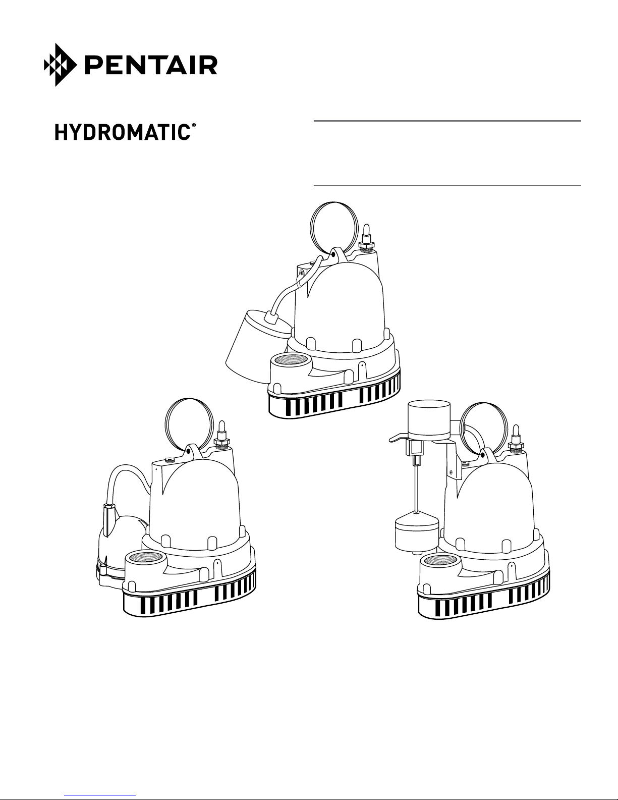
InstallatIon and servIce Manual
W/D/V-A1
Submersible Sump Pump
Manuel d’InstallatIon et d’entretIen
W/D/V-A1
Pompe de puisard submersible
D-A1
NOTICE! TO THE INSTALLER:
Please make sure you provide this
manual to the owner of the pumping
equipment or to the responsible party
who maintains the system.
W-A1
V-A1
REMARQUE ! POUR L’INSTALLATEUR :
Ne pas oublier de remettre ce manuel
au propriétaire de l’équipement de
pompage ou à la personne responsable
de l’entretien du système.
293 WRIGHT STREET, DELAVAN, WI 53115 WWW.HYDROMATIC.COM
PH: 888-957-8677
490 PINEBUSH ROAD, UNIT 4, CAMBRIDGE, ONTARIO, CANADA N1T 0A5
Tél: 800-363-7867
© 2013 Pentair. All Rights Reserved. W-03-398 (12/04/13)
Page 2

1. Provide proper sump
General Information Pump Warning
To help ensure years of troublefree operation, please read the
following manual carefully.
Before Operation:
Read the following instructions
care ful ly. Reasonable care
and safe meth ods should be
practiced. Check local codes and
requirements before installation.
Attention: This manual contains
important information for the safe
use of this product. Read this
manual completely before using
this product and refer to it often
for continued safe product use.
DO NOT THROW AWAY
OR LOSE THIS MANUAL.
Keep it in a safe place so that you
may refer to it often.
WARNING: Before handling
these pumps and controls,
always disconnect the power
first. Do not smoke or use
spark-able electrical devices or
flames in a septic (gaseous) or
possible septic sump.
NOTICE All installations where a
sump pump is permanently-wired
to the source of electrical supply
(control device or junction box)
must be performed only by qualified
personnel using the appropriate
tools, skills, and knowledge of
electrical safety. Such a connection
would not be considered readily
removable if the plug were cut off
the pump’s power cord. Questions
relating to this type of installation
should be directed to your local
code authority.
California Proposition 65 Warning
This product and
related accessories contain
chemicals known to the State of
California to cause cancer, birth
defects or other reproductive harm.
To reduce risk of electrical
shock:
Risk of Electrical Shock:
This pump has not been
investigated for use in swimming
pool areas.
1. This pump is supplied with
a grounding conductor and
ground ing-type attachment
plug. To reduce risk of
electrical shock, be certain
that it is connected only
to a properly grounded,
grounding-type receptacle.
2. Septic tank is to be vented
in accordance with local
plumbing codes.
3. Do not smoke or use sparkable electrical devices or
flame in a septic (gaseous) or
pos si ble septic sump.
4. A septic sump condition may
exist and if entry into sump is
necessary, then (1) provide
proper safety precautions
per OSHA requirements and
(2) do not enter sump until
these precautions are strictly
adhered to.
5. Do not install pump in location
classified as hazardous per
N.E.C., ANSI/NFPA 70 - 2001.
Fail ure to heed above cautions could result in injury or
death.
Pump
Installation
These important instructions
must be followed for satisfactory
performance of your pump. Before
installation, check your local
electrical and plumbing codes.
Minimum Sump Diameter
W-A1 18”
D-A1 12”
V-A1 12”
Approx. Turn-On Level
W-A1 9-1/2”
D-A1 10”
V-A1 7-7/8”
Approx. Turn-Off Level
W-A1 3-1/2”
D-A1 4”
V-A1 3-3/8”
2. Make sure float (automatic
models) hangs free. It should
not come into contact with
side or bottom of sump pit.
3. Make sure sump is free of
string, cloth, nails, gravel, etc.
before in stall ing pump.
4. Do not set pump directly on
the bottom of sump if it is
not solid. Raise the pump by
placing bricks or concrete
blocks un der neath it.
5. Use steel or plastic pipe for
all connecting lines be tween
pump and sewer outlet.
NOTICE Some city regulations
do not allow in stall ing a pump
with plastic pipe. Check local
reg u la tions.
6. A check valve should be
installed in dis charge pipe, at
least twelve inches above the
discharge outlet of the pump.
7. Connect to power source
using 3-prong grounded
115/230 volt AC receptacle.
Do not remove ground pin
from elec tri cal plug. Do not
use an ex ten sion cord.
8. For proper automatic
operation make sure the pump
power cord is plugged into
the back of the “pig gy back” recep tacle on the switch cord.
9. Use pump submerged for
pumping waterlike liquids
(temperature to 120° F).
2
Page 3
CAUTION: Do not pump
flam ma ble liquids, strong
chemi cals or salt water.
10. In applications where the
pump may sit idle for months
at a time, it is recommended
that the pump(s) be cycled
every few months to ensure
the pumping system is working
properly when needed.
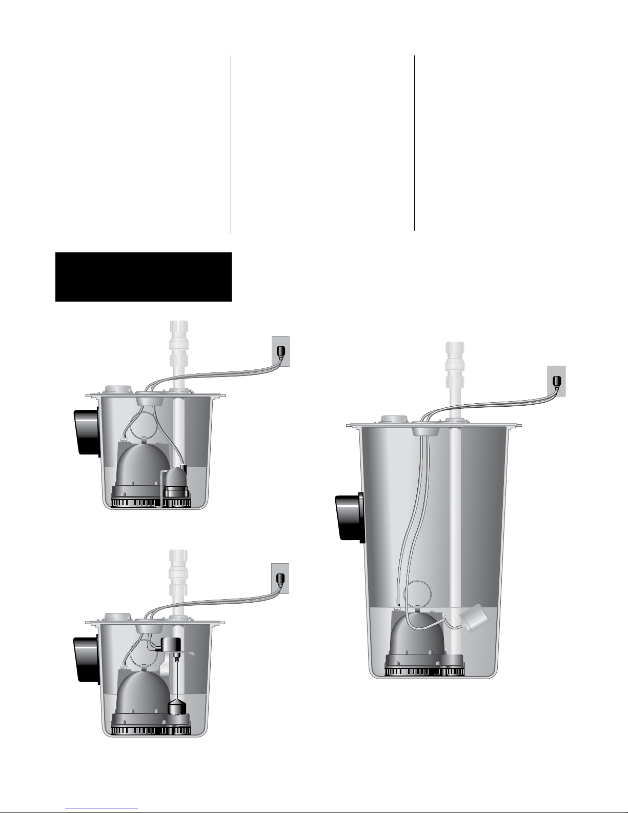
Installation
Drawings
11. An audible alarm, such as
the should be installed for
additional protection against
high water conditions.
Your pump warranty is void if...
• power cord has been cut.
• pump has been used to
pump mud, cement, tar,
abrasives or chem i cals.
• pump has been used
for pumping of hot water
(above 120° F).
•
pump has been
dismantled by other than
authorized service center or
distributor.
D-A1
V-A1
W-A1
3
Page 4
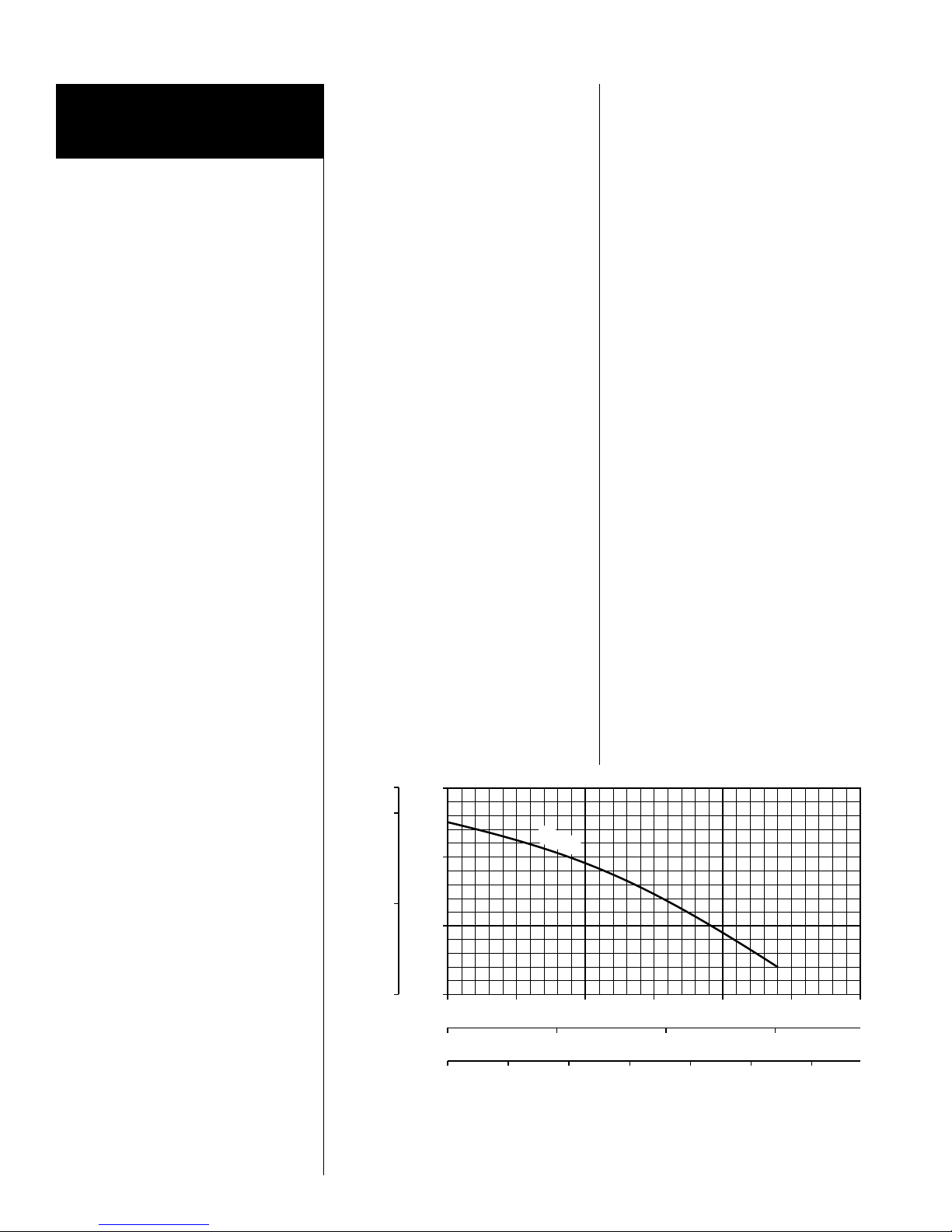
Pump Servicing
30
060
Capacity, US GPM
Servicing should be per formed
only by an authorized service
center.
WARNING: Always disconnect
the pump from power source
before handling or making any
adjustments. Always wear rubber
boots when there is water on the
floor and you must unplug the
pump or make any ad just ments.
NOTICE Automatic thermal
overload protects the sealedin-oil motor. Running dry may
overheat the motor and activate
the overload protector until the
unit cools.
Pump does not run or just
hums.
1. Line circuit breaker may be
off, blown or loose.
2. Water level in sump may be
too low to activate automatic
float or diaphragm switch.
3. Pump and/or switch cord plug
may not be making contact in
receptacle.
4. If pump is using the series
(piggyback) cord plug,
the two plugs may not be
plugged tightly together.
5. Float may be stuck. Be sure
float operates freely in basin.
6. If the unit is being operated
by the optional float control
switch, unplug the pump from
the pig gy back receptacle and
plug the pump directly into
the power source.
If the pump starts each time
it is plugged directly into the
receptacle and does not start
each time when plugged
into the piggyback switch
with the float raised up to
a start position, replace the
complete piggyback switch
assembly and retest with new
assembly.
7. If all symptoms check OK,
motor winding may be open;
take to authorized service
center for check.
Pump runs but does not
deliver water.
1. Check valve may be installed
backward. Arrow on valve
points in direction of flow.
2. Discharge gate valve, if used,
may be closed.
3. Pump may be air locked.
Start and stop several times
by plugging and unplugging
cord. Check vent hole in
pump case for plugging.
Pumps have a small air vent
hole in the impeller cavity
to let out trapped air. If this
hole becomes plugged, pump
may air lock. To break the air
lock, use a small screwdriver
to clear hole in the impeller
cavity.
As a secondary precaution
8
.30 HP
20
Head, meters
Head, feet
4
10
in installations of this type —
1 ⁄16” hole should be drilled in
the discharge pipe below the
check valve. The check valve
should be 12 to 18 inches
above pump discharge. Do
not put check valve directly
into pump discharge opening.
NOTICE In sumps where the
pump is operating daily, air
locking rarely occurs.
4. Pump head may be too
high. Pump cannot deliver
water over 25’ vertical lift.
Horizontal distance does not
affect pumping, except for
friction loss through the pipe.
5. Inlet in pump base may be
clogged. Remove pump and
clean out openings.
6. Impeller or volute openings
may be plugged or partially
plugged. Re move pump and
clean out.
Pump runs and pumps out
sump but does not stop.
1. Float is stuck in up position.
Be sure float is not hung up
and operates freely in basin.
2. Switch contacts may be
stuck; replace switch.
4
00
liters/second
cu meters/hr
0102030405
0.0
0 246810 12
1.0 2.0 3.0
Page 5
Pump runs but delivers only
small amount of water.
1. Pump may be air locked.
Start and stop several times
by plugging and unplugging
cord. Check vent hole in
pump case for plugging.
2. Pump head may be too
high. Pump cannot deliver
water over 25’ vertical lift.
Horizontal distance does
not affect pumping, except
loss due to friction through
discharge pipe.
3. Inlet in pump base may be
clogged. Remove pump and
clean out open ings.
4. Impeller or volute openings
may be plugged or partially
plugged. Re move pump and
clean out.
5. Pump impeller may be
partially clogged causing
motor to run slow, resulting
in motor overload. Clear
impeller.
Fuse blows or circuit break er
trips when pump starts.
1. Inlet in pump base may be
clogged. Remove pump and
clean out open ings.
2. Impeller or volute openings
may be plugged or partially
plugged. Re move pump and
clean out.
3. Pump impeller may be partially
clogged causing motor to
run slow, resulting in motor
overload. Clear impeller.
4. Fuse size or circuit breaker is
too small.
5. Defective motor stator; return
to authorized service center
for verification.
Motor runs for short time then
stops. Then after short period
starts again.
Indicates tripping over load
caused by symp tom shown.
1. Inlet in pump base may be
clogged. Remove pump and
clean out open ings.
2. Impeller or volute openings
may be plugged or partially
plugged. Re move pump and
clean out.
3. Pump impeller may be
partially clogged causing
motor to run slow, resulting
in motor overload.
Clear impeller.
4. Defective motor stator; return
to authorized service center.
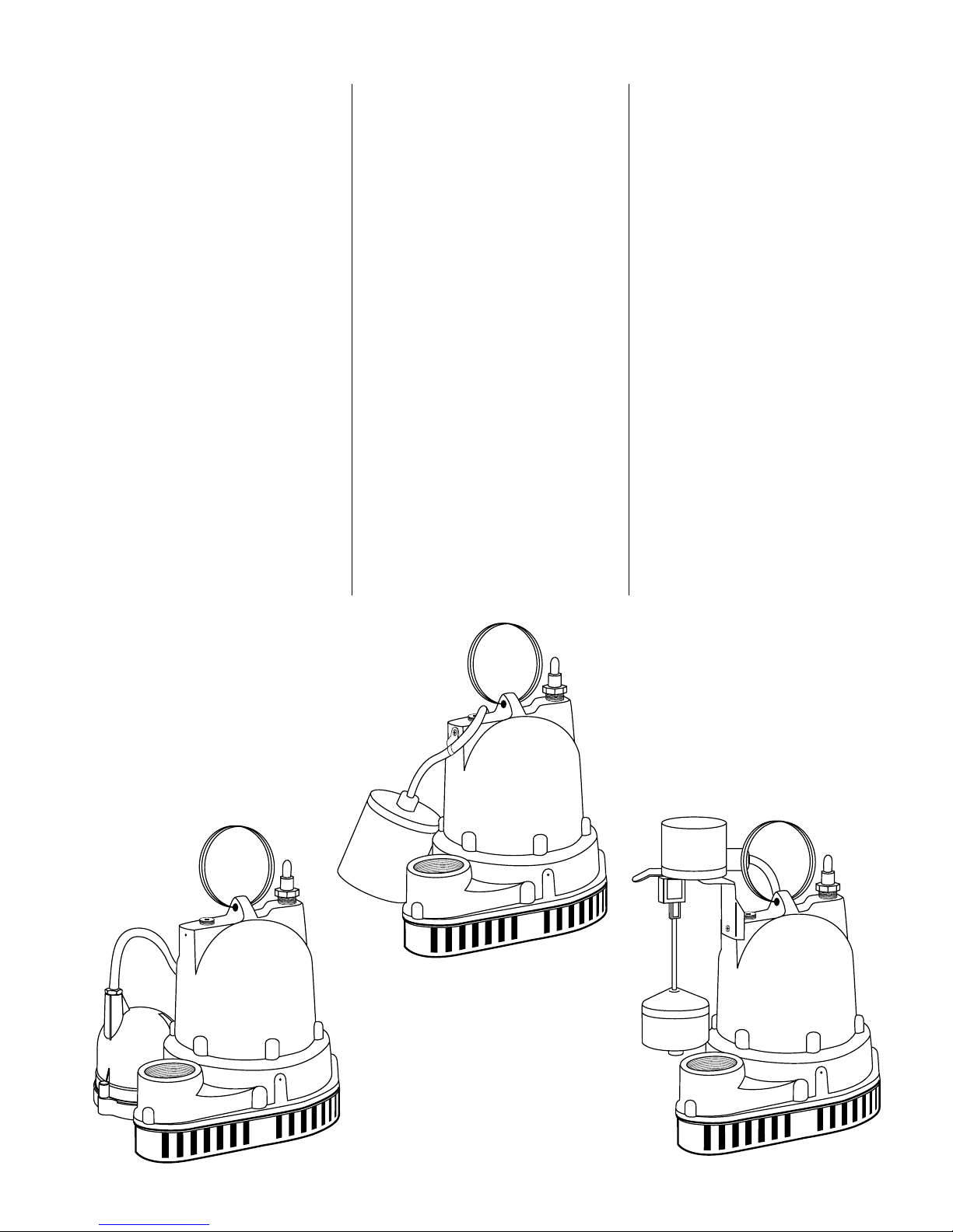
D-A1
W-A1
V-A1
5
Page 6

W/D/V-A1
Parts List
15
13
12
11
10
16
5
1
2
3
4
14
6
7
9
Ref
No. Part No. Description Qty.
1 26230A000 Ring Handle 1
2 14077-000-1 Pipe Plug 1
3 * Motor Housing 1
4 *
5 139-014-1 Seal Ring 1
6 14770-005-1 Pan Screw 5 6
7 8521-101-1 Bottom Plate 1
8 14770-002-1 Pan Screw 6 5
9 8520-002-1 Base 1
10 8498-003-1 Impeller 1
11 21607A001 Shaft Seal 1
12 14770-001-1 Screw 1
*Replace pump
6
Stator/Seal Plate/Rotor and Shaft Assembly
Ref
No. Part No. Description Qty.
13 6000-053-1 Wire with Terminal 1
14 834-030-1 O-Ring 1
15 75-005-1 Cord Nut 1
1
16 14623-010-1 Power Cord 10’ 1
16 14623-020-1 Power Cord 20’ 1
FOR AUTOMATIC OPERATION
12150-110-5 Wide Angle Switch 10’ 1
NOT
SHOWN
12150-120-5 Wide Angle Switch 20’ 1
14974-000-5 Diaphragm Switch 10’ 1
NOT
SHOWN
14974-001-5 Diaphragm Switch 20’ 1
13869-510-5 Vertical Switch 10’ 1
NOT
SHOWN
13869-520-5 Vertical Switch 20’ 1
8
Page 7

THIS PAGE INTENTIONALLY LEFT BLANK
Page 8

Limited Warranty
HYDROMATIC warrants to the original consumer purchaser (“Purchaser” or “You”) of HYDROMATIC Sump Pumps, Effluent
Pumps, Sewage Pumps (other than 2-1/2”), and Package Systems, that they will be free from defects in material and workmanship
for the Warranty Period of 36 months from date of manufacture.
Our warranty will not apply to any product that, in our sole judgement, has been subject to negligence, misapplication, improper
installation, or improper maintenance. Without limiting the foregoing, operating a three phase motor with single phase power
through a phase converter will void the warranty. NOTICE also that three phase motors must be protected by three-leg, ambient
compensated, extra-quick trip overload relays of the recommended size or the warranty is void.
Your only remedy, and HYDROMATIC’s only duty, is that HYDROMATIC repair or replace defective products (at HYDROMATIC’s
choice). You must pay all labor and shipping charges associated with this warranty and must request warranty service through the
installing dealer as soon as a problem is discovered. No request for service will be accepted if received after the Warranty Period
has expired. This warranty is not transferable.
EXCEPTIONS: Hydromatic Special Application Pumps, Battery Back-Up Sump Pumps, Filtered Effluent Pumps, Grinder Pumps,
and 2-1/2” Sewage Pumps are warranted for a period of 12 months from date of purchase or 18 months from date of manufacture,
whichever comes first.
HYDROMATIC SHALL NOT BE LIABLE FOR ANY CONSEQUENTIAL, INCIDENTAL, OR CONTINGENT
DAMAGESWHATSOEVER.
THE FOREGOING LIMITED WARRANTIES ARE EXCLUSIVE AND IN LIEU OF ALL OTHER EXPRESS AND IMPLIED WARRANTIES,
INCLUDING BUT NOT LIMITED TO IMPLIED WARRANTIES OF MERCHANTABILITY AND FITNESS FOR A PARTICULAR
PURPOSE. THE FOREGOING LIMITED WARRANTIES SHALL NOT EXTEND BEYOND THE DURATION PROVIDED HEREIN.
Some states do not allow the exclusion or limitation of incidental or consequential damages or limitations on the duration of an
implied warranty, so the above limitations or exclusions may not apply to You. This warranty gives You specific legal rights and You
may also have other rights which vary from state to state.
This Limited Warranty is effective June 1, 2011 and replaces all undated warranties and warranties dated before June 1, 2011.
HYDROMATIC
293 Wright Street, Delavan, WI 53115
Phone: 888-957-8677 • Fax: 800-426-9446 • Web Site: hydromatic.com
Page 9

Informations
générales
Afin d’assurer des années de
fonctionnement sans problème, veuillez
lire soigneusement ce manuel.
Avant utilisation :
Lire soigneusement les instructions
suivantes. Utiliser des méthodes
d’entretien raisonnables et sécuritaires.
Vérifier les exigences et codes locaux
avant l’installation.
Attention : Le présent manuel contient
des informations importantes pour
une utilisation sûre de ce produit. Lire
complètement ce manuel avant d’utiliser
ce produit et le consulter souvent pour
une utilisation continue et sécuritaire du
produit.
NE PAS JETER NI PERDRE
LE PRÉSENT MANUEL.
Le conserver dans un endroit sûr pour
pouvoir le consulter souvent.
AVERTISSEMENT : AVANT DE
MANIPULER CES POMPES
ET COMMANDES, TOUJOURS
COMMENCER PAR DÉBRANCHER
L’ALIMENTATION ÉLECTRIQUE.
NE PAS FUMER NI UTILISER
D’APPAREILS ÉLECTRIQUES
PRODUISANT DES ÉTINCELLES OU
DES FLAMMES DANS UNE FOSSE
SEPTIQUE (PRÉSENCE DE GAZ) OU
POSSIBLEMENT SEPTIQUE.
REMARQUE Toute installation dans
laquelle une pompe de puisard sera
branchée de façon permanente à une
source d’alimentation électrique (dispositif
de commande ou boîte de connexion)
doit être effectuée exclusivement par du
personnel qualifié utilisant les bons outils
et ayant les bonnes bonnes compétences
et connaissances en matière de sécurité
électrique.
Une telle connexion ne serait pas
considérée comme facilement démontable
si la fiche venait à être coupée du cordon
d’alimentation de la pompe. Les questions
relatives à ce type d’installation doivent
être adressées aux autorités locales
réglementaires.
Avertissement lié à la proposition 65 de la
Californie
Ce produit et les
accessoires connexes contiennent des
produits chimiques reconnus dans l’État
de Californie comme pouvant causer des
cancers, des anomalies congénitales ou
d’autres problèmes de reproduction.
Avertissement
relatif à la pompe
Pour réduire les risques
d’électrocution :
Risque d’électrocution :
Cette pompe n’a pas été conçue pour
1. La pompe est livrée avec un
2. La fosse septique doit être reliée à
3. Ne pas fumer ni utiliser d’appareils
4. Si les conditions sont celles d’une
5. Ne pas installer la pompe dans des
Installation de la
pompe
Il est nécessaire de suivre ces instructions
importantes pour que la pompe fonctionne
de façon satisfaisante.
Avant l’installation, vérifier les codes de
l’électricité et de la plomberie locaux.
être utilisée près d’une piscine.
conducteur de mise à la terre et d’une
fiche de type à prise de terre. Pour
réduire les risques d’électrocution,
s’assurer que la pompe est branchée
sur une prise de terre installée
correctement.
l’air libre conformément aux codes
de plomberie locaux.
électriques produisant des étincelles
ou des flammes dans une fosse
septique (présence de gaz) ou
possiblement septique.
fosse septique et s’il est nécessaire
d’entrer dans le puisard, il faut (1)
prévoir des précautions de sécurité
conformes aux exigences de l’OSHA
et (2) ne pas pénétrer dans le puisard
sans que ces précautions soient
absolument respectées.
endroits classés comme dangereux
selon N.E.C., ANSI/NFPA70 - 2001.
Tout non-respect des précautions
ci-dessus pourrait entraîner des
blessures ou la mort.
1. Prévoir un puisard adapté
Diamètre minimal du puisard
W-A1 18”
D-A1 12”
V-A1 12”
Niveau approx. d’activation
W-A1 9-1/2”
D-A1 10”
V-A1 7-7/8”
Niveau approx. de désactivation
W-A1 3-1/2”
D-A1 4”
V-A1 3-3/8”
2. S’assurer que le flotteur (modèles
automatiques) pend librement. Il ne
doit pas toucher le côté ni le fond du
puisard.
3. Vérifier que le puisard ne contient
pas de ficelle, vêtements, clous,
graviers, etc. avant l’installation de
la pompe.
4. Ne pas poser la pompe directement
sur le fond du puisard si celui-ci n’est
pas solide. Soulever la pompe en
plaçant des briques ou des blocs de
béton en dessous.
5. Utiliser du tuyau en acier ou en
plastique pour toutes les conduites
reliant la pompe à l’égout.
Remarque : Certains règlements
municipaux n’autorisent pas
l’installation d’une pompe avec
un tuyau en plastique. Vérifier la
réglementation locale.
6. Un clapet antiretour doit être installé
dans le tuyau de refoulement, au
moins 12 pouces au-dessus de
l’orifice de refoulement de la pompe.
7. Brancher la fiche d’alimentation sur
une prise C.A. à trois conducteurs
reliée à la terre. Ne pas retirer la
broche de terre de la fiche électrique.
Ne pas utiliser de rallonge.
8. Pour un fonctionnement correct
en mode automatique, s’assurer
que le cordon d’alimentation de la
pompe est branché à l’arrière de la
« prise superposable » sur le cordon
d’alimentation.
9. Utiliser la pompe immergée pour
pomper des liquides comme l’eau
(température jusqu’à 120 °F).
9
Page 10

ATTENTION : Ne pas pomper de
liquides inflammables, de produits
chimiques forts, ni d’eau salée.
10. Dans les applications pour
lesquelles la pompe peut rester sans
fonctionner pendant plusieurs mois,
il est recommandé de faire tourner la
pompe chaque mois pour s’assurer
que le système de pompage
fonctionnera correctement en cas de
besoin.
Dessins
d’installation
11. Un signal d’alarme sonore, comme
le système Q-Alert pour inondation,
devrait être installé pour une
meilleure protection contre les
inondations.
REMARQUE : Le panneau d’alarme
Q-Alert ne peut être utilisé qu’à
l’intérieur. Pour les applications
et des informations sur le produit,
contacter un distributeur.
La garantie de votre pompe est
annulée ...
Si. . . le cordon d’alimentation a été
coupé.
Si. . . la pompe a été utilisée pour
pomper de la boue, du ciment,
du goudron, des abrasifs ou des
produits chimiques.
Si. . . la pompe a été utilisée pour
pomper de l’eau chaude (plus de
120 °F).
Si. . . la pompe a été démontée par
quelqu’un d’autre qu’un centre de
service ou distributeur autorisé.
D-A1
V-A1
W-A1
10
Page 11

Entretien de la
pompe
L’entretien doit être effectué uniquement
par un centre de service autorisé.
AVERTISSEMENT : Toujours
débrancher la pompe de l’alimentation
électrique avant de la manipuler ou de
la modifier. Toujours porter des bottes
en caoutchouc quand il y a de l’eau
sur le sol pour débrancher la pompe
ou faire des modifications.
REMARQUE : Une protection contre
les surcharges thermiques protège
le moteur étanche dans l’huile. Un
fonctionnement à sec peut faire
surchauffer le moteur et activer la
protection contre les surcharges
jusqu’à ce que l’unité refroidisse.
La pompe ne tourne pas ou bourdonne
seulement.
1. Le disjoncteur en ligne est peut-être
déclenché ou mal serré.
2. Le niveau d’eau dans le puisard est
peut-être trop bas pour activer le
flotteur automatique ou l’interrupteur
à diaphragme.
3. La fiche du cordon d’alimentation de
la pompe et/ou de l’interrupteur ne
font pas bon contact dans la prise.
4. Si la pompe utilise la fiche de cordon
série (à prise superposable), les
deux fiches ne sont peut-être pas
bien branchées ensemble.
5. Le flotteur est peut-être coincé.
S’assurer qu’il se déplace librement
dans la cuve.
6. Si l’unité est actionnée par
l’interrupteur de commande à
flotteur en option, débrancher la
pompe de la prise superposable et
la brancher directement à la source
d’alimentation. Si la pompe démarre
chaque fois qu’elle est branchée
directement à la prise et ne démarre
pas quand elle est branchée dans
l’interrupteur superposable avec
le flotteur soulevé en position de
démarrage, remplacer l’ensemble
complet d’interrupteur à flotteur et
tester de nouveau l’ensemble neuf.
7. Si toutes les vérifications ne révèlent
aucun problème, le bobinage du
moteur est peut-être ouvert; porter
la pompe à un centre de service
autorisé pour vérification.
La pompe tourne, mais ne débite pas
d’eau.
1. Le clapet antiretour est peut-être
installé à l’envers. La flèche sur le
clapet est orientée dans le sens du
débit.
2. La vanne d’arrêt de refoulement, le
cas échéant, est peut-être fermée.
3. Le pompe est peut-être bloquée par
l’air. Démarrer et arrêter plusieurs
fois la pompe en branchant et
débranchant le cordon. Vérifier si
le trou d’aération dans le carter de
pompe est bouché.
Les pompes comportent un petit
trou d’aération dans la cavité de
l’impulseur pour laisser échapper
l’air enfermé. Si le trou se bouche,
un bouchon d’air risque de se former
dans la pompe. Pour libérer cette
poche d’air, utiliser un petit tournevis
pour déboucher le trou dans la cavité
de l’impulseur.
Comme précaution supplémentaire
dans les installations de ce type, un
trou de 1⁄16 po devrait être percé
dans le tuyau de refoulement sous le
clapet antiretour. Le clapet antiretour
devrait être situé entre 12 et 18
pouces au-dessus du refoulement
de la pompe. Ne pas placer le
clapet antiretour directement dans
l’ouverture de refoulement de la
pompe.
REMARQUE : Dans les puisards où la
pompe fonctionne quotidiennement,
il est rare que les bouchons d’air se
forment.
4. La hauteur de refoulement de la
pompe est peut-être trop élevée. La
pompe ne peut pas refouler l’eau à
une hauteur verticale supérieure à 25
pi. La distance horizontale n’affecte
pas le pompage, sauf pour la perte
par frottement dans le tuyau.
5. L’entrée dans la base de la pompe
est peut-être bouchée. Déposer la
pompe et nettoyer ses ouvertures.
6. Les ouvertures de l’impulseur ou de
la volute sont peut-être partiellement
ou complètement bouchées.
Déposer la pompe et nettoyer.
La pompe tourne et refoule l’eau du
puisard, mais elle ne s’arrête pas.
1. Le flotteur est coincé en position
haute. S’assurer que le flotteur n’est
pas accroché et se déplace librement
dans la cuve.
2. Les contacts de l’interrupteur
sont peut-être coincés; remplacer
l’interrupteur.
11
Page 12

La pompe tourne, mais ne refoule
qu’une petite quantité d’eau.
1. La pompe est peut-être bloquée par
l’air. Démarrer et arrêter plusieurs
fois la pompe en branchant et
débranchant le cordon.Vérifier si le
trou d’aération dans le carter de
pompe est bouché.
2. La hauteur de refoulement de la
pompe est peut-être trop élevée. La
pompe ne peut pas refouler l’eau
à une hauteur verticale supérieure
à 25 pi. La distance horizontale
n’affecte pas le pompage, sauf pour
la perte par frottement dans le tuyau
de refoulement.
3. L’entrée dans la base de la pompe
est peut-être bouchée. Déposer la
pompe et nettoyer ses ouvertures.
4. Les ouvertures de l’impulseur ou de
la volute sont peut-être partiellement
ou complètement bouchées.
Déposer la pompe et nettoyer.
5. L’impulseur de la pompe est peutêtre partiellement bouché, ce qui
ralentit et surcharge le moteur.
Nettoyer l’impulseur.
Le fusible grille ou le disjoncteur se
déclenche quand la pompe démarre.
1. L’entrée dans la base de la pompe
est peut-être bouchée. Retirer la
pompe et nettoyer ses ouvertures.
2. Les ouvertures de l’impulseur ou de
la volute sont peut-être partiellement
ou complètement bouchées. Retirer
la pompe et nettoyer.
3. L’impulseur de la pompe est peutêtre partiellement bouché, ce qui
ralentit et surcharge le moteur.
Nettoyer l’impulseur.
4. Le calibre du fusible ou du disjoncteur
est peut-être trop faible.
5. Stator du moteur défectueux;
rapporter la pompe dans un centre
de service autorisé pour vérification.
Le moteur fonctionne brièvement, puis
s’arrête. Il redémarre ensuite après
une courte période.
Cela indique que le protecteur
contre les surcharges thermiques se
déclenche à cause des symptômes
indiqués.
1. L’entrée dans la base de la pompe
est peut-être bouchée. Retirer la
pompe et nettoyer ses ouvertures.
2. Les ouvertures de l’impulseur ou de
la volute sont peut-être partiellement
ou complètement bouchées. Retirer
la pompe et nettoyer.
3. L’impulseur de la pompe est peutêtre partiellement bouché, ce qui
ralentit et surcharge le moteur.
Nettoyer l’impulseur.
4. Stator du moteur défectueux;
rapporter la pompe à un centre de
service autorisé.
D-A1
W-A1
V-A1
12
Page 13

W/D/V-A1
Liste des pièces
15
13
12
11
10
16
5
1
2
3
4
14
6
7
9
N°
réf. N° de pièce Description Qté.
1 26230A000 Anneau de maneoeuvre 1
2 14077-000-1 Bouchon de tuyau 1
3 * Carter du moteur 1
4 *
5 139-014-1 Bague d’étanchéité 1
6 14770-005-1 Vis à tête bombée 5 6
7 8521-101-1 Plaque inférieure 1
8 14770-002-1 Vis à tête bombée 6 5
9 8520-002-1 Base 1
10 8498-003-1 Impulseur 1
11 21607A001 Joint d’arbre 1
12 14770-001-1 Vis 1
*Remplacer la pompe.
13
Ensemble de stator/plaque d’étanchéité/
rotor et arbre
N°
réf. N° de pièce Description Qté.
13 6000-053-1 Fil avec borne 1
14 834-030-1 Joint torique 1
15 75-005-1 Écrou de cordon 1
1
16 14623-010-1 Cordon électrique 10 pi 1
16 14623-020-1 Cordon électrique 20 pi 1
POUR FONCTIONNEMENT AUTOMATIQUE
12150-110-5 Interrupteur grand angle 10 pi 1
NOT
SHOWN
12150-120-5 Interrupteur grand angle 20 pi 1
14974-000-5 Interrupteur à diaphragme 10 pi 1
NOT
SHOWN
14974-001-5 Interrupteur à diaphragme 20 pi 1
13869-510-5 Interrupteur vertical 10 pi 1
NOT
SHOWN
13869-520-5 Interrupteur vertical 20 pi 1
8
Page 14

Page intentionnellement laissée en blanc
Page 15

Garantie limitée
HYDROMATIC garantit à l’acheteur/au consommateur d’origine (l’Acheteur) des pompes de puisard, pompes d’effluents, pompes
d’eaux d’égout (à l’exception de la pompe de 2-1/2 po), et les systèmes ensembles HYDROMATIC, que celles-ci seront exemptes de
tout vice de matériaux et de fabrication pendant la période de garantie de 36 mois suivant la date de fabrication.
Nos garanties ne s’appliquent pas aux produits ayant fait l’objet de négligence, d’une mauvaise utilisation, d’une mauvaise installation
ou d’un manque d’entretien adéquat. Sans aucune limitation des présentes, la garantie des moteurs triphasés submersibles sera nulle et
non avenue si ces moteurs sont branchés et fonctionnent sur le courant monophasé par l’intermédiaire d’un déphaseur. Il faut également
NOTER que les moteurs triphasés doivent être protégés par un relais de surcharge tripolaire thermocompensé à déclenchement
extrêmement rapide du calibre recommandé, sinon la garantie sera nulle et non avenue.
Le seul recours de l’Acheteur et la seule responsabilité de HYDROMATIC consistent à réparer ou à remplacer (au choix de
HYDROMATIC) les produits qui se révéleraient défectueux. L’Acheteur s’engage à payer tous les frais de main d’œuvre et d’expédition
du produit couvert par sa garantie et de s’adresser au concessionnaire-installateur ayant procédé à l’installation dès qu’un problème est
découvert pour obtenir un service sous garantie. Aucune demande de service en vertu de sa garantie ne sera acceptée après expiration
de la durée de sa garantie. Ces garanties ne sont pas transférables.
EXCEPTIONS: Les pompes pour applications spéciales, les pompes de puisard de secours à batterie, les pompes d’effluents à filtre, les
pompes broyeuses, et les pompes d’eaux d’égout de 2-1/2 po Hydromatic sont garanties pendant une période de 12 mois suivant la date
d’achat, ou une période de 18 mois suivant la date de fabrication, selon la première occurrence.
HYDROMATIC DÉCLINE TOUTE RESPONSABILITÉ POUR TOUT DOMMAGE INDIRECT OU FORTUIT QUEL QU’IL SOIT.
LA GARANTIE LIMITÉE SUSMENTIONNÉE EST EXCLUSIVE ET REMPLACE TOUTES LES AUTRES GARANTIES EXPRESSES ET TACITES, Y
COMPRIS, MAIS SANS S’Y LIMITER, LES GARANTIES DE QUALITÉ MARCHANDE ET D’ADAPTATION À UN USAGE PARTICULIER. LA
GARANTIE LIMITÉE SUSMENTIONNÉE NE DOIT PAS ÊTRE PROLONGÉE AU-DELÀ DE LA DURÉE PRÉVUE AUX PRÉSENTES.
Certains états, territoires et certaines provinces ne permettent pas l’exclusion ou la limitation des dommages indirects ou fortuits, ni les
limitations relatives à la durée des garanties tacites. Par conséquent, il se peut que les limitations ou les exclusions stipulées dans les
présentes ne s’appliquent pas dans ce cas. Ces garanties accordent des droits juridiques précis, bien que l’on puisse bénéficier d’autres
droits, selon la province, le territoire ou l’état dans lequel on réside.
La présente garantie limitée est entrée en vigueur le 1er juin 2011 et remplace toute garantie non datée ou antérieure à cette date.
HYDROMATIC
293 Wright Street, Delavan, WI 53115
Tél. : 888-957-8677 • Téléc. : 800-426-9446 • Site Web : hydromatic.com
 Loading...