

Page 1
INSTALLATION AND
OPERATOR'S MANUAL
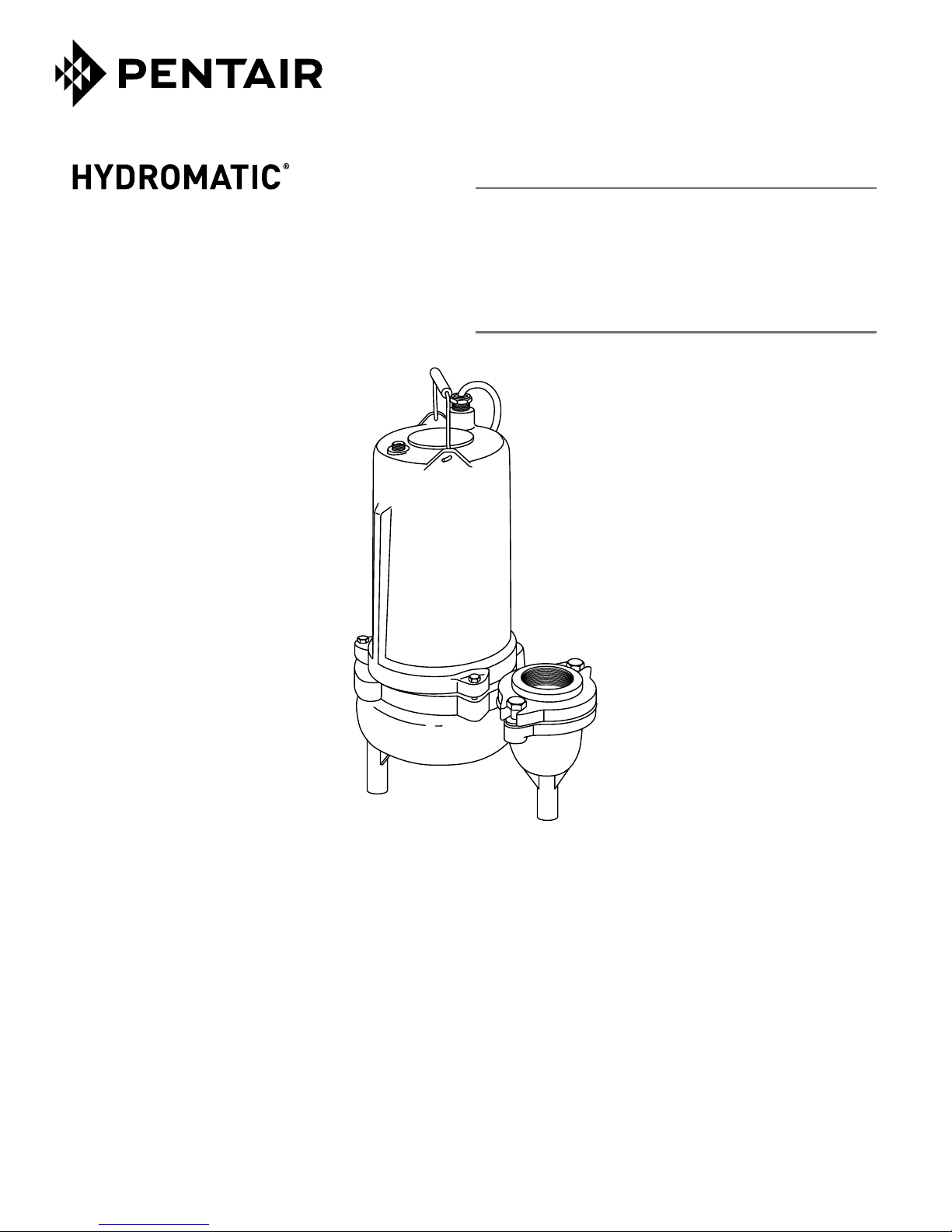
Submersible Sewage
Ejector Pump
INSTALLATION ET MANUEL
DE L'OPéRATEUR
Pompe submersible
d'eauxd'egout
Installation/Operation/Parts
For further operating, installation, or
maintenance assistance:
Call 1-888-957-8677
English ..........Pages 2-13
293 WRIGHT STREET, DELAVAN, WI 53115 WWW.HYDROMATIC.COM
PH: 888-957-8677
269 TRILLIUM DRIVE, KITCHENER, ONTARIO, CANADA N2G 4W5
PH: 519-896-2163
© 2013 Pentair, Ltd. All Rights Reserved. W-03-252 (Rev. 03/04/13)
SK75/100
Installation/Fonctionnement/Pièces
Pour plus de renseignements concernant
l’utilisation, l’installation oul’entretien,
Composer le 1 (888) 957-8677
Français ........Pages 14-26
Page 2
Safety 2
Contents
Important Safety Instructions .......................2
Installation .......................................3
Operation ........................................5
Maintenance ......................................5
Resistance Checks ................................ 6
Reassembly ...................................... 7
Oil fill ........................................... 8
Troubleshooting ..................................9
Repair Parts .....................................10
Warranty .......................................12
Product Specifications ............................13
Important Safety Instructions
SAVE THESE INSTRUCTIONS - This manual contains
important instructions that should be followed during
installation, operation, and maintenance of the product.
Save this manual for future reference.
This is the safety alert symbol. When you see this
symbol on your pump or in this manual, look for one of
the following signal words and be alert to the potential
for personal injury!
indicates a hazard which, if not avoided, will
result in death or serious injury.
indicates a hazard which, if not avoided,
could result in death or serious injury.
indicates a hazard which, if not avoided,
could result in minor or moderate injury.
NOTICE
The manufacturer cannot anticipate every possible
circumstance that might involve a hazard. The warnings
in this manual, and the tags and decals affixed to the unit
are, therefore, not all-inclusive. If you use a procedure
or operating technique that the manufacturer does not
specifically recommend, you must satisfy yourself that it
is safe for you and others. You must also make sure that
the procedure or operating technique that you choose
does not render the system unsafe.
addresses practices not related to personal injury.
Electrically powered sewage pumps normally give many
years of trouble-free service when correctly installed,
maintained, and used. However, unusual circumstances
(interruption of power to the pump, large solids in
the sump, flooding that exceeds the pump’s capacity,
electrical or mechanical failure in the pump, etc.) may
prevent your pump from functioning normally. To prevent
possible damage, consult your dealer about installing a
secondary sewage pump or a high water alarm.
See Troubleshooting in this manual for information
about common sewage pump problems and remedies.
For more information, see your retailer, call Hydromatic
customer service at 1-888-957-8677 or visit our web site
at hydromatic.com.
Hazardous voltage - risk of electrical
shock. Shock can cause serious injury or death.
Failure to follow the warnings below can result in fatal
electricshock.
Burn Hazard.
temperatures. Do not touch an operating motor. To do so
can cause personal injury.
Risk of flooding. If a flexible discharge hose
is used, pump may move around in sump when motor
starts. If it moves far enough so that the switch hits the
side of sump, the switch may stick and prevent the pump
from starting. Make sure the pump is secured so it cannot
move around in the sump.
Motors can operate at high
Page 3
Safety • Installation 3
Hazardous pressure and gas - risk of
explosion and personal injury. Failure to follow the
warnings that follow can result in personal injury.
1. If your basement has water or moisture on the floor,
do not walk on the wet area until all the power
has been turned off. If the shut-off box is in the
basement, call the electric company or the hydro
authority to shut off the service to the house, or call
your local fire department for instructions. Do not
handle the pump or pump motor with wet hands or
when standing on wet or damp surfaces.
2. Connect only to a properly grounded receptacle.
3. All wiring should be performed by a
qualifiedelectrician.
4. Protect the electrical cord from sharp objects, hot
surfaces, oils, and chemicals. Observe the Cord Lift
Warning shown below.
5. Risk of explosion and hazardous gas. Septic
tank must be vented in accordance with local
plumbingcodes.
Do not smoke or use sparkable electrical devices or
flame in a septic (gaseous) or possible septicsump.
If a septic sump condition exists and if entry into
sump is necessary, then (1) provide proper safety
precautions per OSHA requirements and (2) do
not enter sump until these precautions are strictly
adhered to.
Do not install pump in location classified as
hazardous per N.E.C., ANSI/NFPA 70- 2001.
6. Know the pump application, limitations and
potential hazards.
7. Wear safety glasses at all times when working with
the pump.
Keep the work area clean, uncluttered and properly
8.
lighted - secure all unused tools and equipment.
9. Keep visitors at a safe distance from working area.
10. Make the workshop child-proof - with padlocks,
master switches, and by removing starter keys.
11. Release all pressure within the system before
servicing any component.
12.
Provide a means of pressure relief for pumps whose
discharge line can be shut-off or obstructed.
13. Periodically inspect the pump and system
components. Perform routine maintenance
asrequired.
14. Drain all the liquid from the system beforeservicing.
California Proposition 65 Warning
This product and related accessories contain
chemicals known to the State of California to cause
cancer, birth defects or other reproductive harm.
Installation
Thank you for purchasing this Hydromatic® pump. To
help ensure years of trouble-free operation, please read
the manual carefully.
Before installation, check your local electrical and
plumbing codes. Typical sewage pump installations are
shown on the next page.
WARNING
Risk of electrical shock.
Can burn or kill.
Do not lift pump by
powercord.
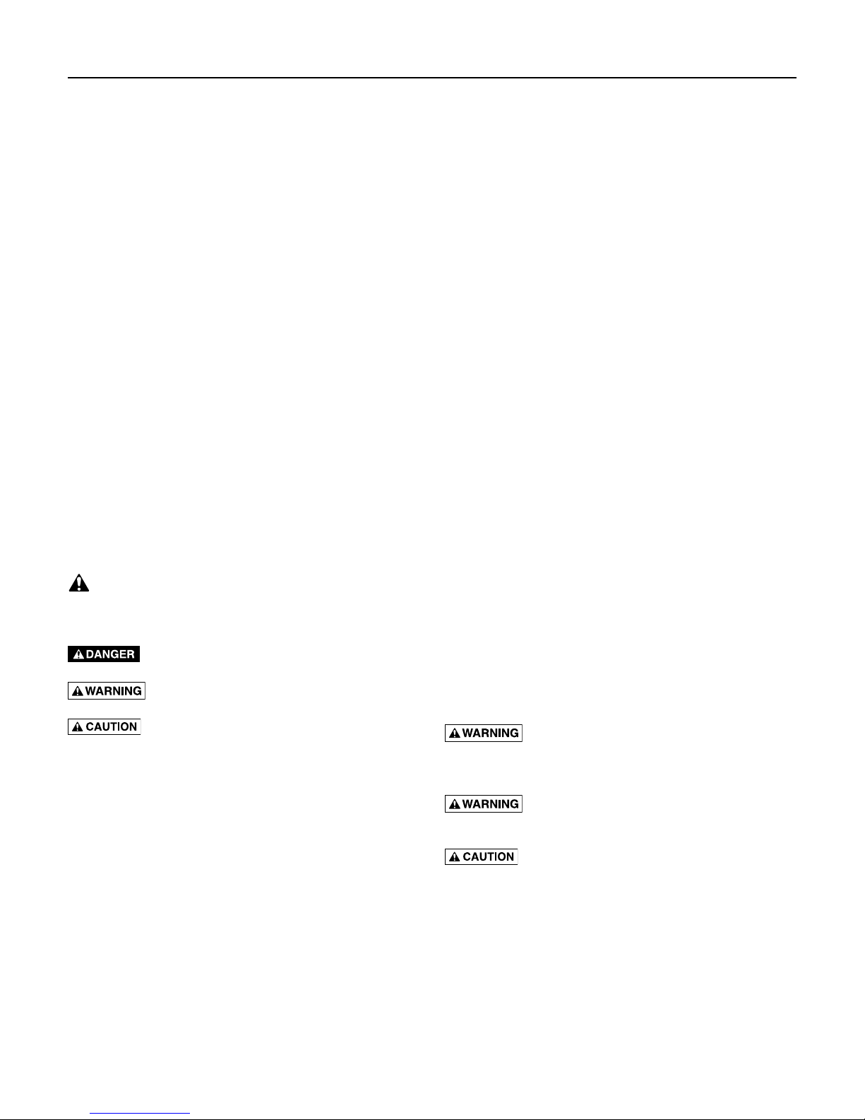
Cord Lift Warning
Risk of electrical shock and fire.
1. Attempting to lift or support the pump by
the power cord can damage cord and cord
connections, expose bare wires, and cause
a fire or electrical shock.
2. Use handle on top of pump for all lifting or
lowering of pump. Disconnect the power
to the pump before doing any work on it
or attempting to remove it from the pit.
3. Lifting or supporting the pump by the
power cord will void the warranty.
Page 4
Installation 4
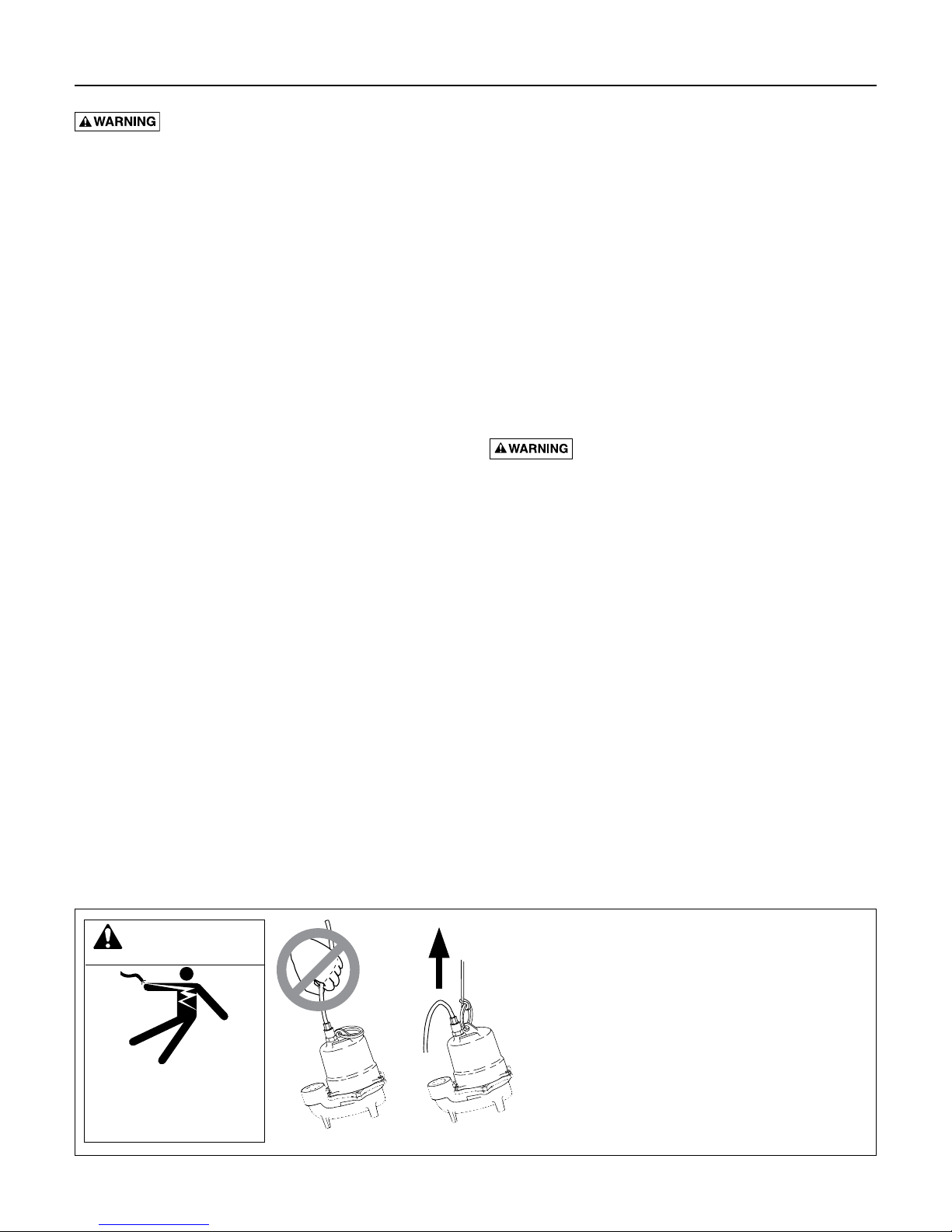
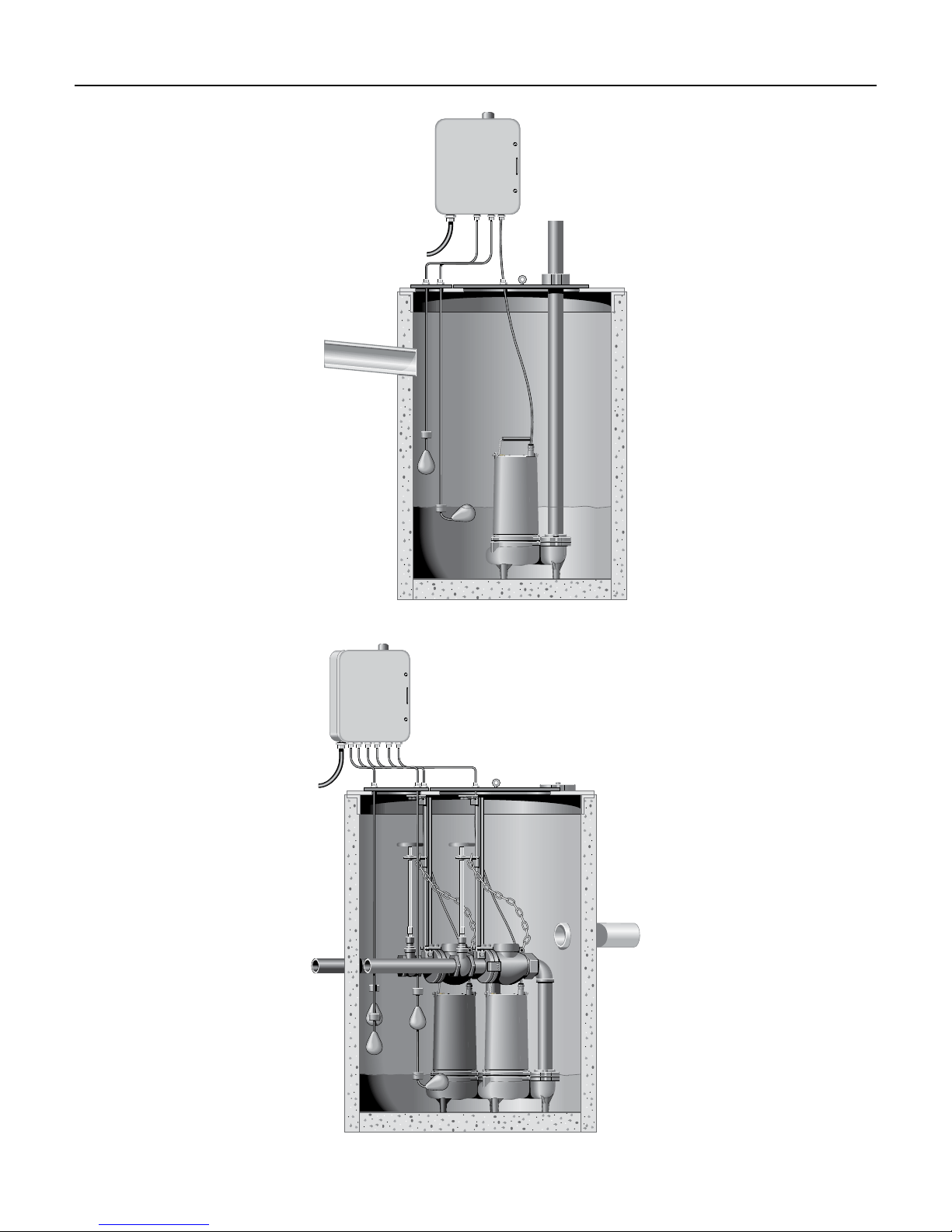
Typical Simplex Installation
Typical Duplex Installation
Page 5

Installation • Operation • Maintenance 5
Follow these guidelines for installation:
1. Provide properly sized pit (see Specifications) on
sewage tank. Minimum pump run time is two
minutes. For maximum pump life, three minutes
isrecommended.
2. Make sure sump is free of string, cloth, nails, gravel,
etc. before installing pump.
3. Do not set pump directly on the bottom of sump pit
if it is not solid. Raise the pump by using bricks or
concrete blocks underneath it.
4. Do not remove ground pin from electrical plug.
5. Do not use an extension cord to operate thispump.
6. For proper automatic operation, make sure the pump
power cord is plugged into the piggyback receptacle
on the switch cord. Three phase models must be
properly connected to a suitable controlpanel.
Do not cut, crimp, or bend single phase switch
power cord. The vent tube needs to “breathe” for
proper operation of switch. This may cause pump
failure and void warranty.
7. Use steel or plastic pipe for all connecting lines
between pump and sewer outlet.
NOTICE: Some city regulations do not
allow installing a pump with plastic pipe.
Checklocalregulations.
8. Use PTFE pipe thread sealant tape on pipe
connections. Do not use ordinary pipe joint
compound on plastic pipe or pump. Pipe joint
compound can attack plastics and damage pump.
9. In applications where the pump may sit idle for
months at a time, it is recommended that the
pump(s) be cycled every month to ensure the
pumping system is working properly whenneeded.
10. A check valve should be installed horizontally in the
discharge pipe.
11. The optional Hydromatic Q Alert is an audible
alarm system for high water conditions. It should be
installed in every sump for greater protection.
NOTICE: Q Alert is for indoor use only. Other
Q Alarm and control panels are available for
outdoor use. Contact your Hydromatic distributor
forapplications.
12. Use pump partially or completely submerged for
pumping waterlike liquids. The pump will pump
solid materials up to 2” (spherical) in diameter. This
pump has not been investigated for use in swimming
pool areas.
Risk of fire. Do not pump flammable
liquids. Strong chemicals or salt water should not
be pumped without consulting your Hydromatic
distributor for proper seals and coatings.
Operation
NOTICE: Do not allow pump to run in a dry sump.
Doing so will void the warranty and may damage
thepump.
An automatic overload protector in the motor will
protect the motor from burning out due to overheating/
overloading. When the motor cools down, the overload
protector will automatically reset.
If overload trips frequently, check for the cause. It could
be a stuck impeller, wrong/low voltage, or electrical
failure in motor. If an electrical failure in the motor is
suspected, have it serviced by a competent repairman.
Maintenance
Read the following instructions carefully before replacing
any parts. Reasonable care and safe methods should be
practiced. Check local codes and requirements before
installation. Only a competent plumber or electrician
should make the installations.
Submerge pump in a disinfectant solution (dilute chlorine
bleach) for at least one hour before disassembling pump.
Check for an obstruction in the impeller by looking
through the suction hole of the pump. The shaft should
turn freely if unobstructed. Keep fingers, clothing or any
material from suction inlet.
The steps described in this section should be performed
only by an authorized service center.
NOTICE: Read all directions before replacing any
parts. Always remove pump from power source
beforeservicing.
The numbers in parentheses, such as "(3)" or "(16)", refer
to item numbers used on the Repair Parts diagram.
Page 6

Maintenance 6
Using an ohmmeter
To be sure wires are not burned off or broken, use an
ohmmeter to perform resistance checks. Set ohmmeter
scale to RX1 scale and check meter by putting both
meter leads together and adjusting the needle knob until
meter reads zero. If meter cannot be adjusted to zero, the
batteries in meter must be replaced.
NOTICE: Always reset meter to zero [0] when going to a
new scale before making any measurements.
If wire is OK, meter needle will go to near zero and stay
there. If meter needle does not move, the wire has an
open and the wire must berepaired orreplaced.
Resistance Checks
1. For single phase (1ø) pumps, attach one meter lead
to the white cord wire of the power cord and the
other meter lead to the black cord wire. This reading
should match the resistance shown in Winding
Resistance Chart, 1ø, 230V.
Model Start Winding Run WInding Total
SK75 6.63 Ω 3.06 Ω 9.69 Ω
SK100 8.57 Ω 2.35 Ω 10.92 Ω
Winding Resistance Chart, 1ø, 230V
For three phase (3ø) pumps, repeat the above
procedure for white and red wires as well as red
and black wires. Each of the three separate readings
should read approximately the same and should
match the resistance shown in Winding Resistance
Chart, 3ø. If no resistance is obtainable for any of the
three phases, either a wire is broken, there is a bad
connection or the winding is defective. Skip Steps 5
and 8 if resistance is OK.
200V 230V 460V 575V
Model
SK75,
SK100
Any one
phase
7.31 Ω 9.66 Ω 38.65 Ω 60.39 Ω
Winding Resistance Chart, 3ø
2. Remove plug (3) from top of housing (4) and pour
oil into a clean glass container. If oil is clear, it
will indicate motor is not burned and there has
been no water leak into the motor. If oil is black,
it will indicate a burned stator. If oil is cloudy, it
will indicate water in motor oil, so all seals should
bereplaced.
Any one
phase
Any one
phase
Any one
phase
3. After draining oil, remove the hex head cap screws
(7) that attach motor housing (4) to volute (11).
Slide motor housing upward 5 to 6 inches in order
to expose power cord wire connections to motor
(5). Disassemble power cord wire connections from
motor and then disassemble power cord from motor
housing. Using the wire leads from the motor, check
the winding resistance with anohmmeter.
For Single Phase (1ø)
4. Attach one meter lead to the white cord wire and the
other meter lead to the black cord wire. See Winding
Resistance Chart, 1ø, 230V for an appropriate
resistance reading. Repeat this procedure for the
black cord wire and red lead wire. This reading is the
start winding resistance. Also repeat this procedure
for the white cord wire and the red cord wire. This
reading is the total motor winding resistance. If no
resistance is obtainable for either the start or main
winding, either there is a bad connection or the
winding isdefective.
For Three Phase (3ø)
5. Twist the three leads of one end of the power cord
together. Then at the other end, with an ohmmeter,
check any two leads. Check the third lead with either
of the first two. If a zero reading is indicated for
any wire, the wire is broken and a new power cord
assembly must be installed.
6. Ground check on stator should be performed using
ohmmeter with scale set to R X 100K. Connect one
meter lead to one lead of the stator and touch the
other meter lead to the housing (4). If the resistance
to the ground is less than 500,000 ohms, there is
moisture in the winding or leakage through stator
insulation. The stator must be dried out and then
rechecked on the ohmmeter. If the resistance is still
less than 500,000 ohms after drying, the stator must
be replaced. A zero reading indicates a direct short,
and the stator will have to be replaced.
Page 7

Maintenance 7
7. If the wiring is grounded and there is no apparent
moisture in the oil (see step 2), the stator must be
checked with a high pot tester.
Shock Hazard. Due to the high voltage,
use extreme care when using the high pot tester.
A dangerous shock can be avoided with careful
handling of the test probes.
Using a voltage of 1500 volts for 115 volt motors
and 2000 volts for 230 volt motors, touch one
probe to the white lead and the other probe to the
stator laminations for only one second. Buzzing
will indicate arcing is occurring at a breakdown of
insulation or a small amount of moisture is present.
The stator will then have to be dried out or replaced.
The high pot test is very destructive. So, each time
the same stator is checked, the voltage should be
lowered about 250 volts. If not, you may cause the
stator to short by breaking down the insulation.
8. Repeat step 4, this time attaching the meter leads
to the stator wires. If a zero reading is obtained, the
winding is defective and the stator must bereplaced.
9. Remove the impeller screw and impeller washer,
then unscrew the impeller (10). Hold the rotor/
shaft assembly with a screwdriver and carefully tap
impeller with a plastic or rubberhammer.
10. Remove the flat head machine screw from seal plate
(9). Remove clamp ring (8) and motor housing (4) off
the seal plate (9).
11. Remove the four hex head stator bolts and lift the
stator from the seal plate (9). A screwdriver can be
inserted under the stator shell in order to remove
thestator.
12. Bump the end of the shaft with a plastic hammer.
This will push the rotating half of the mechanical
seal (14) from the shaft and also push the lower
bearing from the seal plate (9). Now remove the
shaft, rotor and bearing assembly from the seal
plate(9).
13. If water is found in the oil, both the rotating and
stationary halves of the mechanical seal (14) must be
replaced. Remove the stationary seal half by inserting
a screwdriver into seal plate (9) from the top and
tapping lightly with ahammer.
14. Turn the bearing by hand: if it feels rough when
turned or looks rusted, it should be replaced. Use a
bearing puller to remove the bearing.
Reassembly
1. Thoroughly clean the seal (14) and bearing pockets
in the volute. All sand and dirt must beremoved.
2. If the stationary seal half was removed, coat the
replacement stationary seal half with O-ring lube
and use a plastic pusher to press it into the motor
housing (4). Make sure the rubber ring goes in first.
Do not use any sharp objects that may damage
theseal.
3. When installing a replacement bearing, press only
on the inner face and make sure the bearing is flush
against the snap ring. If a press is not available, the
bearing can be tapped onto the shaft using a sleeve
that bears only on the inner face. Pressing on the
outer face will ruin the bearing.
NOTICE: Never pound on the outer face of the
bearing as this will cause bearing damage.
4. Push the shaft, rotor and ball bearing assembly
into the seal plate (9), being careful not to chip the
ceramic of the stationary seal half.
5. Replace the motor (5) if it is visibly burned or if the
ground resistance test or the winding resistance test
has failed. Note that the replacement stator must be
of the same manufacture as the existing rotor or vice
versa. Replace the four stator bolts.
6. Coat the rubber ring on the rotating seal half with
O-ring lube and press the seal onto the shaft with the
rubber ring facing the impeller (10).
NOTICE: Mixing old and new seal parts will cause
immediate seal failure. When replacing seal, replace
both the rotational and the stationary sealhalves.
Page 8

Maintenance 8
7. Attach clamp ring (8) to seal plate (9) and secure
with machine screws.
8. Install impeller (10) onto the pump shaft. On 3ø
models fasten the impeller washer with the impeller
screw to the pump shaft.
9. Turn impeller (10). It should turn freely with nodrag.
10. Place motor/seal plate assembly into the volute
case(11).
11. Place the new O-ring (6) over the seal plateshoulder.
12. Clean motor housing assembly and connect power
cord into cord entry of motor housing.
13. Connect power cord wires to motor connections and
then slide motor housing assembly overmotor.
14. Secure motor housing to volute case with three hex
head screws (7).
15. Reach in the eye of the volute (11) and turn impeller
(10) again. It should turn freely with nodrag.
16. Before filling the motor housing with oil, a seal leak
test should be performed. Apply 7 to 8pounds of
air pressure in the 1/4" NPT tap (3) on the top of the
motor cover and seal chamber.
NOTICE Too much pressure will damage the seal.
Seal would have to be replaced.
Then submerge the pump in water and check for
leaks. If a leak occurs, isolate where it is coming
from and correct the problem by replacing the
failedpart.
7. Hydromatic pumps have a small air vent hole in
the impeller cavity to let out trapped air. If this hole
becomes plugged, pump may air lock. To break the
air lock, use a small screwdriver to clear hole in the
impeller cavity.
As a secondary precaution in installations of this
type, an 1⁄8” hole should be drilled in the discharge
pipe just above the volute. The check valve should
be at least 12inches above pump discharge. Do
not put check valve directly into pump discharge
opening.
NOTICE In sumps where the pump is operating
daily, air locking rarely occurs.
Oil fill
1. After seal leak test is satisfactory, remove unit from
water and wipe or blow off any excess water.
2. Do not put oil in motor with any water present in
motor cavity.
3. Use refined paraffinic transformer oil, ¹Shellflex™
2210 or equivalent.
¹ Shell Oil Company, Texas
4. Slowly fill oil to 1/8" over windings in motor housing
through opening (3). Use an oil fill tube that will go
into holes so that air can escape. Replace plug (3).
NOTICE Do not fill the motor housing completely –
allow air space for expansion.
5. Connect power cord wires to terminals in panel, or
connect power source, and check pump running.
Motor should run smoothly and be free of vibration.
Pump is ready for operation.
Page 9

Troubleshooting 9
Troubleshooting
kill. Disconnect power before attempting any service or
repair work on pump.
Symptom Possible Cause(s) Corrective Action
Motor not running
Pump runs continuously
Little or no effluent
delivered from pump
Pump cycles constantly
Hazardous voltage. Can shock, burn, or
Motor protector tripped.
Open circuit breaker or blown fuse.
Impeller clogged or binding.
Power cable damaged.
Bad control panel. Inspect control panel wiring. Call a licensed electrician.
Defective liquid level switch.
Not enough liquid in wet well to activate
controls.
Liquid level cords tangled Untangle cords for free operation.
Automatic controls defective Try running pump in manual mode. If it runs, the automatic control is at fault.
Liquid level control cords tangled Untangle cords for free operation.
Pump is airlocked.
Flow in matches or exceeds the pump’s
capacity.
Check valve plugged, stuck shut, or
installed backwards.
System head excessive. Consult dealer.
Pump suction plugged. DISCONNECT POWER, pull pump, inspect, and clear as needed.
Wrong voltage or not wired correctly.
Pump is air locked.
Worn or damaged impeller. DISCONNECT POWER, pull pump and inspect impeller. Replace if necessary.
Liquid level controls incorrectly installed
or defective.
No discharge check valve installed. Install discharge check valve.
Discharge check valve stuck open. Repair or replace check valve as necessary.
Sewage wetwell too small. Consult dealer.
Liquid level controls incorrectly installed
or defective.
Pump too small for inlet flow. Consult dealer about larger pump or second pump.
which can cause loss of fingers. Keep hands away from
pump suction inlet when working on or servicing pump.
Allow motor to cool. Make sure pump is completely submerged. Clear debris from volute
and impeller. Check for high amp draw.
Replace fuse or reset breaker. If circuit breaker opens repeatedly, don’t reset it - call a
licensed electrician.
Check amp draw. If it is more than twice the nameplate amps, the impeller is locked.
Bearings and shaft may be damaged. DISCONNECT POWER, clear debris from volute,
impeller, and cutter as needed.
Resistance between power cable and ground should be infinity. If any reading is less than
infinity, call a licensed electrician.
With switch disconnected from power, check continuity through switch while activating
liquid level switch. Replace switch if necessary.
Allow the liquid to rise several inches above the switch-on level.
Stop pump for about one minute, then restart. Repeat stopping and starting until the
airlock clears. If the airlock persists, DISCONNECT POWER, pull the pump and drill a
1/8” hole in the discharge pipe between the pump discharge and the check valve.
A larger pump or more pumps may be needed.
Make sure check valve is installed correctly (flow arrow should point away from pump)
and functioning correctly.
Check pump’s rotation; check nameplate voltage against supply voltage (they must
match); consult a licensed electrician.
Stop pump for about one minute, then restart. Repeat stopping and starting until the
airlock clears. If the airlock persists, DISCONNECT POWER, pull the pump and drill a
1/8” hole in the discharge pipe between the pump discharge and the check valve.
Reposition or replace as necessary.
Reposition or replace as necessary.
Hazardous impellers and unexpected starts
Page 10

1
23
Repair Parts 10
BLACK WHITE GREEN
32
BLACK WHITE GREEN
SK75 and SK100
Repair Parts
Single Phase
START
CAPACITOR
BLACK WHITE
BLACK WHITE
THERMAL
SK75
4
START
OVERLOAD
RUN
START
SWITCH
GROUND
RED
RED
SK100
CAPACITOR
BLACK WHITE
RUN
CAPACITOR
WHITE
BLACK
41
RUN
START
START
RED
START
SWITCH
GROUND
RED
RED
Item Part Number Description Qty.
132160225 Power Cord 20’
1
132160205 Power Cord 20’, no plug
2 000600005 Handle 1
3 149810011 Pipe Plug 1
4 000565001 Motor Housing 1
133591001 Motor 230V (SK100)
133581001 Motor 200V (SK75)
5
133601001 Motor 200V (SK100)
133571001 Motor 230V (SK75)
6 000770031 O-Ring 1
7 001010101 Screw Hex Hd. Cap 3
8 056770003 Clamp Ring 1
9 068460002 Seal Plate 1
071871022 Impeller SK75
10
071871012 Impeller SK100
11 068180022 Volute Case 1
12 003240011 Gasket 1
13 002080002 2” Discharge Flange 1
14 14525A000K Shaft Seal 1
122670021 Run Capacitor (SK100 only) 1
*
005290031 Start Capacitor SK75 1
005290021 Start Capacitor SK100 1
* Not shown
1
1
1
5
6
7
8
9
10
11
14
13
12
Page 11

Repair Parts 11
1
23
SK75 and SK100
Three Phase
MOTOR LEAD CONNECTION DIAGRAMS FOR THREE PHASE PUMPS
6 V. 5 BK. 4 Y.
9 BR. 8 R. 7 P.
3 0. 2 T. 1 LB.
GREEN GREEN
230V 460V
4
6 V. 5 BK. 4 Y.
9 BR. 8 R. 7 P.
3 0. 2 T. 1 LB.
L3L2L1L3L2L1
Item Part Number Description Qty.
1 116440895 Power Cord 20’ 1
2 000600005 Handle 1
3 149810011 Pipe Plug 1
4 000565001 Motor Housing 1
108393001 Motor 200V (SK75)
108373001 Motor 200V (SK100)
108391001 Motor 230-460V (SK75)
5
108371001 Motor 230-460V (SK100)
108407001 Motor 575V (SK75)
108387011 Motor 575V (SK100)
6 000770031 O-Ring 1
7 001010101 Screw Hex Hd. Cap 3
8 056770003 Clamp Ring 1
9 068460002 Seal Plate 1
10 071871022 Impeller 1
11 068180002 Volute Case 1
12 003240011 Gasket 1
13 002080002 2” Discharge Flange 1
14 14525A000K Shaft Seal 2
* 002390051 Screw Hex Hd. Cap (disc. flg.) 2
* Not shown
1
10
11
5
14
6
7
13
8
12
9
Page 12

Warranty 12
Limited Warranty
HYDROMATIC warrants to the original consumer purchaser (“Purchaser” or “You”) of HYDROMATIC Sump Pumps, Effluent
Pumps, Sewage Pumps (other than 2-1/2”), and Package Systems, that they will be free from defects in material and workmanship
for the Warranty Period of 36 months from date of manufacture.
Our warranty will not apply to any product that, in our sole judgement, has been subject to negligence, misapplication, improper
installation, or improper maintenance. Without limiting the foregoing, operating a three phase motor with single phase power
Warranty
through a phase converter will void the warranty. Note also that three phase motors must be protected by three-leg, ambient
compensated, extra-quick trip overload relays of the recommended size or the warranty is void.
Your only remedy, and HYDROMATIC’s only duty, is that HYDROMATIC repair or replace defective products (at HYDROMATIC’s
choice). You must pay all labor and shipping charges associated with this warranty and must request warranty service through the
installing dealer as soon as a problem is discovered. No request for service will be accepted if received after the Warranty Period
has expired. This warranty is not transferable.
EXCEPTIONS: Hydromatic Special Application Pumps, Battery Back-Up Sump Pumps, Filtered Effluent Pumps, Grinder
Pumps, and 2-1/2” Sewage Pumps are warranted for a period of 12 months from date of purchase or 18 months from date of
manufacture, whichever comes first.
HYDROMATIC SHALL NOT BE LIABLE FOR ANY CONSEQUENTIAL, INCIDENTAL, OR CONTINGENT
DAMAGESWHATSOEVER.
THE FOREGOING LIMITED WARRANTIES ARE EXCLUSIVE AND IN LIEU OF ALL OTHER EXPRESS AND IMPLIED
WARRANTIES, INCLUDING BUT NOT LIMITED TO IMPLIED WARRANTIES OF MERCHANTABILITY AND FITNESS FOR
A PARTICULAR PURPOSE. THE FOREGOING LIMITED WARRANTIES SHALL NOT EXTEND BEYOND THE DURATION
PROVIDED HEREIN.
Some states do not allow the exclusion or limitation of incidental or consequential damages or limitations on the duration of an
implied warranty, so the above limitations or exclusions may not apply to You. This warranty gives You specific legal rights and
You may also have other rights which vary from state to state.
This Limited Warranty is effective June 1, 2011 and replaces all undated warranties and warranties dated before June 1, 2011.
HYDROMATIC
293 Wright Street, Delavan, WI 53115
Phone: 888-957-8677 • Fax: 800-426-9446 • Web Site: hydromatic.com
Page 13

Specifications 13
40
192
TOTAL DYNAMIC HEAD-FEET
Product Specifications
Model SK75 SK100
Typical Application: Sewage, effluent, dewatering
Capacities: up to 147 GPM (556 LPM) up to 160 GPM (606 LPM)
Heads: up to 34 ft (10.3 m) up to 38 ft (11.6 m)
Electrical:
Motor: 3/4 HP (with start capacitor, single phase), 1750 RPM 1 HP (with start capacitor, single phase), 1750 RPM
Intermittent Liquid Temperature: 140°F (60°C)
Minimum Recommended Sump Diameter: Simplex = 24" (609.6 mm); Duplex = 36" (914.4 mm)
Automatic Operation: No Switch Standard (Manual) (Wide Angle Tethered Optional)
Materials of Construction: Class 30 cast iron
Impeller: Class 30 Cast Iron, Two Vane
Discharge Size: 2” NPT (5.08 cm) standard, 3” NPT (7.62 cm) optional
Solids Handling: 2” (50.8 mm)
Power Cord: 20’ STW-A
208V, 1ø, 10.4 FLA, 60Hz; 230V, 3ø, 9 FLA, 60Hz;
460V, 3ø, 1.8 FLA, 60Hz; 575V, 3ø, 1.44 FLA, 60Hz
Performance Curve
208V, 1ø, 11.5 FLA, 60Hz; 230V, 3ø, 10 FLA, 60Hz;
460V, 3ø, 2.2 FLA, 60Hz; 575V, 3ø, 1.7 FLA, 60Hz
30
20
10
1 HP
3/4 HP
0
32
64
CAPACITY-U.S. G.P.M.
96
128
160
Page 14

Sécurité 14
Table des matières
Di rectives de sécurité importantes ..................14
Installation ......................................15
Utilisation .......................................17
Entretien .......................................17
Tests de résistance ............................... 18
Remontage ..................................... 19
Remplissage avec de l'huile ......................... 20
Dépannage ......................................21
Pièces de rechange ...............................22
Garantie ........................................24
Caractéristiques du produit ........................25
Di rectives de sécurité
importantes
Conservez ces directives – Ce manuel renferme d’importantes
directives qu’il faut suivre durant l’installation et l’entretien de
lapompe.
Ce symbole
symbole apparaît sur la pompe ou dans cette Notice, rechercher
une des mises en garde qui suivent, car elles indiquent un
potentiel de blessures corporelles!
Le mot signal
évité, causera la mort ou des blessures graves.
Le mot signal
pas évité, pourrait causer la mort ou des blessures graves.
Le mot signal
évité, pourrait causer des blessures mineures ou modérées.
Le mot AVIS est utilisé pour les pratiques qui ne sont pas
reliées aux blessures personnelles.
Le fabriquant ne peut anticiper toutes les circonstances
potentielles pouvant comporter un danger. Par conséquent, les
avertissements contenus dans le présent manuel, ainsi que les
plaques et les décalques apposés sur l’unité n’englobent pas toutes
les possibilités. Si vous utilisez une procédure, une méthode
de travail ou une technique d’opération non spécifiquement
recommandée par le fabricant, vous devez vous assurer qu’elle
ne compromet pas votre sécurité ni celle des autres. Vous devez
également vous assurer que la procédure, la méthode de travail
ou la technique d’opération que vous choisissez ne rende pas la
pompedangereuse.
indique qu’il faut être prudent. Lorsque ce
indique un danger qui, s’il n’est pas
indique un risque qui, s’il n’est
indique un risque qui, s’il n’est pas
Normalement, les électropompes de puisard fournissent de
nombreuses années de service sans incident si elles sont bien
posées, entretenues et utilisées. Toutefois, certaines circonstances
inhabituelles (interruption du courant alimentant la pompe, saletés/
débris dans le puisard, envahissement par l’eau dépassant le
débit de pompage de la pompe, panne mécanique ou électrique
de la pompe, etc.) peuvent empêcher la pompe de fonctionner
normalement. Pour empêcher toute possibilité de dommages
causés suite à un envahissement par l’eau, consulter le marchand
de chez qui la pompe a été achetée concernant la pose d’une
pompe de puisard secondaire, d’une pompe de puisard de secours
fonctionnant sur le courant continu et/ou d’une alarme de niveau
haut d’eau.
Se reporter au «Recherche des pannes» de cette Notice pour tout
renseignement concernant les problèmes courants des pompes
de puisard et comment y remédier. Pour plus de renseignements,
s’adresser au marchand de chez qui on a acheté la pompe ou
appeler le service à la clientèle Hydromatic en composant
le 1 888-957-8677 ou consulter notre site web hydromatic.com.
Tension dangereuse - risque de secousses
électriques. Les secousses électriques risquent de causer de graves
blessures, voire la mort. Ne pas respecter les avertissements qui
suivent risque de causer une électrocution mortelle.
Risque de brûlure pouvant causer de graves
blessures. Les moteurs modernes peuvent fonctionner par des
températures élevées. Ne pas toucher un moteur qui fonctionne.
Risque d’inondation pouvant causer de graves
blessures, ou des domages matériels. Si un tuyau de refoulement
souple est utilisé, la pompe risque de se déplacer dans le puisard
lorsque le moteur démarrera. Si elle se déplace suffisamment loin,
l’interrupteur risque de venir heurter la paroi du puisard et se
coincer, ce qui empêchera la pompe de démarrer. S’assurer que
la pompe est bien immobilisée de façon qu’elle ne puisse pas se
déplacer dans le puisard.
Page 15

Sécurité • Installation 15
Connaître les applications de la pompe, les limites et les
Pression dangereuse - risque d’explosion et
de blessures corporelles. Ne pas respecter les avertissements qui
suivent risque de causer des blessures corporelles.
1. Si le sol du sous-sol est humide ou couvert d’eau, ne pas
marcher sur cette surface humide tant que toute l’alimentation
en courant électrique n’aura pas été interrompue. Si le
sectionneur principal se trouve au sous-sol, appeler la
compagnie qui fournit l’électricité pour lui demander
d’interrompre le service parvenant à la maison ou appeler
le service d’incendie local pour plus de renseignements. Ne
pas manipuler la pompe ou le moteur lorsqu’on a les mains
mouillées ou lorsqu’on se tient sur une surface humide,
mouillée ou dans l’eau.
2. Ne brancher cette fiche que dans une prise de courant
adéquatement mise à la terre.
3.
Tout le câblage doit être effectué par un électricien qualifié.
4. Protéger le cordon électrique contre les objets tranchants,
les surfaces chaudes, l’huile et les produits chimiques.
Observer le Avertissement concernant le levage par le cordon
indiquéesci-dessous.
5. Risque d’explosion et de présence de gaz dangereux. Le
système septique doit bénéficier d’une aération conformément
aux codes de plomberie locaux.
Ne fumez pas, n’utilisez pas d’appareils électriques à étincelle
ou de flamme dans une fosse septique (gazeuse) ou si le
puisard est susceptible d’être septique.
S’il y a possibilité que le puisard soit septique et que l’on
doive y entrer: (1) observez les précautions de sécurité
appropriées conformément aux exigences OSHA et
(2)n’entrez pas dans la fosse tant que ces précautions n’ont
pas été strictement respectées.
N’installez pas la pompe dans un endroit considéré comme
dangereux par la norme ANSI/NFPA 70-2001 du Code
national de l’électricité.
6.
dangers potentiels.
7. Toujours porter des lunettes de sécurité lorsque l’on intervient
sur une pompe.
8. Toujours garder la zone de travail propre, débarrassée de
tout débris et bien éclairée - enlever tous les outils et tout le
matériel dont on ne se sert pas.
9.
Ne pas laisser les visiteurs s’approcher de la zone de travail.
10. Empêcher les enfants d’accéder à l’atelier en posant des
cadenas, un disjoncteur général et en enlevant les clés
desdémarreurs.
11. Dissiper toute la pression du système avant d’intervenir sur
unélément.
12. Si la conduite de refoulement de la pompe peut être fermée
avec un robinet ou si elle risque d’être obstruée, prévoir un
moyen de dissiper la pression.
13. Périodiquement, inspecter le puisard et tous les éléments de la
pompe et du système. Enlever tous les débris et tous les corps
étrangers du puisard. Procéder à un entretien périodique
aubesoin.
14.
Vider toute l’eau du système avant d’intervenir sur le système.
Avertissement lié à la Proposition 65 de la Californie
Ce produit et les accessoires connexes
contiennent des produits chimiques reconnus dans l’État de la
Californie comme pouvant provoquer des cancers, des anomalies
congénitales ou d’autres dangers relatifs à la reproduction.
Installation
Nous vous remercions d'avoir acheté cette pompe HydromaticMC.
Pour vous assurer des années de fonctionnement optimal, veuillez
lire ce manuel attentivement.
Avant l'installation, vérifiez les codes d'électricité et de plomberie
locaux. Les installations typiques des pompes d'eaux d'égout sont
illustrées à la page suivante.
Avertissement concernant le levage par le cordon
AVERTISSEMENT
Risque de choc électrique.
Pe ut provoquer des brûlures,
voire la mort.
Ne soulevez pas la pompe par
son cordon d’alimentation.
Risque de choc électrique et d’incendie.
1. Essayer de lever ou tenir la pompe par son
cordon d’alimentation peut endommager
le cordon et les raccordements de celui-ci,
mettre les fils à nu et provoquer un incendie
ou un choc électrique.
2. Utilisez la poignée située sur le dessus de la
pompe pour tout levage ou abaissement de
la pompe. Coupez l’alimentation électrique
de la pompe avant de travailler dessus ou
d’essayer de la retirer de la fosse.
3. Lever ou tenir la pompe par son cordon
d’alimentation annule la garantie.
Page 16

Installation 16
Installation typique à une pomp
Installation typique à deux pompes
Page 17

Installation • Utilisation • Entretien 17
Suivez ces instructions d'installation :
1. Fournissez une fosse aux dimensions adéquates (reportez-vous
aux Spécifications) pour le réservoir d'eaux d'égout. Le temps
de fonctionnement minimal de la pompe est de deux minutes.
Pour une durée de vie optimale de la pompe, une durée de
trois minutes est recommandée.
2. Avant d'installer la pompe, assurez-vous que la fosse est
exempte de ficelles, tissus, ongles, gravier, etc.
3. N'installez pas la pompe directement sur le fond du puisard,
si celui-ci n'est pas solide. Surélevez la pompe en utilisant
des briques ou des blocs de béton.
4. Ne retirez pas la broche de mise à la terre de la
ficheélectrique.
5. N'utilisez pas de rallonge pour faire fonctionner cettepompe.
6. Pour garantir un fonctionnement automatique adéquat,
assurez-vous que la pompe est branchée dans la fiche
multiprise du cordon de l'interrupteur. Les modèles triphasés
doivent être correctement raccordés à un tableau de
commande approprié.
Ne coupez, pincez ou tordez pas le cordon d'alimentation
de l'interrupteur monophasé. Le tuyau de ventilation doit
« respirer » pour que l'interrupteur fonctionne bien. Cela
pourrait provoquer une défaillance de la pompe et annuler
lagarantie.
7. Utilisez des conduites d'acier ou de plastique pour toutes les
canalisations de raccordement entre la pompe et le point de
rejet des eaux d'égout.
AVIS : Les réglementations de certaines villes ne permettent
pas l'installation d'une pompe avec une conduite de
plastique. Vérifiez les réglementations locales.
8. Utilisez ruban d’étanchéité en PTFE pour filetage sur les
raccordements des conduites. N'utilisez pas de la pâte à joint
ordinaire sur les conduites de plastique ou la pompe. La pâte
à joint peut attaquer le plastique et endommager la pompe.
9. Si la pompe doit rester inactive pendant plusieurs mois,
il est recommandé de la faire tourner tous les mois pour
vous assurer que le système de pompage fonctionnera
correctement lorsque vous en aurez besoin.
10. Un clapet de non-retour doit être installé à l'horizontale dans
la conduite de refoulement.
11. Le système optionnel Hydromatic Q Alert est un système
d'alarme sonore qui vous avertit en cas de niveau élevé de
l'eau. Il est recommandé de l'installer dans toute fosse pour
une protection accrue.
AVIS : Le système Q Alert est destiné à un usage à
l'intérieur uniquement. D'autres alarmes et tableaux de
commande Q sont disponibles pour un usage à l'extérieur.
Communiquez avec votre distributeur Hydromatic concernant
lesapplications.
12. Utilisez la pompe partiellement ou complètement immergée
pour le pompage de liquides comme l'eau. La pompe
prend en charge les corps solides (sphériques) jusqu'à 5cm
de diamètre. Cette pompe n'a pas été vérifiée pour une
utilisation en piscine.
liquides inflammables. Ne pompez pas de produits chimiques
agressifs ou d'eau salée sans avoir consulté votre distributeur
Hydromatic concernant les joints et revêtements adaptés.
Risque d’incendie. Ne pompez pas de
Utilisation
AVIS : Ne laissez pas la pompe fonctionner dans une fosse à sec.
Cela annulerait la garantie et pourrait endommager la pompe.
Une protection automatique contre les surcharges à l'intérieur
du moteur empêche celui-ci de griller à cause d'une surchauffe/
surcharge. Lorsque le moteur refroidit, la protection contre les
surcharges se réinitialise automatiquement.
Si la protection contre les surcharges se déclenche fréquemment,
cherchez-en la cause. Cela peut être dû à un impulseur bloqué,
une tension inadéquate/basse ou une défaillance électrique du
moteur. Si vous suspectez une défaillance électrique du moteur,
demandez à un réparateur qualifié de corriger le problème.
Entretien
Lisez attentivement les instructions suivantes avant de procéder
au remplacement d'une pièce. Faites preuve de soin et utilisez
des méthodes sécuritaires. Vérifiez les codes et exigences au
niveau local avant de procéder à l'installation. Seul un plombier/
électricien qualifié doit effectuer l'installation.
Plongez complètement la pompe dans une solution désinfectante
(à base d'agent de blanchiment dilué) pendant au moins une heure
avant de la démonter.
Vérifiez que l'impulseur n'est pas obstrué en regardant dans
l'orifice d'aspiration de la pompe. L'arbre doit tourner librement en
l'absence d'obstruction. Gardez les doigts, les tissus et tout autre
matériau éloignés de l'orifice d'aspiration.
Les étapes décrites dans cette section doivent être réalisées par
un centre de service autorisé uniquement.
AVIS : Lisez toutes les instructions avant de remplacer toute pièce.
Déconnectez toujours la pompe de la source d'alimentation avant
un entretien/une réparation.
Les nombres entre parenthèses, tels que (3) ou (16), se rapportent
aux numéros d'article utilisés dans le schéma Pièces de rechange.
Page 18

Entretien 18
Utilisation d'un ohmmètre
Pour vous assurer que les fils ne sont pas brûlés ou cassés, utilisez
un ohmmètre pour procéder à des tests de résistance. Réglez
l'échelle de l'ohmmètre sur R X 1 et vérifiez-le en joignant ses
deux fils et en ajustant le bouton de l'aiguille jusqu'à ce que zéro
soit indiqué. Si l'ohmmètre ne peut pas être remis à zéro, ses piles
doivent être changées.
AVIS : Lorsque vous changez d'échelle, remettez toujours
l'appareil de mesure à zéro [0] avant d'effectuer une mesure.
Si le fil est bon, l'aiguille de l'ohmmètre s'approche de zéro et ne
bouge plus. Si l'aiguille de l'ohmmètre ne bouge pas du tout, le fil
est coupé et doit être réparé ou remplacé.
Tests de résistance
1. Pour les pompes monophasées (1 ø), raccordez un des fils de
l'ohmmètre au fil blanc du cordon d'alimentation et l'autre au
fil noir. La mesure doit correspondre à la résistance indiquée
dans le Tableau des résistances de bobinage, 1 ø, 230 V.
Modèle
SK75 6.63 Ω 3.06 Ω 9.69 Ω
SK100 8.57 Ω 2.35 Ω 10.92 Ω
Bobinage
dedémarrage
Tableau des résistances de bobinage, 1 ø, 230 V
Pour les pompes triphasées (3 ø), répétez la procédure
ci-dessus pour les fils blanc et rouge, ainsi que pour les
fils rouge et noir. Chacune des trois mesures doit être
approximativement la même et correspondre à la résistance
indiquée dans le Tableau des résistances de bobinage, 3 ø. Si
une des phases ne présente aucune résistance, cela indique
qu'un fil est cassé, qu'il y a un mauvais raccordement ou
que le bobinage est défectueux. Ignorez les étapes 5 à 8 si la
résistance est bonne.
200V 230V 460V 575V
Modèle
SK75,
SK100
Une des
phases
7.31 Ω 9.66 Ω 38.65 Ω 60.39 Ω
Une des
Tableau des résistances de bobinage, 3 ø
2. Retirez le bouchon (3) du haut du boîtier (4) et versez l'huile
dans un contenant en verre propre. Si l'huile est transparente,
cela indique que le moteur n'a pas grillé et qu'il n'y a pas de
fuite d'eau dans le moteur. Si l'huile est noire, cela signifie
que le stator a grillé. Si l'huile est trouble, cela indique
qu'il y a de l'eau dedans. Tous les joints doivent donc
êtreremplacés.
Bobinage
defonctionnement
phases
Une des
phases
Total
Une des
phases
3. Une fois l'huile purgée, retirez les vis d'assemblage à tête
hexagonale (7) qui fixent le carter du moteur (4) à la volute
(11). Faites coulisser le carter du moteur de 5 à 6 po (12,7à
15,2 cm) vers le haut pour exposer les raccordements
du cordon d'alimentation au moteur (5). Détachez les
raccordements du cordon d'alimentation du moteur, puis
séparez le cordon d'alimentation du carter du moteur. En
utilisant les fils de sortie du moteur, vérifiez la résistance du
bobinage avec un ohmmètre.
Pour les pompes monophasées (1 ø)
4. Raccordez un des fils de l'ohmmètre au fil blanc du cordon
d'alimentation et l'autre au fil noir. Reportez-vous au Tableau
des résistances de bobinage, 1 ø, 230 V pour consulter la
mesure de résistance appropriée. Répétez cette procédure
pour le fil noir du cordon et le fil de sortie rouge. Cette
mesure correspond à la résistance du bobinage de démarrage.
Répétez également cette procédure pour le fil blanc et le
fil rouge du cordon. Cette mesure indique la résistance
totale du bobinage du moteur. Si ni le bobinage de départ
ni le bobinage principal ne présentent de résistance, soit un
raccordement est mauvais, soit le bobinage est défectueux.
Pour les pompes triphasées (3 ø)
5. Torsadez les trois fils d'une extrémité du cordon
d'alimentation ensemble. Puis, à l'autre extrémité, vérifiez
deux de ces fils à l'aide d'un ohmmètre. Vérifiez le troisième
fil avec l'un des deux premiers. Si un des fils présente une
mesure de 0, cela signifie qu'il est cassé et qu'un nouveau
cordon d'alimentation doit être installé.
6. La mise à la terre du stator doit être vérifiée à l'aide d'un
ohmmètre dont l'échelle à été réglée sur R X 100K. Raccordez
un des fils de l'ohmmètre à un des fils du stator et à l'aide de
l'autre fil de l'ohmmètre, touchez le carter du moteur (4). Si
la résistance à la terre est inférieure à 500 000 ohms, il y a
de l'humidité dans le bobinage ou une fuite dans l'isolation
du stator. Le stator doit être séché et revérifié à l'aide de
l'ohmmètre. Si la résistance reste inférieure à 500 000 ohms
après le séchage, le stator doit être remplacé. Une mesure de
0 indique un court-circuit direct. Le stator doit être changé.
Page 19

Entretien 19
7. Si le câblage est bien mis à la terre et qu'il n'y a aucune
humidité apparente dans l'huile (consultez l'étape 2), le stator
doit être vérifié à l'aide d'un testeur de rigidité diélectrique.
la tension élevée, soyez extrêmement prudent lorsque vous
utilisez un testeur de rigidité diélectrique. Un choc électrique
dangereux peut être évité si vous manipulez les sondes de test
avec précaution.
En utilisant une tension de 1 500 V pour les moteurs de 115V
et de 2 000 V pour ceux de 230 V, touchez le fil blanc avec
une des sondes et le paquet de tôle du stator avec l'autre
pendant une seconde seulement. Un bourdonnement indique
qu'un arc électrique se forme à un endroit où l'isolation
est endommagée ou qu'une petite quantité d'humidité est
présente. Le stator doit alors être séché ou remplacé.
Le test de rigidité diélectrique est très destructeur. Par
conséquent, à chaque fois qu'un même stator est vérifié,
la tension doit être réduite d'environ 250 V. Dans le cas
contraire, vous pourriez causer un court-circuit du stator en
brisant son isolation.
8. Répétez l'étape 4 en attachant les fils de l'ohmmètre aux
fils du stator. Une mesure de 0 indique que le bobinage est
défectueux et que le stator doit être remplacé.
9. Retirez la vis et la rondelle de l'impulseur (10), puis dévissez
celui-ci. Maintenez l'ensemble rotor/arbre à l'aide d'un
tournevis et tapotez précautionneusement l'impulseur à
l'aide d'une massette à embouts plastiques ou d'un maillet
encaoutchouc.
10. Retirez la vis à métaux à tête plate de la plaque d'étanchéité
(9). Retirez la bague de serrage (8) et le carter du moteur (4)
de la plaque d'étanchéité (9).
11. Retirez les quatre boulons à tête hexagonale du stator et
soulevez celui-ci pour le retirer de la plaque d'étanchéité (9).
Un tournevis peut être inséré sous l'enveloppe du stator pour
retirer ce dernier.
12. Tapotez l'extrémité de l'arbre avec une massette à embouts
plastiques. Cela poussera la moitié rotative du joint
mécanique (14) hors de l'arbre et le roulement inférieur
hors de la plaque d'étanchéité (9). Retirez à présent
l'ensemble d'arbre, de rotor et de roulement de la plaque
d'étanchéité(9).
Risque de choc électrique. En raison de
13. Si vous trouvez de l'eau dans l'huile, les moitiés rotative
et fixe du joint mécanique (14) doivent toutes deux être
changées. Retirez la moitié fixe du joint en insérant un
tournevis dans la plaque d'étanchéité (9) par le dessus et en le
tapant légèrement à l'aide d'un marteau.
14. Tournez le roulement à la main : s'il semble dur à tourner
ou rouillé, remplacez-le. Utilisez un extracteur de roulement
pour retirer le roulement.
Remontage
1. Nettoyez bien le joint (14) et les logements du roulement dans
la volute. Tout le sable et toute la saleté doivent être éliminés.
2. Si la moitié fixe du joint a été retirée, recouvrez la moitié
fixe de rechange de lubrifiant pour joint torique et utilisez
un poussoir en plastique pour l'insérer dans le carter du
moteur (4). Assurez-vous que l'anneau en caoutchouc entre
en premier. N'utilisez aucun objet tranchant qui pourrait
endommager le joint.
3. Lorsque vous installez un roulement de rechange, appuyez
uniquement sur sa face intérieure et vérifiez qu'il est de
niveau avec la bague élastique. Si vous ne disposez pas d'un
poussoir, vous pouvez taper sur le roulement pour l'installer
sur l'arbre à l'aide d'un manchon qui ne reposerait que sur la
face intérieure du roulement.
AVIS : Ne tapez jamais sur la face extérieure du roulement,
car cela l'endommagerait.
4. Poussez l'ensemble d'arbre, de rotor et de roulement à billes
dans la plaque d'étanchéité (9) en veillant à ne pas ébrécher
la céramique de la moitié fixe du joint.
5. Remplacez le moteur (5) s'il a visiblement grillé, ou si le test
de résistance à la terre ou le test du bobinage ont échoué.
Notez que le stator de rechange doit être de la même marque
que le rotor existant, et vice-versa. Remettez les quatre
boulons du stator en place.
6. Recouvrez l'anneau en caoutchouc de la moitié rotative du
joint de lubrifiant pour joint torique et poussez-le sur l'arbre
avec l'anneau en caoutchouc côté impulseur (10).
AVIS : Le fait de mélanger anciennes et nouvelles pièces de
joint engendrera une défaillance immédiate du joint. Lorsque
vous remplacez le joint (14), changez les deux moitiés,
rotative et fixe.
Page 20

Entretien 20
7. Installez la bague de serrage (8) sur la plaque d'étanchéité (9)
et fixez-la avec des vis à métaux.
8. Placez l'impulseur (10) sur l'arbre de la pompe. Pour les
modèles triphasés, montez la rondelle et la vis de l'impulseur
sur l'arbre de la pompe.
9. Tournez l'impulseur (10). Il doit tourner librement
sansfrottement.
10. Placez l'ensemble de moteur/plaque d'étanchéité dans le
carter de la volute (11).
11. Installez le nouveau joint torique (6) sur l'épaulement de la
plaque d'étanchéité.
12. Nettoyez l'ensemble du carter du moteur et branchez le
cordon d'alimentation dans l'entrée de cordon du carter
dumoteur.
13. Raccordez les fils du cordon d'alimentation aux connexions
du moteur, puis faites coulisser l'ensemble du carter du
moteur sur le moteur.
14. Fixez le carter du moteur au carter de la volute à l'aide de
trois vis à tête hexagonale (7).
15. Passez la main dans le trou de la volute (11) et tournez
à nouveau l'impulseur (10). Il doit tourner librement
sansfrottement.
16. Avant de remplir le carter du moteur avec de l'huile, effectuez
un test d'étanchéité des joints. Appliquez une pression d'air
de 3 à 3,5 kg au niveau du robinet à filetage NPT de 1/4po
(3) situé sur le dessus du couvercle du moteur et fermez
leboîtier.
AVIS : Une pression trop élevée endommagera le joint. Le
joint devrait alors être remplacé.
Plongez ensuite la pompe dans l'eau et vérifiez l'absence de
fuites. Si une fuite se produit, repérez son origine et résolvez
le problème en remplaçant la partie défectueuse.
17. Les pompes Hydromatic disposent d'un petit orifice
d'évacuation de l'air dans la cavité de l'impulseur pour laisser
s'échapper l'air emprisonné. Si ce trou est obstrué, la pompe
peut être bloquée par une poche d'air. Pour libérer cette
poche d'air, utilisez un petit tournevis pour dégager l'orifice
dans la cavité de l'impulseur.
En tant que mesure de précaution secondaire pour les
installations de ce type, un trou de 1/8 po devrait être percé
dans la conduite de refoulement, juste au-dessus de la volute.
Le clapet de non-retour doit se situer à au moins 12 po
(30,5cm) au-dessus du refoulement de la pompe. N'installez
pas directement le clapet de non-retour dans l'orifice de
refoulement de la pompe.
AVIS : Dans les fosses où la pompe fonctionne tous les jours,
le blocage par poche d'air se produit rarement.
Remplissage avec de l'huile
1. Une fois le test d'étanchéité des joints effectué avec succès,
sortez la pompe de l'eau, et essuyez ou soufflez tout
excèsd'eau.
2. Ne mettez pas d'huile dans le moteur si de l'eau est présente
dans la cavité du moteur.
3. Utilisez de l'huile de transformateur paraffinique raffinée
¹Shellflex
1 Shell Oil Company, Texas
4. Versez doucement l'huile jusqu'à 1/8 po (0,3 cm) au-dessus
des bobinages à l'intérieur du carter du moteur en passant par
l'orifice (3). Utilisez un tube de remplissage pour huile qui
sera inséré dans les orifices pour que l'air puisse s'échapper.
Remettez le bouchon en place (3).
AVIS : Ne remplissez pas complètement le carter du moteur.
Laissez de l'espace pour l'air en cas d'expansion.
5. Raccordez les fils du cordon d'alimentation aux bornes du
tableau ou connectez la source d'alimentation, et vérifiez que
la pompe fonctionne. Le moteur doit tourner librement et ne
pas vibrer. La pompe est prête à être utilisée.
MC
2210 ou équivalente.
Page 21

Dépannage 21
Tension dangereuse. Peut provoquer des chocs
électriques, des brûlures, voire la mort. Coupez l’alimentation
avant de tenter d’entretenir ou de réparer la pompe.
pouvant provoquer la perte de doigts. Gardez les mains éloignées
de l’orifice d’aspiration de la pompe lorsque vous travaillez sur
celle-ci ou lorsque vous la réparez.
Symptôme Cause(s) possible(s) Mesure corrective
Le moteur ne
fonctionne pas.
La pompe
fonctionne en
continu.
Peu ou pas
d’effluent sortant
de lapompe.
La pompe
fonctionne par
intermittence.
Le dispositif de protection du moteur
s’estdéclenchée.
Disjoncteur déclenché ou fusible grillé.
Dépannage
Impulseur obstrué ou grippé.
Câble d’alimentation endommagé.
Problème au niveau du tableau decommande. Inspectez le câblage du tableau de commande. Téléphonez à un électricien agréé.
Contacteur de niveau de liquidedéfectueux.
Pas assez de liquide dans le puits d’aspiration
pour activer les commandes.
Cordons de niveau de liquide emmêlés. Démêlez les cordons pour que le système fonctionne librement.
Commandes automatiques défectueuses.
Cordons des commandes de niveau de liquide
emmêlés.
La pompe est bloquée par de l’air.
Le débit d’entrée est égal ou supérieur à la
capacité de la pompe.
Vérifiez si le clapet est obstrué, bloqué en
position fermée ou installé à l’envers.
Hauteur de refoulement du systèmeexcessive. Consultez le détaillant.
Obstruction de l’aspiration de la pompe.
Mauvaise tension ou câblage incorrect.
La pompe est bloquée par de l’air.
Impulseur usé ou endommagé.
Commandes de niveau de liquide mal installées
ou défectueuses.
Aucun clapet antiretour installé dans
lerefoulement.
Clapet antiretour de refoulement bloqué en
position ouverte.
Puits d’aspiration des eaux d’égout troppetit. Consultez le détaillant.
Commandes de niveau de liquide mal installées
ou défectueuses.
Pompe trop petite pour le débit d’entrée.
Laissez le moteur refroidir. Vérifiez que la pompe est complètement immergée. Enlevez les
débris de la volute et de l’impulseur. Vérifiez si le débit en ampères est élevé.
Remplacez le fusible ou réenclenchez le disjoncteur. Si le disjoncteur se déclenche à
répétition, ne le réenclenchez pas. Téléphonez à un électricien agréé.
Vérifiez le débit en ampères. S’il est plus de deux fois supérieur à l’intensité figurant
sur la plaque signalétique, l’impulseur est bloqué. Les roulements et l’arbre peuvent
être endommagés. Coupez l’alimentation électrique, enlevez les débris de la volute, de
l’impulseur et du dilacérateur si besoin est.
La résistance entre le câble d’alimentation et la terre doit être infinie. Si la mesure est
inférieure à l’infini, téléphonez à un électricien agréé.
Une fois le contacteur de niveau de liquide déconnecté de l’alimentation, vérifiez-la
continuité de celui-ci tout en l’activant. Au besoin, remplacez le contacteur.
Laissez le liquide monter de plusieurs pouces (centimètres) au-dessus du niveau
dedéclenchement.
Essayez de faire fonctionner la pompe dans le mode manuel. Si elle fonctionne, la
commande automatique est défaillante.
Démêlez les cordons pour que le système fonctionne librement.
Arrêtez la pompe pendant une minute environ, puis redémarrez-la. Répétez l’arrêt et le
démarrage jusqu’à ce que le blocage par l’air soit éliminé. Si le blocage persiste, COUPEZ
L’ALIMENTATION ÉLECTRIQUE, tirez sur la pompe et percez un trou de 1/8 po (0,3 cm)
dans la conduite de refoulement entre le refoulement de la pompe et le clapet antiretour.
Une pompe plus grande ou des pompes supplémentaires peuvent être nécessaires.
Assurez-vous que le clapet antiretour est correctement installé (la flèche de débit doit
pointer vers la direction opposée à celle de la pompe) et qu’il fonctionne de manière
appropriée.
COUPEZ L’ALIMENTATION ÉLECTRIQUE, tirez sur la pompe, inspectez-la et éliminez
l’obstruction au besoin.
Vérifiez la rotation de la pompe; comparez la tension d’alimentation et la tension figurant
sur la plaque signalétique (elles doivent correspondre); consultez un électricien agréé.
Arrêtez la pompe pendant une minute environ, puis redémarrez-la. Répétez l’arrêt et le
démarrage jusqu’à ce que le blocage par l’air soit éliminé. Si le blocage persiste, COUPEZ
L’ALIMENTATION ÉLECTRIQUE, tirez sur la pompe et percez un trou de 1/8 po (0,3 cm)
dans la conduite de refoulement entre le refoulement de la pompe et le clapet antiretour.
COUPEZ L’ALIMENTATION ÉLECTRIQUE, tirez sur la pompe et inspectez l’impulseur.
Remplacez-le au besoin.
Repositionnez-les ou remplacez-les au besoin.
Installez le clapet antiretour de refoulement.
Réparez ou remplacez le clapet antiretour au besoin.
Repositionnez-les ou remplacez-les au besoin.
Informez-vous auprès du détaillant pour obtenir une plus grande pompe ou une
pompesupplémentaire.
Impulseurs dangereux et démarrages inopinés
Page 22

Pièces de rechange 22
Noir Blanc Vert
Rouge
Rouge
32
Noir Blanc Vert
1
23
SK75 and SK100
Pièces de rechange
Modèle monophasé
Terre
Condensateur
de démarrage
Mise
en marche
Rouge
Rouge
SK75
4
Noir Blanc
Noir Blanc
Surcharge
thermique
Marche
Démarrer
SK100
Condensateur
de démarrage
Noir Blanc
Condensateur
de marche
Blanc
Noir
41
Marche
Démarrer
Rouge
Mise
en marche
Terre
Ref. Numéro de pièce Description Qté.
132160225
1
132160205
Cordon d'alimentation de 20pi
(6,1m)
Cordon d'alimentation de 20pi
(6,1m), sans fiche
2 000600005 Poignée 1
3 149810011 Bouchon fileté 1
4 000565001 Carter du moteur 1
133591001 Moteur 230V (SK100)
5
133581001 Moteur 200V (SK75)
133601001 Moteur 200V (SK100)
133571001 Moteur 230V (SK75)
6 000770031 Joint torique 1
7 001010101 Vis 3
8 056770003 Bague de serrage 1
9 068460002 Plaque d'étanchéité 1
10
071871022 Impulseur SK75
071871012 Impulseur SK100
11 068180022 Carter de la volute 1
12 003240011 Joint 1
13 002080002 Bride de refoulement 2po 1
14 14525A000K Joint d'arbre 1
122670021 Condensateur de marche (SK100) 1
*
005290031 Condensateur de démarrage SK75 1
005290021 Condensateur de démarrage SK100 1
* Non illustré
1
1
1
5
6
7
8
9
10
11
14
13
12
Page 23

Pièces de rechange 23
1
23
SK75 and SK100
Modèle triphasé
Schémas de connexion des fils du moteur pour les pompes triphasées
6 V. 5 BK.4 Y.
9 BR. 8 R. 7 P.
3 0. 2 T. 1 LB.
Vert Vert
230V 460V
4
6 V. 5 BK. 4 Y.
9 BR. 8 R. 7 P.
3 0. 2 T. 1 LB.
L3L2L1L3L2L1
Ref. Numéro de pièce Description Qté.
1 116440895
2 000600005 Poignée 1
3 149810011 Bouchon fileté 1
4 000565001 Carter du moteur 1
108393001 Moteur 200V (SK75)
108373001 Moteur 200V (SK100)
5
6 000770031 Joint torique 1
7 001010101 Vis 3
8 056770003 Bague de serrage 1
9 068460002 Plaque d'étanchéité 1
10 071871022 Impulseur 1
11 068180002 Carter de la volute 1
12 003240011 Joint 1
13 002080002 Bride de refoulement 2po 1
14 14525A000K Joint d'arbre 2
* 002390051 Vis 2
* Non illustré
108391001 Moteur 230-460V (SK75)
108371001 Moteur 230-460V (SK100)
108407001 Moteur 575V (SK75)
108387011 Moteur 575V (SK100)
Cordon d'alimentation de 20pi
(6,1m)
1
1
10
11
5
14
6
7
13
8
12
9
Page 24

Garantie 24
Garantie limitée
HYDROMATIC garantit à l’acheteur/au consommateur d’origine (l’Acheteur) des pompes de puisard, pompes d’effluents, pompes d’eaux
d’égout (à l’exception de la pompe de 2-1/2 po), et les systèmes ensembles HYDROMATIC, que celles-ci seront exemptes de tout vice de
matériau et de fabrication pendant la période de garantie de 36 mois suivant la date de fabrication.
Nos garanties ne s’appliquent pas aux produits ayant fait l’objet de négligence, d’une mauvaise utilisation, d’une mauvaise installation
ou d’un manque d’entretien adéquat. Sans aucune limitation des présentes, la garantie des moteurs triphasés submersibles sera nulle et
non avenue si ces moteurs sont branchés et fonctionnent sur le courant monophasé par l’intermédiaire d’un déphaseur. Il faut également
noter que les moteurs triphasés doivent être protégés par un relais de surcharge tripolaire thermocompensé à déclenchement extrêmement
rapide du calibre recommandé, sinon la garantie sera nulle et non avenue.
Le seul recours de l’Acheteur et la seule responsabilité de HYDROMATIC consistent à réparer ou à remplacer (au choix de
HYDROMATIC) les produits qui se révéleraient défectueux. L’Acheteur s’engage à payer tous les frais de main d’œuvre et d’expédition
du produit couvert par sa garantie et de s’adresser au concessionnaire-installateur ayant procédé à l’installation dès qu’un problème est
découvert pour obtenir un service sous garantie. Aucune demande de service en vertu de sa garantie ne sera acceptée après expiration de
la durée de sa garantie. Ces garanties ne sont pas transférables.
EXCEPTIONS: Les pompes pour applications spéciales, les pompes de puisard de secours à batterie, les pompes d’effluents à filtre, les
pompes broyeuses, et les pompes d’eaux d’égout de 2-1/2 po Hydromatic sont garanties pendant une période de 12 mois suivant la date
d’achat, ou une période de 18 mois suivant la date de fabrication, selon la première occurrence.
HYDROMATIC DÉCLINE TOUTE RESPONSABILITÉ POUR TOUT DOMMAGE INDIRECT OU FORTUIT QUEL QU’IL SOIT.
LA GARANTIE LIMITÉE SUSMENTIONNÉE EST EXCLUSIVE ET REMPLACE TOUTES LES AUTRES GARANTIES EXPRESSES ET TACITES, Y
COMPRIS, MAIS SANS S’Y LIMITER, LES GARANTIES DE QUALITÉ MARCHANDE ET D’ADAPTATION À UN USAGE PARTICULIER. LA
GARANTIE LIMITÉE SUSMENTIONNÉE NE DOIT PAS ÊTRE PROLONGÉE AU-DELÀ DE LA DURÉE PRÉVUE AUX PRÉSENTES.
Certains états, territoires et certaines provinces ne permettent pas l’exclusion ou la limitation des dommages indirects ou fortuits, ni les
limitations relatives à la durée des garanties tacites. Par conséquent, il se peut que les limitations ou les exclusions stipulées dans les
présentes ne s’appliquent pas dans ce cas. Ces garanties accordent des droits juridiques précis, bien que l’on puisse bénéficier d’autres
droits, selon la province, le territoire ou l’état dans lequel on réside.
La présente garantie limitée est entrée en vigueur le 1er juin 2011 et remplace toute garantie non datée ou antérieure à cette date.
Garantie
HYDROMATIC
293 Wright Street, Delavan, WI 53115
Tél. : 888-957-8677 • Téléc. : 800-426-9446 • Site Web : hydromatic.com
Page 25

Caractéristiques 25
40
192
TOTAL DYNAMIC HEAD-FEET
Caractéristiques du produit
Modèle SK75 SK100
Application typique Eaux d'égout, effluent, assèchement, capacité élevée
Capacité : jusqu'à 147 GPM (556 LPM) jusqu'à 160 GPM (606 LPM)
Hauteurs d'eau : jusqu'à 34 ft (10.3 m) jusqu'à 38 ft (11.6 m)
Système électrique :
Moteur :
Température de liquide intermittente : 140°F (60°C)
Diamètre de fosse minimal recommandé : Simplex = 24" (609.6 mm); Duplex = 36" (914.4 mm)
Fonctionnement automatique : Aucun interrupteur de base (fonctionnement manuel) (interrupteur à cordon à grand angle optionnel)
Matériaux de construction : Fonte de classe 30
Impulseur : Fonte de classe 30, deux palettes
Dimension du refoulement : NPT 2po (5,08
Gestion des matières solides : 2” (50.8 mm)
Cordon d'alimentation : 20’ STW-A
208V, 1ø, 10.4 FLA, 60Hz; 230V, 3ø, 9 FLA, 60Hz;
460V, 3ø, 1.8 FLA, 60Hz; 575V, 3ø, 1.44 FLA, 60Hz
3/4 CV (avec condensateur de démarrage
monophasé), 1 750tr/min
cm) standard, NPT 3po (7,62cm) optionnel
Courbe de performance
208V, 1ø, 11.5 FLA, 60Hz; 230V, 3ø, 10 FLA, 60Hz;
460V, 3ø, 2.2 FLA, 60Hz; 575V, 3ø, 1.7 FLA, 60Hz
1 CV (avec condensateur de démarrage
monophasé), 1 750tr/min
30
20
Charge dynamique totale (pieds)
10
0
32
3/4 HP
3/4 ch
64
Capacité (Gal US/min)
CAPACITY-U.S. G.P.M.
96
1 HP
1 ch
128
160
Page 26

This page intentionally left blank
Page 27

This page intentionally left blank
Page 28

 Loading...