

Pentair Hydromatic S4S, Hydromatic SB4S Installation And Service Manual
Pump Installation and Service Manual
S4S/SB4S
Submersible
Sewage Pump
S4S Shown
NOTE! To the installer: Please make sure you provide
this manual to the owner of the pumping equipment or to
the responsible party who maintains the system.
Part # 5625-321-1
Item # E-03-321 04/09

General
Information
Thank you for purchasing your
Hydromatic
ensure years of trouble-free
operation, please read the
following manual carefully.
Before Operation:
Read the following instructions
carefully. Reasonable care and
safe methods should be practiced.
Check local codes and
requirements before installation.
Attention:
This manual contains important
information for the safe use of
this product. Read this manual
completely before using this
product and refer to it often for
continued safe product use.
DO NOT THROW AWAY OR
LOSE THIS MANUAL. Keep it in
a safe place so that you may refer
to it often.
Unpacking Pump:
Remove pump from carton. When
unpacking unit, check for
concealed damage. Claims for
damage must be made at the
receiving end through the delivery
carrier. Damage cannot be
processed from the factory.
WARNING: Before handling
these pumps and controls,
always disconnect the power
first. Do not smoke or use
sparkable electrical devices or
flames in a septic (gaseous) or
possible septic sump.
®
pump. To help
Pumps Not Operating or
in Storage:
Pumps with carbon ceramic seals
must have impellers manually
rotated (6 revolutions) after
setting non-operational for 3
months or longer and prior to
electrical start-up.
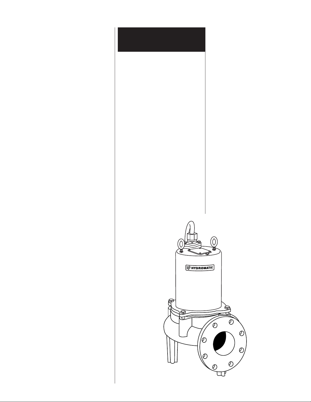
Pump:
The S4S/SB4S submersible
pumps are supplied for 1 and 3
phase and for 200, 230, 460 or
575 volts. Pump is supplied with
15 feet of power cord. Longer
cable lengths can be furnished
but must be specified at time of
order. Power cable is 4 wire with
the green wire for ground. Be sure
green wire is connected to a
ground lug in the control panel
and the control panel must be
connected to a ground rod or
ground wire from supply service.
NOTE: All single phase pumps
require properly sized start
capacitor, start relay and run
capacitor in the panel.
Sump Level Control:
Sump level is controlled by
Hydromatic 3900 mercury switch
level controls. The 3900 level
controls is a metal case
mercury switch sealed in a solid
polyurethane float. The float is
held in position by a weight
attached to the power cord above
the float. The cord supports the
float and is adjusted for height
from the surface.
Typical duplex systems use three
floats: the lowest float turns the
pumps off, the next higher float
starts the lead pump, the next
higher float (override) starts the
lag pump. The pumps alternate
on successive cycles.
Two pumps operate together only
if sump level rises to the third or
override float. The override float
also brings on the second pump in
case of failure of the first pump.
Extra floats with appropriate
controls can be supplied for alarm
functions. Triplex systems use
four floats. The fourth highest
float brings on the second lag
pump. Three pumps operate
together only if sump level rises to
the fourth float (second override).
This float also brings on the third
pump in case of failure of either or
both of the first two pumps.
Alarm Controls:
The alarm float is usually set
above the override level so
the alarm will signal only if the
override level is exceeded.
However, some engineers prefer
to have the alarm float set below
the override level as it is possible
for one pump to fail and the other
pump to operate on the override
level with the sump level never
reaching the alarm level. This is
particularly true in cases of low
inflow capacity.
Electrical Control Panel:
It is recommended that the
Hydromatic control panel be used
with all pumps as proper start
components and pump protection
are furnished.
NOTE: All single phase pumps
require properly sized start
capacitor, start relay, and run
capacitor in the control panel.
IMPORTANT: If Hydromatic
control panel is not used and the
motor fails because of improper
components, the motor guarantee
is void.
2
Hydromatic electrical equipment
is installed in a weatherproof
enclosure. The electrical
equipment includes a main circuit
breaker for each pump, a
magnetic starter with overload
protection for each pump, an
H-O-A switch and run light for
each pump, an electric
alternator and a transformer to
provide appropriate control for
control circuit and alarms.
Overload Heaters:
If a Hydromatic control panel
is not used, on three phase pumps
all three phases must have
overload protection. The overload
should be ambient compensated
class 10. The heater's full load
amps on the pump must be sized
in accordance with the nameplate
amps on the motor housing. The
amp draw on these submersible
motors is slightly higher than
a corresponding horsepower
surface motor, so heaters must be
sized by the nameplate full load
amp rating.
Installing:
Before installing pump in sump,
lay it on side and turn impeller
with fingers. Impeller may be
slightly stuck due to factory test
water, so it must be broken loose
with small bar or screwdriver in
edge of vanes. The impeller
should turn freely.
Clean all trash and sticks from
sump and connect pump to piping.
A check valve must be installed
on each pump. A gate or plug
valve in each pump discharge line
is also recommended. This valve
should be installed on the
discharge side of the check valve
so if necessary to service the
check valve, the line pressure can
be cut off. Single pump systems
are sometimes installed without a
check valve where it is desirable
Pump
Installation
to self-drain the discharge line to
prevent freezing. This can be done
only with short discharge lines.
Otherwise water will return to the
sump and cause short cycling of
the pump.
NEMA 4 Junction Box
(Optional):
If electrical control panel is to be
set remote from the pump sump, a
NEMA 4 junction box should be
used to make power and control
connections. The Hydromatic
NEMA 4 junction box is provided
with compression connectors for
sealing all wires. No sealing
compound is needed to make
connections waterproof.
Wiring diagrams are provided
with the panel for making
connections. An extra set of
diagrams is included so that one
set can be used during installation
when making connections. The
size of any additional wiring from
the pump cord to the panel is
Single phase pumps with
capacitor start circuit must have
the overload protection on the
black pump lead.
NOTE: On single phase pumps
the white, black, and red pump
leads must be connected
properly for the pump to run.
3

Pump
Installation
based on the distance and pump
current. Double check that all
wiring is properly connected and
tight. NOTE: On single phase
pumps the white, black and red
pump wires must be connected
properly to the panel. Only the
proper sequence will work.
Installing 3900 Mercury
Switch Float:
The float cords are supported by a
mounting bracket that is attached
to sump wall or cover or to the
NEMA 4 junction box.
Cord snubbers are used to hold the
cord in place. Float level can be
changed at any time by loosening
the snubber and readjusting
cord length.
In either simplex or duplex
system the lower or turn-off float
is set just above the top of volute
so that the volute will always be
submerged during the pumping
cycle. The second or lead/on float
higher is set at about 24 inches
above the lower turn-off control.
More distance between turn-on
and turn-off controls can be used,
but sewage may become septic
and excessive solids may collect
for the pump to handle. A frequent
pumping cycle is recommended
for best operation.
If an alarm system is used, this
control is usually set about 6
inches above the override control.
Some engineers as described
previously prefer to have the
alarm control set below the
override control.
Making Electrical Connections:
All electrical wiring must be in
accordance with local code, and
only competent electricians
should make the installations. A
set of prints is included for use in
making the installation. All wires
should be checked for grounds
with an ohmmeter or Megger
after the connections are made.
This is important, as one
grounded wire can cause
considerable trouble.
IMPORTANT: If equipment
is not properly wired and
protected as recommended, the
motor guarantee is void.
WIRE SIZE TABLE
FOR REMOTE LOCATION OF CONTROL PANEL; LENGTHS ARE BASED ON A VOLTAGE DROP OF TWO PERCENT
Maximum length in feet from NEMA 4 junction box to control panel. For 3 phase only and for power lines only. All control wires can be = 14–16 or 18 gauge
wire. If power lines are for 460 or 575 volts insulation of control wires must be for this voltage if used in conduit with power lines.
Volts 230 460 575 230 460 575 230 460 575 230 460 575 230 460 575 230 460 575 230 460 575 230 460 575 230 460 575
Wire Motor
Size HP 33355571⁄271⁄271⁄210 10 10 15 15 15 20 20 20 25 25 25 30 30 30 35 35 35
12 110 450 700 90 370 580
10 180 720 1120 140 550 370 90 360 560 50 220 340
8 270 1100 1650 220 900 1400 175 700 1100 105 420 650 320 500 230 360 180 280
6 400 1600 2500 350 1400 2200 220 900 1400 150 600 930 105 420 650 90 370 570 360 560 320 500 230 360
4 370 1500 2300 230 950 1450 175 700 1100 140 550 850 125 500 800 100 400 620 90 360 560
2 370 1500 230 270 1100 1700 220 900 1400 210 820 1250 200 800 1250 150 600 930
*Special Junction Box required for wire sizes larger than #4.
NUMBER OF CONDUCTORS REQUIRED BETWEEN CONTROL PANEL
AND NEMA 4 JUNCTION BOX
System Number of Number of Number of
Type Control Wires Power Lines Ground Wires #8
Simplex 3 3 1
Simplex with Alarm 5 3 1
Duplex 5 6 1
Duplex with Alarm 7 6 1
4
 Loading...