

Pentair HYDROMATIC S4T, HYDROMATIC S8LA, HYDROMATIC S8L, HYDROMATIC S12L Installation And Service Manual
Page 1
MODELS
S4T(X*), S8L(X*),
S8LA(X*) and S12L(X*)
*
Used in Hazardous Locations Class I, Division 1
SUBMERSIBLE
SOLIDS HANDLING PUMP
INSTALLATION AND SERVICE MANUAL
For use with product built with USEM motor.
NOTE! To the installer: Please make sure you provide this manual to the owner of the equip ment or to the responsible
party who maintains the system.
Item # E-03-503 | 320 Frame | Part # 5625-503-1 | © 2014 Pentair Ltd. | 06/20/14
(*Hazardous Location
Motor End)
Page 2

General
Information
Attention:
This manual contains important
information for the safe use of
this product. Read this manual
completely before using this
product and refer to it often
for con tin ued safe product use.
DO NOT THROW AWAY OR
LOSE THIS MAN U AL. Keep
it in a safe place so that you may
refer to it often.
Reasonable care and safe
meth ods should be practiced.
Check local codes and
requirements before installation.
Unpacking Pump:
Remove pump from carton.
When un pack ing unit, check for
con cealed damage. Claims
for damage must be made at
the receiving end through the
delivery carrier. Dam age cannot
be processed from the factory.
WARNING: Before handling
these pumps and controls,
always disconnect the power
first. Do not smoke or use
sparkable electrical devices or
flames in a septic (gaseous) or
possible septic sump.
The Pump
IMPORTANT—Read all the
directions before replacing
any parts.
CALIFORNIA PROPOSITION
65 WARNING:
This product and
related accessories contain
chemicals known to the State of
California to cause cancer, birth
defects or other reproductive
harm.
Pumps Not Operating or
in Storage:
Pumps with carbon ceramic seals
must have impellers manually
rotated (6 revolutions) after
setting non-op er a tion al for 3
2
months or longer and prior to
electrical start-up.
Pumps with tungsten carbide seals
must have impellers manually
rotated (6 revolutions) after
setting non-op er a tion al for
3 weeks or longer and prior to
electrical start-up.
Pump:
The submersible pumps are
supplied for three phase only and
for 460 and 575 volts. Power
cable is supplied with ground. Be
sure ground wire is con nect ed to a
water pipe or ground stake.
Power Cords:
The power cord and heat sensor
seal failure cord are potted into
the con nec tion box cap. The cords
must not be spliced.
NOTE: Each cable has a green
lead. This is the ground wire
and must be grounded properly
per NEC and/or local codes.
Cords should be in spect ed for
abnormal wear and replaced
ac cord ing ly.
Overload Heaters:
If the Hydromatic electrical
panel is not used, start ers with
3 leg overload relay must be
supplied on 3 phase pumps.
Each leg is to have an iden ti cal
heater sized in accordance with
the nameplate amps on the motor
hous ing. The amp draw on these
sub mers ible motors is slightly
higher than a cor re sponding
horsepower sur face motor, so
heat ers must be sized by the
nameplate rating. To adequately
protect these windings with the
appropriate heaters, consult the
factory.
Seal Failure Probes:
All hazardous location
submersible pumps have two
factory installed mois ture
detectors (seal failure probes).
They are in a normally open series
cir cuit, in the seal chamber. Un der
normal operating conditions, the
circuit remains open. If the lower
seal leaks and moisture enters this
cham ber, the moisture would settle
to the bottom of the chamber and
will com plete the circuit between
the mois ture detectors.
This circuit must be connected
to a sensing unit and signaling
device. This is supplied in a
Hydromatic built control panel.
NOTE: Failure to install such a
device negates all war ran ties by
Hydromatic.
Seal Failure:
An electrode probe is installed in
the seal chamber so if any water
enters the chamber through the
first seal the electrode will be
energized and a sig nal will be
transmitted to the sens ing unit at
ground surface causing a red light
to turn on. The electrode probe
is installed in all units but the
sensing unit is supplied at extra
cost and must be ordered.
In operation the seal failure unit
in di cates only that there is some
water in the seal chamber. The
pump will con tin ue to operate
without damage but the seal
should be checked im me di ate ly
after failure is indicated.
The sensing unit is recommended
on all installations as good
insurance against motor failure.
Heat Sensors —
Standard Equipment:
All motors have heat sensor units
em bed ded in the motor winding
to detect excessive heat. The
sensors automatically reset when
mo tor cools to safe tem per a ture.
The sensors are connected in
series with the motor starter coil
so that the starter is tripped if
the heat sensor opens. The motor
starter is equipped with overload
heaters so all normal over loads
are protected by the starter.
Sump Level Control:
Sump level is controlled by
Hydromatic float switch con trols.
Page 3

The float is held in position in
the sump by a weight at tached to
the power cord above the float.
The cord supports the float and
is adjusted for height from the
sur face.
Duplex systems use three
controls: one set at turn-off, one
set at turn-on for one pump, and
one set for turn-on for two pumps.
Pumps alternate op er a tion on each
successive cycle.
Two pumps operate together only
if sump level rises to the third
or over ride control. The override
control also brings on the second
pump in case of failure of the first
pump. The extra float is for alarm.
Triplex systems use four controls:
one set at turn-off, one set at
turn-on for one pump, one set
at turn-on for two pumps, and
one set at turn-on for three
pumps. Pumps alternate each
successive cycle.
Three pumps operate together
only if sump level rises to the
fourth control (second override).
This control also brings on
the third pump in case of failure
of either or both of the first
two pumps.
Alarm Controls:
The alarm level is usually set
above the override level so the
alarm will signal only if the
override level is ex ceed ed.
However, some engineers prefer
to have the alarm level set be low
the override level as it is pos si ble
for one pump to fail and the other
pump to operate on the override
level with the sump level never
reach ing the alarm level. This is
par tic u lar ly true in cases of low
inflow ca pac i ty.
Electrical Control Panel:
Hydromatic electrical equip ment
is installed in a weatherproof
NEMA 3R enclosure. The
electrical equip ment includes
a main circuit breaker for each
pump, a magnetic starter with
overload protection for each
pump, an H-O-A switch and run
light for each pump, an electric
alternator and a transformer to
provide appropriate control for
control and circuit and alarms.
Installation
Instructions
Installing Pump in Sump:
Before installing pump in sump,
lay it on side and turn impeller
manually. Impeller may be
slightly stuck due to factory test
water, so it must be broken loose
with small bar or screwdriver
in edge of vanes. After breaking
loose, the impeller should
turn freely.
Clean all trash and sticks from
sump and connect pump to piping.
A check valve must be installed
on each pump. A gate or plug
valve in each pump discharge
line is also recommended. This
valve should be installed on the
discharge side of the check valve
so if it is necessary to service the
check valve, the line pressure can
be shut off.
NEMA IV Junction Box:
(Optional)
This must be used with 60 and
above horsepower pumps and
with all systems if the electrical
control panel is to be set remote
from the pumps. The Hydromatic
NEMA 4 junction box is provided
with com pres sion connectors
for sealing all wires. No sealing
compound is needed to make
connections wa ter proof.
Wiring diagrams are provided
with the panel for making
connections. The size wire to use
from panel to sump depends on
motor size and distance in feet.
Be sure each wire is checked
so that a wrong connection will
not be made. An ohmmeter or
Megger can be used to check
wire continuity.
Installing Float Switch Controls:
The controls are supported by a
mounting bracket that is attached
to sump wall, cover, or to the
NEMA 4 junction box. Cord
snubbers are used to hold the cord
in place. Control level can be
changed at any time by loosening
the snubber and readjusting
cord height.
In either duplex or triplex
systems, the bottom of the lower
or turn-off control is set just above
the top of volute, so that the volute
will always be submerged during
the pumping cycle. The second,
or turn-on control, is set about
24 inches above the lower turn-off
control.
More distance between turn-on
and turn-off controls can be used,
but sewage may become septic,
and excessive solids may collect
for the pump to handle. A frequent
pumping cycle is recommended
for best operation.
In a duplex system the third or
override control is usually set
about 6 inches above the one pump
turn-on control.
In a triplex system the third or
override control is usually set
24 inches above the one pump
turn-on control, and the fourth
or second override control is
24 inches higher.
If an alarm system is used, this
control is usually set about 6
inches above the override control.
Making Electrical Connections:
All electrical wiring must be in
ac cor dance with local codes, and
only competent electricians should
make the in stal la tions. Complete
wiring diagrams are glued to the
inside cover of the panel. All wires
should be checked for grounds
with an ohmmeter or Megger after
the con nections are made. This is
important, as one grounded wire
can cause considerable trouble.
3
Page 4

Heat Sensors and Seal Failure
Connections:
Be sure heat sensor wires are
con nect ed in series with the
starter coil. Con nec tions are
provided on the terminal strip.
will exist. One leg can be
somewhat higher (5 to 10%)
without causing trouble.
For excessive amp draw on
one leg, the power company
should be consulted.
is required.
Generally, these pumps give
very reliable service, and can
be expected to operate for many
years on normal sewage pumping
without failure.
Pump
Operations
Starting System:
1. Turn H-O-A switch to
Off position and then turn on
main circuit breakers.
2. Open all discharge valves and
allow water to rise in sump.
3. Turn H-O-A switch to Hand
posi tion on one pump and
notice oper ation. If pump is
noisy and vibrates, rotation
is wrong. To change rotation,
interchange any two line
leads to motor 3ø only. Do not
interchange main incoming
lines. If duplex system, check
second pump in same manner.
4. Now set both H-O-A switches
to Auto position and allow
water to rise in sump until
one pump starts. Allow pump
to operate until level drops to
turn-off point.
5. Allow sump level to rise to
start other pump. Notice run
lights on panel. Pumps should
alternate on each successive
cycle of op er a tion.
6. Turn both H-O-A switches
to Off position and allow
sump to fill to the override
control level.
7. Turn both switches to Auto
position and both pumps
should start and operate
together until level drops to
turn-off point.
8. Repeat this operation
cycle several times before
leaving job.
9. Check voltage when pumps
are operating and check the
amp draw of each pump.
Check amps on each wire,
as sometimes a high leg
4
Pump
Maintenance
Field Service on Hydromatic
Hazardous Location Pumps:
If a Hydromatic hazardous location
pump is used in a hazardous
location, or if the pump is still
in war ran ty, the pump must be
returned to the factory for service
or repaired at an authorized
Factory Mutual Hydromatic
service center. Charges will not
be allowed if in war ran ty pump is
not taken to an authorized Factory
Mutual Hydromatic service center.
This will ensure the integrity of
the hazardous location rating of
the pump and com ply with our
warranty re quire ments.
Disconnecting Pump Cords:
If a Hydromatic hazardous location
pump is to be removed from its
loca tion, the pump cords may be
disconnected at control panel (on
sump mounted con trol panels) and
cord as sem bly taken with pump.
CAUTION: If cord openings
from sump to con trol panel are
open, gas es from sump could
enter panel and an explosive
condition could ex ist.
Replacing Cords:
The power cord and heat sensor seal failure cord is potted into the
con nec tion box cap, forming the
cord and cap assembly.
If cords require replacement due to
damage or cords being too short,
cord and cap assembly must be
replaced as a complete assembly
avail able from factory.
Check pump for proper rotation
before re turn ing to normal service.
Motor:
As the motors are oil filled, no
lubrication or other maintenance
Field Service on Motor:
All submersible motors out
of warranty can be serviced in
the field by any reliable motor
service shop. Any pump in
warranty must be returned to the
factory for service or repaired
at an authorized Hydromatic
service center. Charges will not
be allowed if in warranty pump is
not taken to an authorized
Hydromatic
When field service is performed
on a pump, these instructions
should be carefully followed.
Replacing Stator:
1. If stator only is damaged,
it may not be necessary to
completely dismantle pump
as stator and housing can be
lifted from pump without
disturbing seals or bearings.
2. Drain all oil from upper
housing, remove drain plug in
bottom of stator housing and
remove plug in top of housing
to allow air to enter.
3. After chamber is drained,
remove hold-down bolts
and lift off. Use care in
lifting as the seal failure
connecting wire must be
dis con nect ed before housing
is com plete ly removed.
4. Set assembly on bench and
remove connection box.
When box is lifted off,
connection wires to motor will
be exposed. These wires will
probably be burned, but each
wire is tagged with a metal
marker giving wire number.
Cut the wires.
If the leads to the connection
box are burned, a complete
new con nec tion box with new
wire must be used. The wires
service center.
Page 5

are potted in with sealing
compound and a new unit
must be obtained from
the factory.
5. The stator is held in the
housing with a bolted-in
retaining ring and prevented
from rotating by a key.
6. Remove the retaining ring and
socket head cap screw.
7. After ring is removed, turn
housing upright and bump on
hard wood blocks. This should
jar the stator loose and allow
it to drop out.
8. Thoroughly clean housing
before replacing new stator.
Replace stator and make
all wire con nec tions to
the connection box before
replacing housing on pump.
This is important as leads
must be tucked behind the
windings by using hands up
through rotor core.
Do not tape leads as oil will
de te ri o rate the tape and cause
damage to stator and bearings.
9. Check top bearing. If clean
and does not turn rough,
bearings can be reused and it
is not necessary to completely
dismantle pump to change
bearings. If bearings are
damaged with dirt or heat,
they must be re placed.
10. Replace stator housing onto
seal chamber and bolt in place.
Be sure seal failure wire is
connected before housing is
assembled. Be sure back-off
screws have been loosened
so that parts can come metal
to metal. Be sure O-ring seal
has been replaced. If O-ring
is nicked or cut, replace with
new ones. This applies to all
O-rings used in assembly.
11. After all leads are reconnected
in the connection box, make
a high voltage ground test
on each wire. The only wire
that should show ground is
the green power lead and the
ground lead in the auxiliary
control cable.
12. For safety, complete pump
should be air checked under
water for leaks. Lay pump
on side for this oil filling
with oil fill hole upright.
Do not completely fill; leave
oil about 1 inch below plug
hole. Use only Hydromatic
submersible oil in this
chamber. Replace plug; use
Permatex on threads. Install
air valve in top plug opening
of motor housing and charge
housing with about 10 psi
of air. Be sure air is dry.
Do not use air line where
water may be trapped in
the line. Submerge complete
unit under water and check
for leaks.
13. Refill motor chamber with
oil. Use Hydromatic special
submers ible oil. Fill chamber
until oil covers top of the
windings. Leave air space in
the top for expansion. Use
Permatex on plug threads.
Replacing Seals and Bearings:
1. Drain all oil from motor
chamber and seal chamber
as described.
2. Remove motor housing as
described.
3. Remove bolts that hold seal
chamber to pump housing.
Use back-off screws to break
loose. With hardwood block,
tape end of impeller to loosen
from shaft. When free, remove
impeller from shaft.
4. Lift rotating assembly from
pump case and place on bench.
5. Impeller Removal: Hold rotor
and remove bolt and washer
from impeller end of shaft,
then thread bolt back into
shaft. The impeller is keyed
to the shaft, so by using a
screw driv er on opposite sides
behind the im pel ler, apply force
then tap on the end of the bolt
to break impeller loose from
taper shaft. Remove impeller.
6. Remove key and pry on each
side of shoulder of shaft sleeve
to remove. Seal should come
off with sleeve. If sleeve is not
free, leave in place and push off
when seal plate is removed.
7. To remove seal plate take
out socket head flat screws
and using screws in back-off
holes, pry plate loose. This
will also force seal off if not
already re moved.
8. Remove snap ring that holds
upper seal. Pull seal if it
is free. If not free, it can
be forced off when shaft
is removed.
9. Set seal housing assembly in
upright position and bump end
of shaft on hardwood block.
This will push the bearing
from the housing and will
force upper seal from shaft.
10. Use bearing puller to remove
bearings. Replace with new
bearings. Press only on
inner face of bearing when
replacing. Pressing on outer
face can damage the bearing.
IMPORTANT — Do not
use any of the old seal parts.
Replace with all new seals.
11. Thoroughly clean all castings
before replacing seals. One
grain of dirt between the seal
faces can cause failure.
12. Examine all O-Rings for nicks
before reusing.
13. Be sure key is in place in notch
of shaft sleeve to prevent
sleeve from turning.
®
14. Use Locktite
on socket head
locking screw in end of shaft.
15. Before refilling chamber with
oil, air test as described above
and refill both chambers
with oil.
16. Always check all leads with
high voltage or with Megger
for grounds before operating
the pump.
5
Page 6
Pump
Troubleshooting
The following is a list of common
problems and their probable
causes.
Pump will not start.
1. No power to the motor.
Check for blown fuse or open
circuit breaker.
2. Selector switch may be in the
Off position.
3. Control circuit transformer
fuse may be blown.
4. Overload heater on starter
may be tripped. Push to reset.
Pump will not start and
overload heaters trip.
1. Turn off power and check
motor leads with Megger
or ohmmeter for possible
ground.
2. Check resistance of motor
windings. All 3 phases should
show the same reading.
3. If no grounds exist and
the motor windings check
OK, remove pump from sump
and check for clogged or
blocked impeller.
Pump operates with selector
switch in Hand position but will
not operate in Auto position.
1. This indicates trouble in the
level control or the alternator
relay.
2. Check control panel for
trouble.
Pump runs but will not shut off.
Pump does not deliver proper
capacity.
1. Discharge gate valve may
be partially closed or
partially clogged.
2. Check valve may be partially
clogged. Raise the level up
and down to clear.
3. Pump may be running in
wrong direction. Low speed
pumps can operate in reverse
direction without much noise
or vibration.
4. Discharge head may be too
high. Check total head with
gauge when pump is operating.
Total head is discharge gauge
pressure converted to feet
plus vertical height from
water level in sump to center
line of pressure gauge in
discharge line. Gauge should
be installed on pump side of
all valves. Multiply gauge
pressure in pounds by 2.31 to
get head in feet.
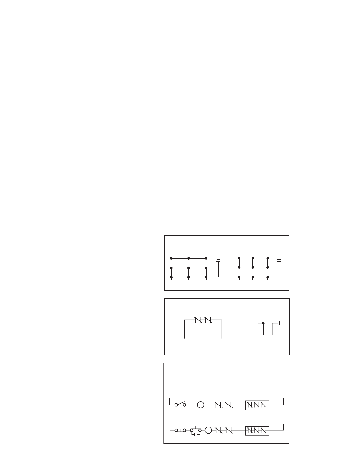
DUAL VOLTAGE
3 PHASE MOTOR WIRING
230V 3ø 460V 3ø
45 6
78 9
12 3
BL
(L1)
HEAT SENSORS AND SEAL FAILURE CONNECTIONS
W
(L2)
HEAT SENSORS
IN MOTOR
WINDINGS
HEAT SENSORS SEAL FAILURE
GREEN GREEN
R
(L3)
FOR ANY VOLTAGE MOTOR
WHITEBLACK
5. If pump has been in service for
some time and capacity falls
off, remove pump and check
for wear or clogged impeller.
Motor stops and then restarts
after short period but overload
heaters in starter do not trip.
1. This indicates heat sensors
in the motor are tripping due
to ex ces sive heat. Impeller
may be partially clogged,
giving a sus tained overload
but not high enough to trip
overload heater switch.
2. Motor may be operating out
of liquid due to a failed level
control.
3. Pump may be operating on
a short cycle due to sump
being too small or from water
returning to sump due to a
leaking check valve.
45 6
78 9
12 3
BL
(L1)
ELECTRODE
R
W
(L3)
(L2)
REDDARK
GREEN
1. Pump may be air locked.
Turn pump off and let set for
several minutes, then restart.
2. Lower float control may be
hung-up in the closed position.
Check in sump to be sure
control is free.
3. Selector switch may be in the
Hand position.
6
COIL
WARNING
COIL
THERMOSTATS
IN SERIES
BLACK
BLACK
THERMOSTATS
IN SERIES
OL OLSTART
WHITE
WHITE
WARRANTY IS VOID IF HEAT SENSORS ARE NOT
CONNECTED AS SHOWN (IN SERIES WITH CONTACTOR OIL)
TWO WIRE CONTROL OFFERING AUTOMATIC RESET
L1
ON-OFF
SWITCH
THREE WIRE CONTROL OFFERING AUTOMATIC RESET
L1
IN CERTAIN APPLICATIONS THE NEC MAY REQUIRE THREE OVERLOAD RELAYS
L2
L2
Page 7
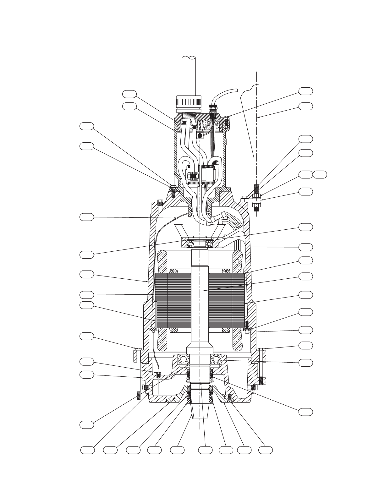
Standard Location
S4T, S8L, S8LA, S12L Motor End Components
18
27
26
3
B3
4
28
31
34
32
29
33
35
30
1
B2
22
19
20
25
23
12
B4
B1
24
9
7
17211116151465
10
8
2
13
7
Page 8

Standard Location
S4T, S8L, S8LA, S12L Motor End Parts List
For use with product built with USEM motor.
Ref.
Part
No.
No.
Description Qty.
1 08565A026 BEARING – BALL (UPPER) 1
2 000650231 BEARING – BALL (LOWER) 1
3 001500191 O-RING 1
4 001500321 O-RING SC 1
5 001500381 O-RING 2
6 001500571 O-RING 1
7 001501081 O-RING (VITON
8 002390351 SCREW – HHC 1/2-13 x 5-1/4 4
9 002390381 SCREW – HHC 1/2-13 x 7-1/4 12
10 005560071 SCREW – CAP (HEX SOC.) 6
11 009750141 RING – RETAINING 1
12 009750101 RING – RETAINING 1
13 037180051 SEAL Carbon Ceramic / Viton
®
) SC 1
®
S 1
Notes: S — Parts in Seal Kit C — Parts in Carbide Seal Kit
Amount of oil required will vary between 8 and 10.5 gal. depending on stator size, fill to above motor windings.
Part
Ref.
Part
No.
14 037180051 SEAL Carbon Ceramic / Viton
037180021 SEAL Tungsten Carbide / Viton
15 023100093 SLEEVE – SHAFT SC 1
16 028550011 KEY – SQUARE 3/8 1
17 029210011 SCREW – CAP (FL. HD SOC) 4
18 19103A052 SCREW – CAP HEX SST 1/2 6
19 060000111 WIRE W/TERMINAL 14 GA. RED 1
20 065790021 KEY – SQUARE 1/4 1
21 073980002 HOUSING – SEAL 1
22 074000042 HOUSING – MOTOR 1
23 074011002 HOUSING – BEARING 1
24 083540003 RING – RETAINING STATOR 1
25 084720025 SEAL FAILURE ASS’Y 1
Part
No.
Description Qty.
®
S 1
®
C Optional
Ref.
Part
No.
26 110650023 SCREEN 3.81 DIA. 1
27 12672A002 CONNECTOR – BUTT 3
28 19101A017 SCREW – CAP HEX SST 3/8 6
29 19109A080 NUT – HEX SST 3/4 4
30 05454A030 WASHER – LOCK 3/4 4
31 151753001 BAIL – LIFTING 1
32 05454A027 WASHER – LOCK 5/8 2
33 151740001 BRACKET – MOUNTING 2
34 19105A033 SCREW – CAP HEX SST 5/8 2
35 000640051
517000687 Seal Kit S
517003687 Carbide Seal Kit C
Part
No.
Description Qty.
SPRING–BEARING 100 hp AND BELOW
SPRING–BEARING 125 hp AND ABOVE
2
3
hp
15–20 200/3/870 141632031 086620121 137690035 141630125
15–20 230/3/870 141630031 086620121 137690065 141630125
15–20 460/3/870 141630031 086620121 137690075 141630125
15–20 575/3/870 141636031 086620121 137690045 141630125
25 200/3/870 141622031 086620091 137690025 141620125
25 230/3/870 141620031 086620091 137690055 141620125
25 460/3/870 141620031 086620091 137690075 141620125
25 575/3/870 141626031 086620091 137690045 141620125
30 200/3/870 141622031 086620091 137690015 141620125
30 230/3/870 141620031 086620091 137690055 141620125
30 460/3/870 141620031 086620091 137690075 141620125
30 575/3/870 141626031 086620091 137690045 141620125
30 200/3/1150 141612031 086620111 137690015 141610125
30 230/3/1150 141610031 086620111 137690055 141610125
30 460/3/1150 141610031 086620111 137690065 141610125
30 575/3/1150 141616031 086620111 137690035 141610125
40 200/3/1150 141612031 086620111 137690015 141610125
40 230/3/1150 141610031 086620111 137690015 141610125
40 460/3/1150 141610031 086620111 137690065 141610125
40 575/3/1150 141616031 086620111 137690035 141610125
50 230/3/1150 141600031 086620041 137690015 141600125
50 460/3/1150 141600031 086620041 137690055 141600125
50 575/3/1150 141606031 086620041 137690035 141600125
60 460/3/1150 141590031 086620031 137690025 141590125
60 575/3/1150 141596031 086620031 137690025 141590125
75 460/3/1150 141590031 086620031 137690015 141590125
75 575/3/1150 141596031 086620031 137690025 141590125
50 460/3/1750 141580031 086620031 137690025 141570125
50 575/3/1750 141586031 086620031 137690035 141570125
60 460/3/1750 141580031 086620031 137690025 141570125
60 575/3/1750 141586031 086620031 137690025 141570125
75 460/3/1750 141580031 086620031 137690015 141570125
75 575/3/1750 141586031 086620031 137690025 141570125
100 460/3/1750 141570031 086620031 137690015 141570125
100 575/3/1750 141576031 086620031 137690015 141570125
125 460/3/1750 141560031 — 137690015 141560125
125 575/3/1750 141566031 — 137690015 141560125
150 460/3/1750 141560031 — 137690085 141560125
150 575/3/1750 141566031 — 137690015 141560125
VOLTAGE/
ph/RPM
B1
STATOR
B2
RING –
SPACER
B3
BOX –
CONNECTION
B4
ROTOR/
SHAFT
8
Page 9

Impeller Parts List / Cord Cap For use with product built with USEM motor.
Description hp Volt/ph Trim Impeller Cord Cap
S4T(X)
1750 RPM
S4T7500M4-4 75 460/3 13 135321092 152760355 152790355
S4T7500M5-4 75 575/3 13 135321092 152760345 152790345
S4T10000M4-4 100 460/3 14 135321052 152760365 152790365
S4T10000M5-4 100 575/3 14 135321052 152760355 152790355
S4T12500M4-4 125 460/3 15 135321012 152760375 152790375
S4T12500M5-4 125 575/3 15 135321012 152760365 152790365
S4T15000M4-4 150 460/3 15.13 135321262 152760375 —
S8L(X)
1750 RPM
S8L7500M4-4 75 460/3 12.12x11.12 25252D559 152760355 152790355
S8L7500M5-4 75 575/3 12.12x11.12 25252D559 152760345 152790345
S8L10000M4-4 100 460/3 13x12 25252D558 152760365 152790365
S8L10000M5-4 100 575/3 13x12 25252D558 152760355 152790355
S8L12500M4-4 125 460/3 13.75x12.75 25252D556 152760375 152790375
S8L12500M5-4 125 275/3 13.75x12.75 25252D556 152760375 —
S8L15000M4-4 150 460/3 15x14 25252D551 152760375 —
S8L15000M5-4 150 575/3 15x14 25252D551 152760365 —
1150 RPM
S8L3000M6-6 30 200/3 13x12 25252D558 152760355 152790355
S8L3000M3-6 30 230/3 13x12 25252D558 152760355 152790355
S8L3000M4-6 30 460/3 13x12 25252D558 152760325 152790325
S8L3000M5-6 30 575/3 13x12 25252D558 152760325 152790325
S8L40000M6-6 40 200/3 14.25x13.25 25252D553 152760365 152790365
S8L40000M3-6 40 230/3 14.25x13.25 25252D553 152760355 152790355
S8L40000M4-6 40 460/3 14.25x13.25 25252D553 152760335 152790335
S8L40000M5-6 40 575/3 14.25x13.25 25252D553 152760325 152790325
S8L50000M3-6 50 230/3 15x15 25252D551 152760365 —
S8L50000M4-6 50 460/3 15x15 25252D551 152760345 152790345
S8L50000M5-6 50 575/3 15x15 25252D551 152760335 152790335
S8L60000M4-6 60 460/3 15x15 25252D550 152760345 152790345
S8L60000M5-6 60 575/3 15x15 25252D550 152760335 152790335
870 RPM
S8L1500M6-8 15 200/3 13.38x12.38 25252D557 152760335 152790335
S8L1500M3-8 15 230/3 13.38x12.38 25252D557 152760325 152790325
S8L1500M4-8 15 460/3 13.38x12.38 25252D557 152760315 152790315
S8L1500M5-8 15 575/3 13.38x12.38 25252D557 152760305 152790305
S8L2000M6-8 20 200/3 14.85x13.85 25252D552 152760335 152790335
S8L2000M3-8 20 230/3 14.85x13.85 25252D552 152760335 152790335
S8L2000M4-8 20 460/3 14.85x13.85 25252D552 152760325 152790325
S8L2000M5-8 20 575/3 14.85x13.85 25252D552 152760315 152790315
S8L2500M6-8 25 200/3 15x14 25252D550 152760345 152790345
S8L2500M3-8 25 230/3 15x14 25252D550 152760345 152790345
S8L2500M4-8 25 460/3 15x14 25252D550 152760325 152790325
S8L2500M5-8 25 575/3 15x14 25252D550 152760325 152790325
S8L3000M4-8 30 460/3 15x14 25252D550 152760325 —
Haz. Loc.
Cord Cap
Description hp Volt/ph Trim Impeller Cord Cap
S8LA(X)
1750 RPM
S8LA7500M4-4 75 460/3 13 135320052 152760355 152790355
S8LA7500M5-4 75 575/3 13 135320052 152760345 152790345
S8LA10000M4-4 100 460/3 14 135320012 152760365 152790365
S8LA10000M5-4 100 575/3 14 135320012 152760355 152790355
S8LA12500M4-4 125 460/3 15 135320092 152760375 152790375
S8LA12500M5-4 125 575/3 15 135320092 152760365 152790365
S12L(X)
1750 RPM
S12L7500M4-4 75 460/3 11x10 25456E562 152760355 152790355
S12L7500M5-4 75 575/3 11x10 25456E562 152760345 152790345
S12L10000M4-4 100 460/3 11.5x11 25456E563 152760365 152790365
S12L10000M5-4 100 575/3 11.5x11 25456E563 152760355 152790355
S12L12500M4-4 125 460/3 12.5x11 25456E564 152760375 152790375
S12L12500M5-4 125 275/3 12.5x11 25456E564 152760365 —
S12L15000M4-4 150 460/3 13x11 25456E565 152760375 —
S12L15000M5-4 150 575/3 13x11 25456E565 152760365 —
1150 RPM
S12L40000M3-6 40 230/3 12.31 25456E560 152760355 152790355
S12L40000M4-6 40 460/3 12.31 25456E560 152760335 152790335
S12L40000M5-6 40 575/3 12.31 25456E560 152760325 152790325
S12L50000M3-6 50 230/3 13.06 25456E560 152760365 —
S12L50000M4-6 50 460/3 13.06 25456E555 152760345 152790345
S12L50000M5-6 50 575/3 13.06 25456E555 152760335 152790335
S12L60000M4-6 60 460/3 13.63 25456E553 152760345 152790345
S12L60000M5-6 60 575/3 13.63 25456E553 152760335 152790335
S12L75000M4-6 75 460/3 14 25456E552 152760355 152790355
S12L75000M5-6 75 575/3 14 25456E552 152760345 152790345
870 RPM
S12L1500M6-8 15 200/3 12.25 25456E561 152760335 152790335
S12L1500M3-8 15 230/3 12.25 25456E561 152760325 152790325
S12L1500M4-8 15 460/3 12.25 25456E561 152760315 152790315
S12L1500M5-8 15 575/3 12.25 25456E561 152760305 152790305
S12L2000M6-8 20 200/3 13 25456E556 152760335 152790335
S12L2000M3-8 20 230/3 13 25456E556 152760335 152790335
S12L2000M4-8 20 460/3 13 25456E556 152760325 152790325
S12L2000M5-8 20 575/3 13 25456E556 152760315 152790315
S12L2500M6-8 25 200/3 13.5 25456E554 152760345 152790345
S12L2500M3-8 25 230/3 13.5 25456E554 152760345 152790345
S12L2500M4-8 25 460/3 13.5 25456E554 152760325 152790325
S12L2500M5-8 25 575/3 13.5 25456E554 152760325 152790325
S12L3000M6-8 30 200/3 14 25456E552 152760355 152790355
S12L3000M3-8 30 230/3 14 25456E552 152760345 152790345
S12L3000M4-8 30 460/3 14 25456E552 152760325 152790325
S12L3000M5-8 30 575/3 14 25456E552 152760325 152790325
Haz. Loc.
Cord Cap
Wet End Components
S4T(X)
Item
Number
D1 SCREW – CAP CHARTED 048200111 (4) 001780011 (4) — 07597A021 (4)
D2 WASHER – IMPELLER HOLD 019450013 1 1 1 1
D3 SCREW – CAP 038790021 1 1 1 1
D4 CASE – VOLUTE CHARTED 136880002 073942002 25457F200 073940002
D5 RING – WEAR CHARTED 136950003 083450002 25458D000 135350003
D6 RING – CLAMP CHARTED — — — 135360003
D7 BELL – SUCTION 105871002 — — 1 —
D8 STAND – PUMP S12L 106270005 — — 1 —
D9 SCREW – CAP 19106A017 — — 8 —
D10 SCREW – CAP SKT HD 1/4-20 06106A045 — — 4 —
D11 SCREW – CAP SST 19103A043 — — 8 —
Description Part Number S4T(X) S8L(X) S12L(X) S8LA(X)
S8L(X)
S8LA(X)
S12L(X)
9
Page 10

Hazardous Location
PROBE TEST RESISTOR
ON HAZARDOUS LOCATION ONLY
–
PROBE TEST RESISTOR
ON HAZARDOUS LOCATION ONLY
PROBE TEST RESISTOR
ON HAZARDOUS LOCATION ONLY
PROBE TEST RESISTOR
ON HAZARDOUS LOCATION ONLY
––
–
PROBE TEST RESISTOR
ON HAZARDOUS LOCATION ONLY
––
–
S4TX, S8LX, S8LAX, S12LX Motor End Components
B5
B3
17
23
B1
24
14
3
26
13
6
29
B4
1
18
B2
19
10
2
9
8
12
25
27
20
5
22 1542811 21 16
7
Wiring Diagrams
10
Page 11

Hazardous Location
S4TX, S8LX, S8LAX, S12LX Motor End Parts List
For use with product built with USEM motor.
Ref.
Part
No.
No.
Description Qty.
1 08565A026 BEARING–BALL (UPPER) 1
2 000650231 BEARING–BALL (LOWER) 1
3 001500191 O-RING 6.734 I.D. 1
4 001500211 O-RING 7.734 I.D. 1
5 001500381 O-RING 14.984 I.D. 2
6 001500421 O-RING 5.359 I.D. 1
7 001501081 O-RING 2.484 I.D. 1
8 002390241 SCREW–HHC 1/2-13 4
9 002390261 SCREW–HHC 1/2-13 12
10 005560071 SCREW–HEX SOC. 3/8 x 1-1/2 6
11 028550011 KEY–SQUARE 3/8 1
Note: Amount of oil required will vary between 8 and 10-1/2 gals. depending on stator size, fill to above motor windings.
4-Pole 1750 RPM
Part
4-Pole 1750RPM
Item
Description
B1 Stator 141580031 141586031 141570031 141576031 141560031 141566031
B2 Rotor/Shaft Assembly 141580145 141580145 141580145 141580145 141560145 141560145
B3 Box–Connection 114110105 114110045 114110105 114110105 114110105 114110105
B5 Cord Cap 152790355 152790345 152790365 152790355 152790375 152790365
75hp
460/3/1750
75hp
575/3/1750
100hp
460/3/1750
Ref.
Part
No.
12 009750141 RING–RETAINING 1
13 011240021 NUT–HEX 5/8 (JAM) 2
14 065790021 KEY–SQUARE .250 SQ. x 3.88 1
15 023100103 SLEEVE–SHAFT SEAL 1
16 029210011 SCREW–CAP 1/2-13 x 1-1/4 4
17 19103A043 SCREW–CAP 1/2-13 x 1-1/2 6
18 074000042 HOUSING–MOTOR 1
19 083540003 RING–RETAINING STATOR 1
20 107460002
107461002
21 107560002 PLATE-SEAL 1
100hp
575/3/1750
Part
No.
Description Qty.
HOUSING–BEARING 100 hp AND BELOW
HOUSING–BEARING 125 hp AND ABOVE
125hp
460/3/1750
125hp
575/3/1750
Ref.
Part
No.
22 107820013 RING–LABYRINTH 1
23 108980001 CONNECTOR–BUTT 4
24 109000045 SEAL SENSOR ASS’Y 1
25 109010001 PROBE–SEAL FAILURE 1
26 19101A017 SCREW–CAP 3/8-16 x 1-1/4 6
27 037180051 SEAL Carbon Ceramic / Viton
037180021 SEAL Tungsten Carbide / Viton
28 037180051 SEAL Carbon Ceramic / Viton
1
1
037180021 SEAL Tungsten Carbide / Viton
29 000640051
Part
No.
Description Qty.
SPRING–BEARING 100 hp AND BELOW
SPRING–BEARING 125 hp AND ABOVE
®
®
®
®
1
Optional
1
Optional
2
3
6-Pole 1150 RPM
6-Pole 1150RPM
Item
Description
B1 Stator 141612031 141610031 141610031 141616031 141612031 141610031 141610031 141616031 141600031 141606031 141590031 141596031 141590031 141596031
B2 Rotor/Shaft Assembly 141610145 141610145 141610145 141610145 141610145 141610145 141610145 141610145 141600145 141600145 141590145 141590145 141590145 141590145
B3 Box–Connection 114110105 114110055 114110035 114110025 114110105 114110105 114110035 114110025 114110055 114110025 114110045 114110045 114110105 114110045
B4 Ring–Spacer 086620101 086620101 086620101 086620101 086620101 086620101 086620101 086620101 086620071 086620071 — — — —
B5 Cord Cap 152790355 152790355 152790325 152790325 152790365 152790355 152790335 152790325 152790345 152790335 152790345 152790335 152790355 152790345
30hp
200/3/1150
30hp
230/3/1150
30hp
460/3/1150
30hp
575/3/1150
40hp
200/3/1150
40hp
230/3/1150
40hp
460/3/1150
40hp
575/3/1150
50hp
460/3/1150
50hp
575/3/1150
60hp
460/3/1150
60hp
575/3/1150
75hp
460/3/1150
575/3/1150
8-Pole 870 RPM
8-Pole 870RPM
Item
Description
B1 Stator 141632031 141630031 141630031 141636031 141632031 141630031 141630031 141636031 141622031 141620031 141620031 141626031
B2 Rotor/Shaft Assembly 141630145 141630145 141630145 141630145 141630145 141630145 141630145 141630145 141620145 141620145 141620145 141620145
B3 Box–Connection 114110025 114110035 114110015 114110005 114110025 114110035 114110015 114110005 114110045 114110055 114110015 114110005
B4 Ring–Spacer 086620091 086620091 086620091 086620091 086620091 086620091 086620091 086620091 086620021 086620021 086620021 086620021
B5 Cord Cap 152790335 152790325 152790315 152790305 152790335 152790335 152790325 152790315 152790345 152790345 152790325 152790325
8-Pole 870RPM
Item
Description
B1 Stator 141622031 141620031 141620031 141626031
B2 Rotor/Shaft Assembly 141620145 141620145 141620145 141620145
B3 Box–Connection 114110105 114110055 114110015 114110005
B4 Ring–Spacer 086620021 086620021 086620021 086620021
B5 Cord Cap 152790355 152790345 152790325 152790325
15hp
200/3/870
30hp
200/3/870
15hp
230/3/870
30hp
230/3/870
15hp
460/3/870
30hp
460/3/870
15hp
575/3/870
30hp
575/3/870
20hp
200/3/870
20hp
230/3/870
20hp
460/3/870
20hp
575/3/870
25hp
200/3/870
25hp
230/3/870
25hp
460/3/870
25hp
575/3/870
75hp
11
Page 12

STANDARD LIMITED WARRANTY
Pentair Hydromatic® warrants its products against defects in material and workmanship for a period of 12 months
from the date of shipment from Pentair Hydromatic or 18 months from the manufacturing date, whichever
occurs first – provided that such products are used in compliance with the requirements of the Pentair Hydromatic
catalog and technical manuals for use in pumping raw sewage, municipal wastewater or similar, abrasive-free,
noncorrosive liquids.
During the warranty period and subject to the conditions set forth, Pentair Hydromatic, at its discretion, will repair
or replace to the original user, the parts that prove defective in materials and workmanship. Pentair Hydromatic
reserves the right to change or improve its products or any portions thereof without being obligated to provide such
a change or improvement for prior sold and/or shipped units.
Start-up reports and electrical schematics may be required to support warranty claims. Submit at the time of start up
through the Pentair Hydromatic website: http://forms.pentairliterature.com/startupform/startupform.asp?type=h.
Warranty is effective only if Pentair Hydromatic authorized control panels are used. All seal fail and heat sensing
devices must be hooked up, functional and monitored or this warranty will be void. Pentair Hydromatic will cover
only the lower seal and labor thereof for all dual seal pumps. Under no circumstance will Pentair Hydromatic be
responsible for the cost of field labor, travel expenses, rented equipment, removal/reinstallation costs or freight
expenses to and from the factory or an authorized Pentair Hydromatic service facility.
This limited warranty will not apply: (a) to defects or malfunctions resulting from failure to properly install, operate or
maintain the unit in accordance with the printed instructions provided; (b) to failures resulting from abuse, accident
or negligence; (c) to normal maintenance services and parts used in connection with such service; (d) to units that
are not installed in accordance with applicable local codes, ordinances and good trade practices; (e) if the unit is
moved from its original installation location; (f) if unit is used for purposes other than for what it is designed and
manufactured; (g) to any unit that has been repaired or altered by anyone other than Pentair Hydromatic or an
authorized Pentair Hydromatic service provider; (h) to any unit that has been repaired using non factory specified/
OEM parts.
Warranty Exclusions: PENTAIR HYDROMATIC MAKES NO EXPRESS OR IMPLIED WARRANTIES THAT EXTEND
BEYOND THE DESCRIPTION ON THE FACE HEREOF. PENTAIR HYDROMATIC SPECIFICALLY DISCLAIMS THE
IMPLIED WARRANTIES OF MERCHANTABILITY AND FITNESS FOR ANY PARTICULAR PURPOSE.
Liability Limitation: IN NO EVENT SHALL PENTAIR HYDROMATIC BE LIABLE OR RESPONSIBLE FOR
CONSEQUENTIAL, INCIDENTAL OR SPECIAL DAMAGES RESULTING FROM OR RELATED IN ANY MANNER TO
ANY PENTAIR HYDROMATIC PRODUCT OR PARTS THEREOF. PERSONAL INJURY AND/OR PROPERTY DAMAGE
MAY RESULT FROM IMPROPER INSTALLATION. PENTAIR HYDROMATIC DISCLAIMS ALL LIABILITY, INCLUDING
LIABILITY UNDER THIS WARRANTY, FOR IMPROPER INSTALLATION. PENTAIR HYDROMATIC RECOMMENDS
INSTALLATION BY PROFESSIONALS.
Some states do not permit some or all of the above warranty limitations or the exclusion or limitation of incidental or
consequential damages and therefore such limitations may not apply to you. No warranties or representations at any
time made by any representatives of Pentair Hydromatic shall vary or expand the provision hereof.
740 EAST 9TH STREET 490 PINEBUSH ROAD, UNIT #4
ASHLAND, OHIO, USA 44805 CAMBRIDGE, ONTARIO, CANADA N1T 0A5
419-289-1144 800-363-PUMP
WWW.HYDROMATIC.COM
Warranty Rev. 12/13
Page 13

S8L
S4T
MODELS S4T, S8L,
S8LA and S12L
SUBMERSIBLE
SOLIDS HANDLING PUMPS
INSTALLATION AND SERVICE MANUAL
For use with product built with GE® motor.
NOTE! To the installer: Please make sure you provide this manual to the owner of the equip ment or to the responsible
party who maintains the system.
Item # E-03-342 | Part # 5625-342-1 | © 2012 Pentair Pump Group, Inc. | 10/25/12
Page 14

General
Information
Thank you for purchasing your
Hydromatic
ensure years of trouble-free
op er a tion, please read the
fol low ing manual carefully.
Before Operation:
Read the following in structions care ful ly. Reasonable care
and safe meth ods should be
practiced. Check local codes and
requirements before installation.
Attention:
This manual contains important
information for the safe use of
this product. Read this manual
completely before using this
product and refer to it often
for con tin ued safe product use.
DO NOT THROW AWAY OR
LOSE THIS MAN U AL. Keep
it in a safe place so that you may
refer to it often.
Unpacking Pump:
Remove pump from carton.
When un pack ing unit, check for
con cealed damage. Claims
for damage must be made at
the receiving end through the
delivery carrier. Dam age cannot
be processed from the factory.
WARNING: Before handling
these pumps and controls,
always disconnect the power
first. Do not smoke or use
sparkable electrical devices or
flames in a septic (gaseous) or
possible septic sump.
2
®
pump. To help
CALIFORNIA PROPOSITION
65 WARNING:
This product and
related accessories contain
chemicals known to the State of
California to cause cancer, birth
defects or other reproductive
harm.
Pumps Not Operating or
in Storage:
Pumps with carbon ceramic seals
must have impellers manually
rotated (6 revolutions) after
setting non-op er a tion al for 3
months or longer and prior to
electrical start-up.
Pumps with tungsten carbide seals
must have impellers manually
rotated (6 revolutions) after
setting non-op er a tion al for
3 weeks or longer and prior to
electrical start-up.
Pump:
The submersible pumps are
supplied for three phase only and
for 230, 460 or 575 volts. Power
cable is supplied with ground. Be
sure ground wire is con nect ed to a
water pipe or ground stake.
Seal Failure:
An electrode probe is installed in
the seal chamber so if any water
enters the chamber through the
first seal the electrode will be
energized and a sig nal will be
transmitted to the sens ing unit at
ground surface causing a red light
to turn on. The electrode probe
is installed in all units but the
sensing unit is supplied at extra
cost and must be ordered.
In operation the seal failure unit
in di cates only that there is some
water in the seal chamber. The
pump will con tin ue to operate
without damage but the seal
should be checked im me di ate ly
after failure is indicated.
The sensing unit is recommended
on all installations as good
insurance against motor failure.
Heat Sensors—
Standard Equipment:
All motors have heat sensor units
em bed ded in the motor winding
to detect excessive heat. The heat
sen sors are set to trip at 105°C,
so will not op er ate unless
dangerous heat occurs. The
sensors automatically reset when
mo tor cools to safe tem per a ture.
The sensors are connected in
series with the motor starter coil
so that the starter is tripped if heat
sensor opens. The motor starter is
equipped with overload heaters so
all normal over loads are protected
by the starter.
Sump Level Control:
Sump level is controlled by
Hydromatic float switch con trols.
The float is held in position in
the sump by a weight at tached to
the power cord above the float.
The cord supports the float
and is adjusted for height from
the sur face.
Duplex systems use three
controls: one set at turn-off, one
set at turn-on for one pump, and
one set for turn-on for two pumps.
Pumps alternate op er a tion on each
successive cycle.
Two pumps operate together only
if sump level rises to the third
or over ride control. The override
control also brings on the second
pump in case of failure of the first
pump. The extra float is for alarm.
Triplex systems use four controls:
one set at turn-off, one set at
turn-on for one pump, one set
at turn-on for two pumps, and
one set at turn-on for three
pumps. Pumps alternate each
successive cycle.
Page 15

Three pumps operate together
only if sump level rises to the
fourth control (second override).
This control also brings on
the third pump in case of failure
of either or both of the first
two pumps.
Alarm Controls:
The alarm level is usually set
above the override level so the
alarm will signal only if the
override level is ex ceed ed.
However, some engineers prefer
to have the alarm level set be low
the override level as it is pos si ble
for one pump to fail and the other
pump to operate on the override
level with the sump level never
reach ing the alarm level. This is
par tic u lar ly true in cases of low
inflow ca pac i ty.
Electrical Control Panel:
Hydromatic electrical equip ment
is installed in a weatherproof
NEMA 3R enclosure. The
electrical equip ment includes
a main circuit breaker for each
pump, a magnetic starter with
overload protection for each
pump, an H-O-A switch and run
light for each pump, an electric
alternator and a transformer to
provide appropriate control for
control and circuit and alarms.
Installation
Instructions
Installing Pump in Sump:
Before installing pump in sump,
lay it on side and turn impeller
manually. Impeller may be
slightly stuck due to factory test
water, so it must be broken loose
with small bar or screwdriver
in edge of vanes. After breaking loose, the impeller should
turn freely.
Clean all trash and sticks from
sump and connect pump to piping.
A check valve must be installed
on each pump. A gate or plug
valve in each pump discharge
line is also recommended. This
valve should be installed on the
discharge side of the check valve
so if it is necessary to service the
check valve, the line pressure can
be shut off.
NEMA IV Junction Box:
(optional)
This must be used with 60 and
above horsepower pumps and
with all systems if the electrical
control panel is to be set remote
from the pumps. The Hydromatic
NEMA 4 junction box is provided
with com pres sion connectors
for sealing all wires. No sealing
compound is needed to make
connections wa ter proof.
Wiring diagrams are provided
with the panel for making
connections. The size wire to use
from panel to sump depends on
motor size and distance in feet.
Be sure each wire is checked so
that a wrong connection will not
be made. An ohmmeter or
Megger can be used to check
wire continuity.
Installing Float Switch
Controls:
The controls are supported by a
mounting bracket that is attached
to sump wall, cover, or to the
NEMA 4 junction box. Cord
snubbers are used to hold the cord
in place. Control level can be
changed at any time by loosening
the snubber and readjusting
cord height.
In either duplex or triplex
systems, the bottom of the lower
or turn-off control is set just above
the top of volute, so that the
volute will always be submerged
during the pumping cycle. The
second, or turn-on control, is set
about 24 inches above the lower
turn-off control.
More distance between turn-on
and turn-off controls can be used,
but sewage may become septic,
and excessive solids may collect
for the pump to handle. A frequent
pumping cycle is recommended
for best operation.
In a duplex system the third or
override control is usually set
about 6 inches above the one
pump turn-on control.
In a triplex system the third or
override control is usually set
24 inches above the one pump
turn-on control, and the fourth
or second override control is 24
inches higher.
If an alarm system is used, this
control is usually set about 6
inches above the override control.
Making Electrical Connections:
All electrical wiring must be in
ac cor dance with local codes, and
only competent electricians should
make the in stal la tions. Complete
wiring diagrams are glued to the
inside cover of the panel. All wires
should be checked for grounds
with an ohmmeter or Megger after
the con nec tions are made. This is
important, as one grounded wire
can cause considerable trouble.
IMPORTANT: If equipment is
not properly wired and protected
as rec om mend ed, the warranty
is void.
3
Page 16

Installation
Instructions
Heat Sensors and Seal Failure
Connections:
Be sure heat sensor wires are
con nect ed in series with the
starter coil. Con nec tions are
provided on the terminal strip.
Pump
Operations
Starting System:
1. Turn H-O-A switch to
Off position and then turn on
main circuit breakers.
2. Open all discharge valves and
allow water to rise in sump.
3. Turn H-O-A switch to Hand
posi tion on one pump and
notice oper ation. If pump is
noisy and vibrates, rotation
is wrong. To change rotation,
interchange any two line leads
to motor 3ø only. Do not
interchange main incoming
lines. If duplex system, check
second pump in same manner.
4. Now set both H-O-A switches
to Auto position and allow
water to rise in sump until
one pump starts. Allow pump
to operate until level drops to
turn-off point.
5. Allow sump level to rise to
start other pump. Notice run
lights on panel. Pumps should
alternate on each successive
cycle of op er a tion.
6. Turn both H-O-A switches
to Off position and allow
sump to fill to the override
control level.
7. Turn both switches to Auto
position and both pumps should
start and operate together until
level drops to turn-off point.
8. Repeat this operation cycle
several times before leaving
the job.
9. Check voltage when pumps
are operating and check the
amp draw of each pump.
Check amps on each wire,
as sometimes a high leg
will exist. One leg can be
somewhat higher (5 to 10%)
without causing trouble. For
excessive amp draw on one
leg, the power company should
be consulted.
As the motors are oil filled, no
lubrication or other maintenance
is required.
Generally, these pumps give
very reliable service, and can
be expected to operate for many
years on normal sewage pumping
without failure.
Field Service on Motor:
Submersible motors out of
warranty can be serviced in
the field by any reliable motor
service shop. Any pump in
warranty must be returned to the
factory for service or repaired
at an authorized Hydromatic
service center. Charges will not be
allowed if in warranty pump is not
WARRANTY IS VOID IF HEAT SENSORS ARE NOT
CONNECTED AS SHOWN (IN SERIES WITH CONTACTOR OIL)
TWO WIRE CONTROL OFFERING AUTOMATIC RESET
L1
ON-OFF
SWITCH
WARNING
COIL
taken to an authorized
Hydromatic
service center.
When field service is performed
on a pump, these instructions
should be carefully followed.
Replacing Stator:
1. If stator only is damaged,
it may not be necessary to
completely dismantle pump
as stator and housing can be
lifted from pump without
disturbing seals or bearings.
2. Drain all oil from upper
housing, remove drain plug in
bottom of stator housing and
remove plug in top of housing
to allow air to enter.
3. After chamber is drained,
remove hold-down bolts
and lift off. Use care in
lifting as the seal failure
connecting wire must be
dis con nect ed before housing
is com plete ly removed.
4. Set assembly on bench and
remove connection box. When
box is lifted off, connection
wires to motor will be exposed.
These wires will probably be
burned, but each wire is tagged
with a metal marker giving
wire number. Cut the wires.
If the leads to the connection
box are burned, a complete
new con nec tion box with new
wire must be used. The wires
are potted in with sealing
BLACK
THERMOSTATS
IN SERIES
L2
WHITE
4
THREE WIRE CONTROL OFFERING AUTOMATIC RESET
L1
IN CERTAIN APPLICATIONS THE NEC MAY REQUIRE THREE OVERLOAD RELAYS
COIL
OL OLSTART
BLACK
THERMOSTATS
IN SERIES
WHITE
L2
Page 17

compound and a new unit
must be obtained from
the factory.
5. The stator is held in the
housing with a bolted-in
retaining ring and prevented
from rotating by a key.
6. Remove the retaining ring and
socket head cap screw.
7. After ring is removed, turn
housing upright and bump on
hard wood blocks. This should
jar the stator loose and allow it
to drop out.
8. Thoroughly clean housing
before replacing new stator.
Replace stator and make all
wire con nec tions to connection
box before replacing housing
on pump. This is important as
leads must be tucked behind
the windings by using hands
up through rotor core.
Do not tape leads as oil will
de te ri o rate the tape and cause
damage to stator and bearings.
9. Check top bearing. If clean and
does not turn rough, bearings
can be reused and it is not
necessary to completely
dismantle pump to change
bearings. If bearings are
damaged with dirt or heat,
they must be re placed.
10.Replace stator housing onto
seal chamber and bolt in place.
Be sure seal failure wire is
connected before housing is
assembled. Be sure back-off
screws have been loosened
so that parts can come metal
to metal. Be sure O-ring seal
has been replaced. If O-ring
is nicked or cut, replace with
new ones. This applies to all
O-rings used in assembly.
11.After all leads are reconnected
in the connection box, make
a high voltage ground test
on each wire. The only wire
that should show ground is
the green power lead and the
ground lead in the auxiliary
control cable.
12.For safety, complete pump
should be air checked under
water for leaks. Lay pump on
side for this oil filling with
oil fill hole upright. Do not
completely fill; leave oil about
1 inch below plug hole. Use
only Hydromatic submersible
oil in this chamber. Replace
plug; use Permatex on threads.
Install air valve in top plug
opening of motor housing and
charge housing with about
10 psi of air. Be sure air is dry.
Do not use air line where water
may be trapped in the line.
Submerge complete unit under
water and check for leaks.
13.Refill motor chamber with
oil. Use Hydromatic special
sub mers ible oil. Fill chamber
until oil covers top of the
windings. Leave air space in
the top for expansion. Use
Permatex on plug threads.
Replacing Seals and Bearings:
1. Drain all oil from motor
chamber and seal chamber
as described.
2. Remove motor housing
as described.
3. Remove bolts that hold seal
chamber to pump housing.
Use back-off screws to break
loose. With hardwood block,
tape end of impeller to loosen
from shaft. When free, remove
impeller from shaft.
4. Lift rotating assembly from
pump case and place on bench.
5. Impeller Removal: Hold rotor
and remove bolt and washer
from impeller end of shaft,
then thread bolt back into shaft.
The impeller is keyed to the
shaft, so by using a screwdriver on opposite sides behind the
im pel ler, apply force then tap
on the end of the bolt to break
impeller loose from taper shaft.
Remove impeller.
6. Remove key and pry on each
side of shoulder of shaft sleeve
to remove. Seal should come
off with sleeve. If sleeve is not
free, leave in place and push
off when seal plate is removed.
7. To remove seal plate take
out socket head flat screws
and using screws in back-off
holes pry plate loose. This
will also force seal off if not
already re moved.
8. Remove snap ring that holds
upper seal. Pull seal if it is free.
If not free, it can be forced off
when shaft is removed.
9. Set seal housing assembly in
upright position and bump end
of shaft on hardwood block.
This will push the bearing
from the housing and will force
upper seal from shaft.
10.Use bearing puller to remove
bearings. Replace with new
bearings. Press only on the
inner face of bearing when
replacing. Pressing on outer
face can damage the bearing.
IMPORTANT—Do not use any
of the old seal parts. Replace
with all new seals.
11.Thoroughly clean all castings
before replacing seals. One
grain of dirt between the seal
faces can cause failure.
12.Examine all O-Rings for nicks
before reusing.
13.Be sure key is in place in
notch of shaft sleeve to prevent
sleeve from turning.
14.Use Locktite
®
on socket head
locking screw in end of shaft.
5
Page 18

15.Before refilling chamber
with oil, air test as described
above and refill both chambers
with oil.
16.Always check all leads with
high voltage or with Megger
for grounds before operating
the pump.
Pump
Troubleshooting
Below is a list of common
problems and the probable causes:
Pump will not start.
Pump operates with selector
switch in Hand position but will
not operate in Auto position.
1. This indicates trouble in
the level control or the
alternator relay.
2. Check control panel for trouble.
Pump runs but will not shut off.
1. Pump may be air locked.
Turn pump off and let set for
several minutes, then restart.
2. Lower float control may be
hung-up in the closed position.
Check in sump to be sure
control is free.
3. Selector switch may be in the
Hand position.
Motor stops and then restarts
after short period but overload
heaters in starter do not trip.
1. This indicates heat sensors
in the motor are tripping due
to ex ces sive heat. Impeller
may be partially clogged
giving a sus tained overload
but not high enough to trip
overload heater switch.
2. Motor may be operating
out of liquid due to a failed
level control.
3. Pump may be operating on
a short cycle due to sump
being too small or from water
returning to sump due to a
leaking check valve.
1. No power to the motor.
Check for blown fuse or open
circuit breaker.
2. Selector switch may be in the
Off position.
3. Control circuit transformer
fuse may be blown.
4. Overload heater on starter may
be tripped. Push to reset.
Pump will not start and
overload heaters trip.
1. Turn off power and check
motor leads with Megger or
ohmmeter for possible ground.
2. Check resistance of motor
windings. All 3 phases should
show the same reading.
3. If no grounds exist and
the motor windings check
OK, remove pump from sump
and check for clogged or
blocked impeller.
Pump does not deliver proper
capacity.
1. Discharge gate valve may
be partially closed or
partially clogged.
2. Check valve may be partially
clogged. Raise level up and
down to clear.
3. Pump may be running in
wrong direction. Low speed
pumps can operate in reverse
direction without much noise
or vibration.
4. Discharge head may be
too high. Check total head
with gauge when pump is
operating. Total head is
discharge gauge pressure
converted to feet plus vertical
height from water level in
sump to center line of pressure
gauge in discharge line. Gauge
should be installed on pump
side of all valves. Multiply
gauge pressure in pounds by
2.31 to get head in feet.
6
5. If pump has been in service for
some time and capacity falls
off, remove pump and check
for wear or clogged impeller.
Page 19

S4T Parts List
For use with product built with GE® motor.
Ref. Part Part
No. No. Description Qty.
1 00238-006-1 Capscrew 6
2 00087-004-1 1/8” Pipe Plug 1
3 00282-001-1 Wire Connector 3
4 01664-002-1 1/8” Pipe Plug Brz 1
5 RTF Cord Assy. 1
6 02498-008-1 Split Bolt Connector 3
7 06000-011-1 Seal Failure Conn Wire 1
8 03718-005-1 Up per Seal S 1
9 03718-005-1 Lower Seal, ceramic (std) S 1
03718-002-1 Lower Seal, carbide (opt) C 1
10 08472-002-5 Seal Failure Probe 1
11 00150-038-1 O-Ring SC 2
12 00924-003-1 1/2 Pipe Plug, brz 2
13 11065-002-3 Bearing Plate Screen 1
14 00239-035-1 1/2 Hex Hd Capscrew 12
15 07398-000-2 Seal Housing 1
16 02310-004-3 Seal Sleeve SC 1
17 00150-108-1 O-Ring SC 1
18 03879-002-1 Soc Hd Capscrew 1
19 00829-009-1 Machine Screw 4
20 13695-000-3 Wear Ring 1
21 13532-101-2 Impeller 15” Dia 1
13532-105-2 Impeller 14” Dia 1
13532-109-2 Impeller 13” Dia 1
22 01945-001-3 Impeller Washer 1
23 13688-000-2 Volute 1
24 02855-001-1 Impeller Key 1
25 02921-001-1 Flt Hd Soc Capscrew 4
26 07401-000-2 Bearing Housing 1
27 00150-057-1 O-Ring SC 1
28 00239-024-1 Hex Hd. Capscrew 4
29 00975-014-1 Snap Ring 1
30 00065-023-1 Lower Bearing 1
31 08354-000-3 Stator Retaining Ring 1
32 00975-010-1 Snap Ring 1
33 00556-007-1 Soc. Hd Capscrew 6
34 07400-000-2 Motor Housing 1
35 RTF Stator 1
36 RTF Rotor w/shaft 1
37 00065-006-1 Upper Bearing 1
38 00064-005-1 Load Spring 2
39 11667-000-1 Connector 3
40 01124-002-1 5/8” Jam Nut 2
41 00589-004-1 5/8” Eyebolt 2
42 00239-005-1 Hex Hd Capscrew 6
43 00150-032-1 O-Ring SC 2
44 08372-000-5 Conn Box 1
45 00557-000-1 Connector 3
46 08675-000-1 Insulator (split bolt) 3
51700-068-7 Seal Kit S 1
51700-368-7 Carbide Seal Kit C 1
Notes: S — Parts in Seal Kit C — Parts in Carbide Seal Kit RTF — Refer To Factory
— Fill Oil to above the Motor Windings
5
2
6
46
42
4
3
38
37
35
36
7
14
10
8
11
9
16
21
32 24 22 17 18 20 19 27 25 23
29
43
45
44
43
41
40
39
13
34
30
33
31
26
28
11
12
1
15
7
Page 20

S8L Parts List
For use with product built with GE® motor.
Ref. Part Part
No. No. Description Qty.
1 00238-006-1 Hex Head Mach. Screw 6
2 14981-001-1 1/4” Pipe Plug 1
3 00282-001-1 Wire Connector 3
4 01664-008-1 3/8” Pipe Plug Br. 3
5 11065-002-3 Bearing Plate Screen 1
6 03718-005-1 (Carbon/Ceramic) Viton
7 06000-011-1 Seal Fail ure Conn. Wire 1
8 08662-006-1 75 HP Spac er Ring 1
08662-010-1 40 HP Spac er Ring 1
08662-009-1 20 & 25 HP Spacer Ring 1
9 06579-002-1 Stator Lock ing Key 1
10 3718-005-1 Upper Seal 1
11 00975-010-1 Snap Ring 1
12 08472-002-5 Seal Fail ure Probe 1
13 00150-038-1 O-Ring SC 2
14 00073-001-1 Wire Connector 3
15 00239-026-1 1/2” Hex Hd. Cap Screw 10
16 07398-000-2 Seal Hous ing 1
17 02310-002-3 Seal Sleeve SC 1
18 00150-108-1 O-Ring SC 1
19 03879-002-1 Soc. Hd. Capscrew 1
20 07597A021 Flt. Hd. Capscrew 4
21 08345-000-2 Wear Ring 1
22 07395-000-2 Impeller 15” x 15” Dia. 1
07395-001-2 Impeller 15” x 14” Dia. 1
07395-008-2 Impeller 14.85” x 13.85” Dia. 1
07395-014-2 Impeller 14.25” x 13.25” Dia. 1
07395-010-2 Impeller 13.75” x 12.75” Dia. 1
07395-018-2 Impeller 13.37” x 12.37” Dia. 1
07395-005-2 Impeller 13” x 12” Dia. 1
07395-012-2 Impeller 12.13” x 11.13” Dia. 1
23 01945-001-3 Imp. Washer 1
24 07394-000-2 Volute Case 1
25 02855-001-1 Imp. Key 1
26 02921-001-1 Flt. Hd. Soc. Capscrew 4
27 RTF Cord Assy. 1
28 07401-000-2 Bearing Housing 1
29 00150-057-1 O-Ring SC 1
30 00239-024-1 Hex Hd. Capscrew 4
31 00975-014-1 Snap Ring 1
32 00065-023-1 Lower Bearing 1
33 08354-000-3 Stator Retaining Ring 1
34 00556-007-1 Soc. Hd. Capscrew 6
35 07400-000-2 Motor Housing 1
36 RTF Stator 1
37 RTF Rotor w/Shaft 1
38 00065-006-1 Upper Bearing 1
39 09176-000-1 Wire Sleeve 3 Ft.
40 00064-005-1 Load Spring 2
41 11667-000-1 Elec. Conn. 30–125 HP 3
01006-001-1 Elec. Conn. 15–25 HP 575V 3
42 01124-002-1 5/8” Jam Nut 2
43 00589-004-1 5/8” Eye Bolt 2
44 00239-005-1 Hex Hd. Capscrew 6
45 00150-032-1 O-Ring SC 2
®
1
Ref. Part Part
No. No. Description Qty.
46 08372-000-5 Conn. Box Assy. 60–125 HP & 1
30 HP 230V
08372-001-5 Conn. Box Assy. 30–40 HP & 1
50 HP 575V
08372-002-5 Conn. Box Assy. 15–25 HP 575V 1
08372-003-5 Conn. Box Assy. 15–25 HP 230/460V 1
08372-004-5 Conn. Box Assy. 50 HP 230/460V 1
47 02494-000-1 Cord Nut 20–25 HP 460/575V 3
00853-000-1 Cord Nut 15 HP 460V 6
00853-000-1 Cord Nut 15 HP 575V 20–25 HP 460V 3
1
2
3
4
5
7
8
9
10
11
12
13
14
15
27
47, 48
14
46
45
44
43
42
41
40
38
39
37
36
35
31
34
33
32
30
29
28
26
25
24
23
216 202219181716
Ref. Part Part
No. No. Description Qty.
02494-000-1 Cord Nut 15–25 HP 230V 4
02498-008-1 Split Bolt Conn. 100–125 HP 3
30 HP 200V
02498-007-1 Split Bolt Conn. 60–75 HP 30 HP 230V 3
02498-005-1 Split Bolt Conn. 30–50 HP 460/575V 3
48 08675-000-1 Insulator (Split Bolt) 3
03718-002-1 Lower Seal (Carbide) Optional C 1
51700-020-7 Seal Kit
51700-320-7 Carbide Seal Kit
Notes: S — Parts in Seal Kit C — Parts in Carbide Seal Kit RTF — Refer To Factory
— Fill Oil to above the Top of Motor Windings
8
Page 21

S8LA Parts List
For use with product built with GE® motor.
Ref. Part Part
No. No. Description Qty.
1 00238-006-1 Capscrew 6
2 14891-001-1 1⁄4”PipePlug 1
3 00282-001-1 Wire Connector 3
4 01664-008-1 3/8” Pipe Plug Brz 3
5 11065-002-3 Bearing Plate Screen 2
6 13536-000-3 Clamp Ring 1
7 06000-011-5 Seal Failure Conn Wire 1
8 03718-000-1 Upper Seal S 1
9 03718-000-1 Lower Seal, ceramic (std) S 1
03718-001-1 Lower Seal, carbide (opt) C 1
10 08472-002-5 Seal Failure Probe 1
11 00150-038-1 O-Ring SC 2
12 RTF Cord Assy. 1
13 00239-035-1 1/2 Hex Hd Capscrew 12
14 07398-000-2 Seal Housing 1
15 02310-004-3 Seal Sleeve SC 1
16 00150-108-1 O-Ring SC 1
17 03879-002-1 Soc Hd Capscrew 1
18 04756-005-1 Machine Screw 4
19 13535-000-3 Wear Ring 1
20 13532-009-2 Impeller 15” Dia 1
13532-001-2 Impeller 14” Dia 1
13532-005-2 Impeller 13” Dia 1
21 01945-001-3 Impeller Washer 1
22 07394-000-2 Volute 1
23 02855-001-1 Impeller Key 1
24 02921-001-1 Flt Hd Soc Capscrew 4
25 02498-008-1 Split Bolt Connector 3
26 07401-000-2 Bearing Housing 1
27 00150-057-1 O-Ring SC 1
28 00239-024-1 Hex Hd. Capscrew 4
29 00975-014-1 Snap Ring 1
30 00065-023-1 Lower Bearing 1
31 08354-000-3 Stator Retaining Ring 1
32 00975-010-1 Snap Ring 1
33 00556-007-1 Soc. Hd Capscrew 6
34 07400-000-2 Motor Housing 1
35 RTF Stator 1
36 RTF Rotor w/shaft 1
37 00065-006-1 Upper Bearing 1
38 00064-005-1 Load Spring 2
39 11667-000-1 Connector 3
40 01124-002-1 5/8” Jam Nut 2
41 00589-004-1 5/8” Eyebolt 2
42 00239-005-1 Hex Hd Capscrew 6
43 00150-032-1 O-Ring 2
44 08372-000-5 Conn Box 1
45 00557-000-1 Connector 3
46 08675-000-1 Insulator (split bolt) 3
51700-068-7 Seal Kit S 1
51700-368-7 Carbide Seal Kit C 1
Notes: S — Parts in Seal Kit C — Parts in Carbide Seal Kit RTF — Refer To Factory
— Fill Oil to above the Top of Motor Windings
12
2
46
25
42
4
3
38
37
35
36
7
13
10
8
12
11
9
15
20
1
43
45
44
43
41
40
39
5
34
30
33
31
29
26
28
11
14
22
25
24
32 23 21 16 17 19 18 6 27
9
Page 22

S12L Parts List
For use with product built with GE® motor.
Ref. Part Part
No. No. Description Qty.
1 00238-006-1 Hex Head Cap Screw 6
2 RTF Cord Cap Assy. 1
3 14981-001-1 Pipe Plug 1
4 00150-001-1 O-Ring SC 2
5 08372-000-5 Conn. Box Assy. 60–80 HP 460 & 575V 1
08372-004-5 Conn. Box Assy. 5–30 HP 230/460V 1
50 HP 460V
08372-001-5 Conn. Box Assy. 30–40 HP 460V 1
35HP 230V 40–50 HP 575V
08372-002-5 Conn. Box Assy. 15–30 HP 575V 1
08372-003-5 Conn. Box Assy. 15–20 HP 230/460V 1
6 01664-002-1 Pipe Plug 3
7 00282-001-1 Wire Connector 3
8 11065-002-3 Bearing Screen 1
9 00517-010-1 Capscrew 3
10 06000-011-1 Wire w/Terminal 1
11 07400-000-2 Motor Housing 1
12 08662-009-1 Spacer Ring 15–20 HP 1
08662-002-1 Spacer Ring 25–35 HP 1
08662-010-1 Spacer Ring 40 HP 1
08662-007-1 Spacer Ring 50 HP 1
13 RTF Stator 1
14 06579-002-1 Stator Locking Key 1
15 03718-005-1 Shaft Seal (Carbon - Ceramic) SC 1
16 00150-038-1 O-Ring SC 1
17 08472-002-5 Seal Failure Assy. 1
18 00239-023-1 Capscrew 10
19 00150-028-1 O-Ring SC 1
20 00975-010-1 Snap Ring 1
21 03718-005-1 Shaft Seal (Carbon - Ceramic) SC 1
03718-002-1 Shaft Seal (Carbide) Optional C 1
22 07398-000-2 Seal Housing 1
23 02310-004-3 Shaft Sleeve SC 1
24 00150-108-1 O-Ring SC 1
25 00239-007-1 Capscrew 8
26 10587-000-2 Suction Bell 1
27 03879-002-1 Capscrew 1
28 01945-001-3 Impeller Washer 1
29 00239-016-1 Capscrew 8
30 10627-000-5 Pump Stand 1
31 10260-001-3 Wear Ring 1
32 02855-001-1 Impeller Key 1
33 02921-001-1 Flat Head Screw 4
34 10161-005-2 Impeller 14” Dia. 1
10161-008-2 Impeller 13.63” Dia. 1
10161-002-2 Impeller 13.50” Dia. 1
10161-007-2 Impeller 13.06” Dia. 1
10161-003-2 Impeller 13” Dia. 1
10161-014-2 Impeller 12.31” Dia. 1
10161-004-2 Impeller 12.25” Dia. 1
35 10160-001-5 Volute w/Wear Ring 1
36 10159-000-2 Bearing Housing 1
37 00150-057-1 O-Ring SC 1
38 00975-014-1 Snap Ring 1
1
2
3
4
5
6
7
8
10
11
12
13
14
15
16
17
18
19
20
21
22
23
24
25
Ref. Part Part
No. No. Description Qty.
39 00239-024-1 Capscrew 4
40 00065-023-1 Lower Bearing 1
41 00556-007-1 Capscrew 6
42 08354-000-3 Stator Retaining Ring 1
43 RTF Rotor w/Shaft 1
44 00065-006-1 Bearing 1
45 00064-005-1 Bearing Load Spring 2
46 08675-000-1 Split Bolt Insulator 3
47 00073-001-1 Wire Connector 3
48 01006-001-1 Splice Connector 15–20 HP 9
11667-000-1 Splice Connector 25–80 HP 3
52
46
47
51
50
49
48
45
44
43
40
41
42
38
39
37
36
33
32
34 35
9
29 3031282726
Ref. Part Part
No. No. Description Qty.
49 01124-002-1 Jam Nut 2
50 00589-004-1 Eye Bolt 2
51 00239-005-1 Capscrew 6
52 02494-000-1 Wire Connector 15–25 HP 4
02498-005-1 Split Bolt Conn. 30–40 HP 3
02498-007-1 Split Bolt Conn. 50–60 HP 3
02498-008-1 Split Bolt Conn. 75–80 HP 3
51700-021-7 Seal Kit
51700-321-7 Carbide Seal Kit
RTF Impeller Kit
RTF Rebuild Kit
Notes: S — Parts in Seal Kit C — Parts in Carbide Seal Kit RTF — Refer To Factory
— Fill Oil to above the Top of Motor Windings
10
Page 23

THIS PAGE INTENTIONALLY LEFT BLANK
Page 24

STANDARD LIMITED WARRANTY
Pentair Hydromatic® warrants its products against defects in material and workmanship for a period of 12 months
from the date of shipment from Pentair Hydromatic or 18 months from the manufacturing date, whichever
occurs first – provided that such products are used in compliance with the requirements of the Pentair Hydromatic
catalog and technical manuals for use in pumping raw sewage, municipal wastewater or similar, abrasive-free,
noncorrosive liquids.
During the warranty period and subject to the conditions set forth, Pentair Hydromatic, at its discretion, will repair
or replace to the original user, the parts that prove defective in materials and workmanship. Pentair Hydromatic
reserves the right to change or improve its products or any portions thereof without being obligated to provide such
a change or improvement for prior sold and/or shipped units.
Start-up reports and electrical schematics may be required to support warranty claims. Submit at the time of start up
through the Pentair Hydromatic website: http://forms.pentairliterature.com/startupform/startupform.asp?type=h.
Warranty is effective only if Pentair Hydromatic authorized control panels are used. All seal fail and heat sensing
devices must be hooked up, functional and monitored or this warranty will be void. Pentair Hydromatic will cover
only the lower seal and labor thereof for all dual seal pumps. Under no circumstance will Pentair Hydromatic be
responsible for the cost of field labor, travel expenses, rented equipment, removal/reinstallation costs or freight
expenses to and from the factory or an authorized Pentair Hydromatic service facility.
This limited warranty will not apply: (a) to defects or malfunctions resulting from failure to properly install, operate or
maintain the unit in accordance with the printed instructions provided; (b) to failures resulting from abuse, accident
or negligence; (c) to normal maintenance services and parts used in connection with such service; (d) to units that
are not installed in accordance with applicable local codes, ordinances and good trade practices; (e) if the unit is
moved from its original installation location; (f) if unit is used for purposes other than for what it is designed and
manufactured; (g) to any unit that has been repaired or altered by anyone other than Pentair Hydromatic or an
authorized Pentair Hydromatic service provider; (h) to any unit that has been repaired using non factory specified/
OEM parts.
Warranty Exclusions: PENTAIR HYDROMATIC MAKES NO EXPRESS OR IMPLIED WARRANTIES THAT EXTEND
BEYOND THE DESCRIPTION ON THE FACE HEREOF. PENTAIR HYDROMATIC SPECIFICALLY DISCLAIMS THE
IMPLIED WARRANTIES OF MERCHANTABILITY AND FITNESS FOR ANY PARTICULAR PURPOSE.
Liability Limitation: IN NO EVENT SHALL PENTAIR HYDROMATIC BE LIABLE OR RESPONSIBLE FOR
CONSEQUENTIAL, INCIDENTAL OR SPECIAL DAMAGES RESULTING FROM OR RELATED IN ANY MANNER TO
ANY PENTAIR HYDROMATIC PRODUCT OR PARTS THEREOF. PERSONAL INJURY AND/OR PROPERTY DAMAGE
MAY RESULT FROM IMPROPER INSTALLATION. PENTAIR HYDROMATIC DISCLAIMS ALL LIABILITY, INCLUDING
LIABILITY UNDER THIS WARRANTY, FOR IMPROPER INSTALLATION. PENTAIR HYDROMATIC RECOMMENDS
INSTALLATION BY PROFESSIONALS.
Some states do not permit some or all of the above warranty limitations or the exclusion or limitation of incidental or
consequential damages and therefore such limitations may not apply to you. No warranties or representations at any
time made by any representatives of Pentair Hydromatic shall vary or expand the provision hereof.
740 EAST 9TH STREET 490 PINEBUSH ROAD, UNIT #4
ASHLAND, OHIO, USA 44805 CAMBRIDGE, ONTARIO, CANADA N1T 0A5
419-289-1144 800-363-PUMP
WWW.HYDROMATIC.COM
Warranty Rev. 12/13
 Loading...