

InstallatIon, operatIon & parts Manual
HTS33 Series
Submersible High Temperature
Effluent Pumps
SAFETY INFORMATION
Carefully read and follow all safety instructions in this
manual or on pump.
This is the safety alert symbol. When you see this
symbol on your pump or in this manual, look for one of the
following signal words and be alert to the potential for
personal injury!
personal injury, death or major property damage if ignored.
personal injury, death or major property damage if ignored.
minor personal injury or property damage if ignored.
The word NOTICE indicates special instructions which are
important but not related to hazards.
1. Read these rules and instructions carefully. Failure
to follow them could cause serious bodily injury and/or
property damage.
2. Check your local codes before installing. You must
comply with their rules.
3. Vent sewage or septic tank according to local codes.
4. Do not install pump in any location classified as
hazardous by National Electrical Code, ANSI/NFPA
80-1984 or the Canadian Electrical Code.
or kill. During operation the pump is in water. To
avoid fatal shocks, proceed as follows if pump needs
servicing:
5A. Disconnect power to outlet box before unplugging pump.
5B. Take extreme care when changing fuses. Do not stand
in water or put your finger in the fuse socket.
5C. Do not modify the cord and plug. When using the cord
and plug, plug into a grounded outlet only. When wiring
warns about hazards that will cause serious
warns about hazards that can cause serious
warns about hazards that will or can cause
Hazardous voltage. Can shock, burn,
to a system control, connect the pump ground lead to
the system ground.
6. Do not run the pump dry. Dry running can overheat the
pump, (causing burns to anyone handling it) and will
void the warranty.
7. The pump normally runs hot. To avoid burns when
servicing pump, allow it to cool for 20 minutes after shutdown before handling it.
8. The pump is permanently lubricated. No oiling or
greasing is required in normal operation. for overhaul,
see instructions under “Service”.
California Proposition 65 Warning
This product and related accessories contain
chemicals known to the State of California to cause cancer,
birth defects or other reproductive harm.
DESCRIPTION
These submersible high temperature sump/effluent pumps are
designed for effluent and wastewater removal, sump drainage,
dewatering, flood control. They can be used in boiler blow
down pits, condensate pits and as hot water pumps. Units
have built in thermal overload protection with automatic reset.
The mechanical seal and ball bearings on the motor shaft are
permanently lubricated. Stainless steel hardware and a heavy
duty lift out ring allow for easy disassembly after extended use.
NOTICE: This unit is not designed for applications involving
salt water or brine! Use with salt water or brine will void
warranty.
SPECIFICATIONS
Power supply required .............. See “Motor, Switch and Cord
Specifications” chart on Page 1
Maximum Liquid Temperature ............................ 194°F(90°C)
Discharge Adapter .................................................1-1/2" NPT
MOTOR, SWITCH, & CORD SPECIFICATIONS
Motor Individual Cord Switch Setting Discharge
Model Motor Full Branch Circuit Length in inches (mm)
Number HP Voltage Load Amps Required (Amps) in ft. (m)
HTS33A1 1/3 115/1 13.0 15 20 (6.1) 13.5 (343) 4.5 (114) 1-1/2"
HTS33M1 1/3 115/1 13.0 15 20 (6.1) – – 1-1/2"
293 WRIGHT STREET, DELAVAN, WI 53115 WWW.HYDRomATIc.com
PH: 888-957-8677
© 2013 Pentair, Ltd. All Rights Reserved. HYD504 (Rev. 02/18/13)
On Off Size
Adapter
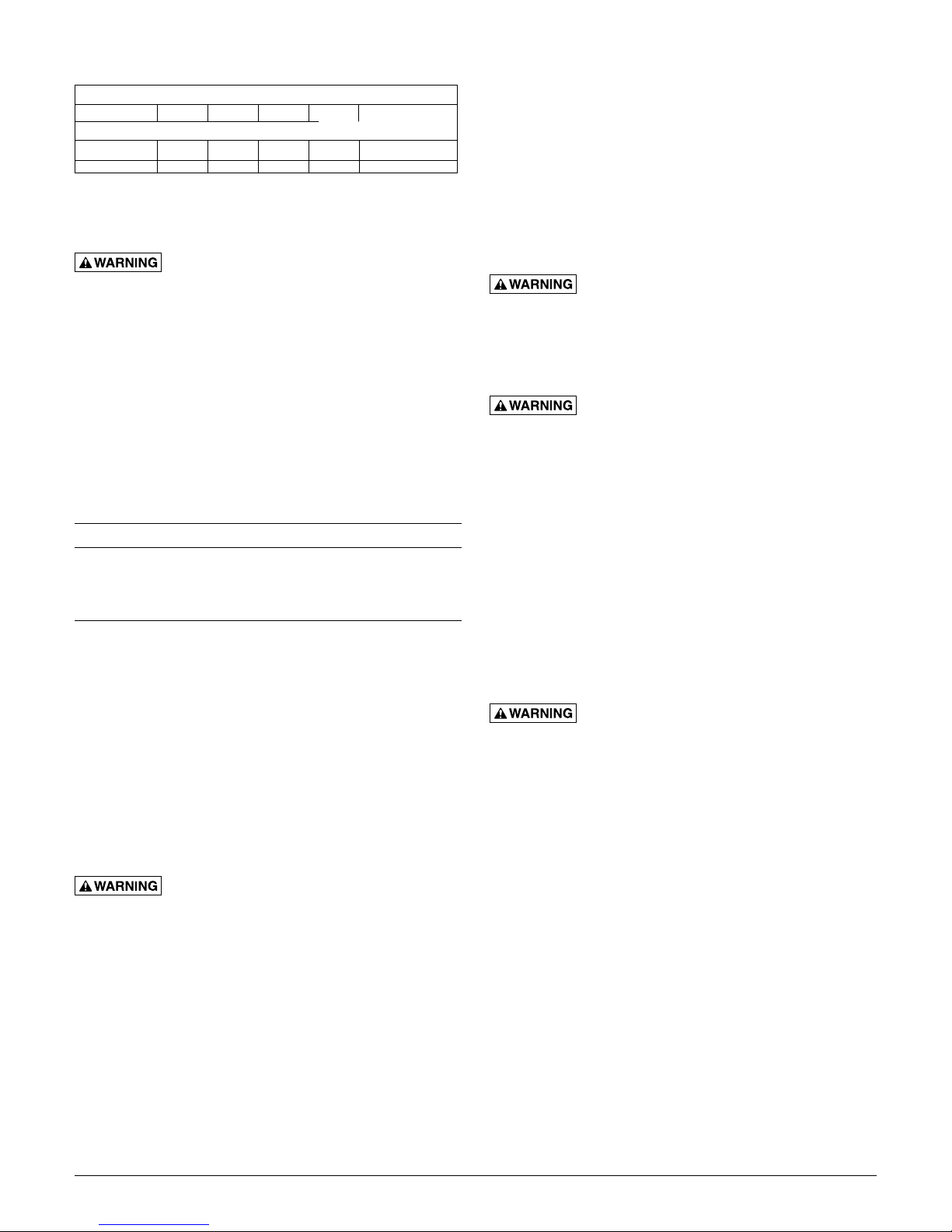
PERFORMANCE
GPM AT TOTAL FEET
Model 5 10 15 20
CAPACITY GALLONS/MINUTE
HTS33A1* – 42 30 10 21
HTS33M1* – 42 30 10 21
*For performance at maximum temperature see Catalog.
No flow
at height shown below
INSTALLATION
Hazardous voltage. Can shock, burn or kill.
Do not lift pump by the power cord. See “Cord Lift Warning”
on Page 3.
NOTICE: Install the pump on a hard, level surface (cement,
asphalt, etc.). Never place the pump directly on earth, clay or
gravel surfaces.
5. DO NOT remove the grounding prong from the plug
or modify the plug. To protect against electrical shock,
the power cord is a three-wire conductor and includes
a 3-prong grounded plug. Plug the pump into a 3-wire,
grounded, grounding-type receptacle. Connect the pump
according to the NEC or CEC and local codes.
For automatic operation, plug or wire the pump into the
automatic float switch. The pump will run continuously when
plugged directly into an electrical outlet.
Connect or wire pump to its own individual branch circuit
with no other outlets or equipment in the circuit. Size fuses
or circuit breakers according to the “Motor, Switch and Cord
Specifications” chart.
Risk of electrical shock and fire. Can
burn, kill or cause property damage. Be sure that power
supply information (Voltage/ Hertz/Phase) on pump motor
nameplate matches incoming power supply exactly. Install
pump according to all electrical codes that apply.
Piping
Piping must not be smaller than pump discharge.
When installed in an effluent system, the pipe must be
capable of handling semi-solids of at least 3/4" (19mm) in
diameter.
The rate of flow in the discharge pipe must keep any solids
present in suspension in the fluid. To meet minimum flow
requirements (2 feet per second in the discharge line), size
the pipe as follows:
A Pipe Size Of: Will Handle a Flow Rate Of:
1-1/2" (38mm) 12 GPM
2" (51mm) 21 GPM
2-1/2"(64mm) 30 GPM
3"(76mm) 48 GPM
In an effluent system use a 1-1/2" (38mm) check valve
in pump discharge to prevent backflow of liquid into sump
basin. The check valve should be a free flow valve that will
easily pass solids. Be sure check valve installation complies
with local codes.
NOTICE: For best performance of check valve when
handling solids, do not install it with the discharge more than
45° above the horizontal. Do not install the check valve in a
vertical position as solids may settle in the valve and prevent
it from opening on startup.
Drill a 3/16" (5mm) hole in the discharge pipe about 1–2"
(25-51mm) above the pump discharge connection (but below
check valve) to prevent airlocking the pump.
Electrical
Hazardous voltage. Can shock, burn, or
kill. When installing, operating, or servicing this pump, follow
the safety instructions listed below.
1. DO NOT splice the electrical power cord.
2. DO NOT allow the electrical cord plug to be submerged.
3. DO NOT use extension cords. They are a fire hazard and
can reduce voltage sufficiently to prevent pumping and/or
damage motor.
4. DO NOT handle or service the pump while it is connected
to the power supply.
OPERATION
personal injury, property damage or death. Do not use in
explosive atmospheres. Pump water only with this pump.
NOTICE: Do not allow the pump to run in a dry sump. It will
void the warranty and may damage the pump.
An automatic overload protector in the motor will protect
the motor from burning out due to overheating/overloading.
When the motor cools down, the overload protector will
automatically reset and start the motor.
If the overload trips frequently, check for the cause. It could
be a stuck impeller, wrong/low voltage, or an electrical failure
in the motor. If an electrical failure in the motor is suspected,
have it serviced by a competent repairman.
The pump is permanently lubricated. No oiling or greasing is
required.
Risk of fire or explosion. Can cause severe
SERVICE
General
Hazardous voltage and risk of cord
damage. Can shock, burn, or kill. Before removing the
pump from the basin for service, always disconnect electrical
power to the pump and the control switch. Do not lift the
pump by the power cord. See the “Cord Lift Warning” below.
After removing the basin cover and the necessary discharge
piping, lift the pump out of the basin.
Place the pump in an area where it can be cleaned
thoroughly. Remove all scale and deposits on the pump.
Submerge the complete pump in a disinfectant solution
(chlorox or chlorine bleach) for at least one hour before
disassembling the pump.
The pump motor housing contains a special lubricating oil
which should be kept clean and free of water at all times.
NOTICE: Whenever the motor housing is being removed for
service, remove oil and replace it with new oil at reassembly.
Use only oil listed in parts list in this manual. When filling
with new oil, DO NOT overfill. Allow about 7/8" (22mm) air
space from top of boss in housing for expansion of oil when
the pump is operating.
2

Green Wire
409 0893
Pump Disassembly
Oil Fill
Pump Disassembly
Impeller and Seal Replacement
A. Impeller removal (See the pump disassembly drawing at
right:
1. Remove the oil fill plug and turn the pump upside
down to drain oil.
2. Remove the capscrews holding the upper motor
housing to the lower motor housing; lift off the upper
motor housing and remove the motor lead wires from
the connector to detach upper housing from assembly.
The lead wires are fitted with quick connect terminals
for this purpose.
3. Remove the capscrews holding the lower motor
housing to the volute; lift off the lower motor housing.
4. Hold the rotor shaft assembly and unscrew the
impeller by turning it counter-clockwise. Remove
impeller and clean it.
If no more service is needed, reverse instructions above
to reassemble the pump. Reattach the motor lead wires
as shown in Figure 1, fill with clean dielectric oil (Part
No. U197-8A), check the oil level and replace fill plug.
Oil should cover the motor windings.
(connected between
the two tallest
dividers)
Either Black Wire
Short Divider
Either Black Wire
View A-A
Figure 1
B. Shaft seal replacement:
1. Follow the instructions to remove the impeller, above.
2. Remove the stator capscrews and the spacers (if
applicable). Lift off the stator.
3. Remove the seal’s ceramic seat from the shaft and tap
the body of the seal out of the lower motor housing.
4. Clean the seal cavity thoroughly before installing the
new seal. NOTICE: Make sure that the seal faces are
clean; do not scratch or damage the new seal face
during seal replacement. Apply Permatex #2 or an
equivalent sparingly to the outside edge of seal body
before installing the seal in the lower motor housing.
5. Press the new seal body into position in the lower
housing cavity.
6. Press the ceramic seat onto the motor shaft. The
impeller will pull it into position.
7. Reassemble the stator and tighten the stator
capscrews.
8. Reassemble the impeller and the pump (reverse
instructions 1 through 4 in section A).
9. Reattach the motor lead wires as shown in Figure 1.
10. Fill with clean dielectric oil (Part No. U197-8A), check
the oil level (it should be about 7/8" below the boss in
the motor housing to allow for expansion) and replace
the oil fill plug.
Pump Disassembly
HTS33 Series
Plug
Housing
Capscrew
Insulating
Disk
Rotor/Stator
Assembly
Stator
Capscrew
Grn
Blk
Blk
Power Cord
O-Ring
Lower
Motor
Housing
Shaft Seal,
Stationary
Head Ass'y
Shaft Seal,
Rotating
Mating Ring
Impeller
Volute
410 0893
CORD LIFT WARNING
WARNING
Risk of electrical shock.
Can burn or kill.
Do not lift pump by
power cord.
1. Attempting to lift or support pump by power cord
can damage cord and cord connections.
2. Cord may pull apart, exposing bare wires with
possibility of fire or electrical shock.
3. Lifting or supporting pump by power cord will
void warranty.
4. Use lifting ring or handle on top of pump for
all lifting/lowering of pump. Disconnect power
to pump before doing any work on pump or
attempting to remove pump from sump.
3
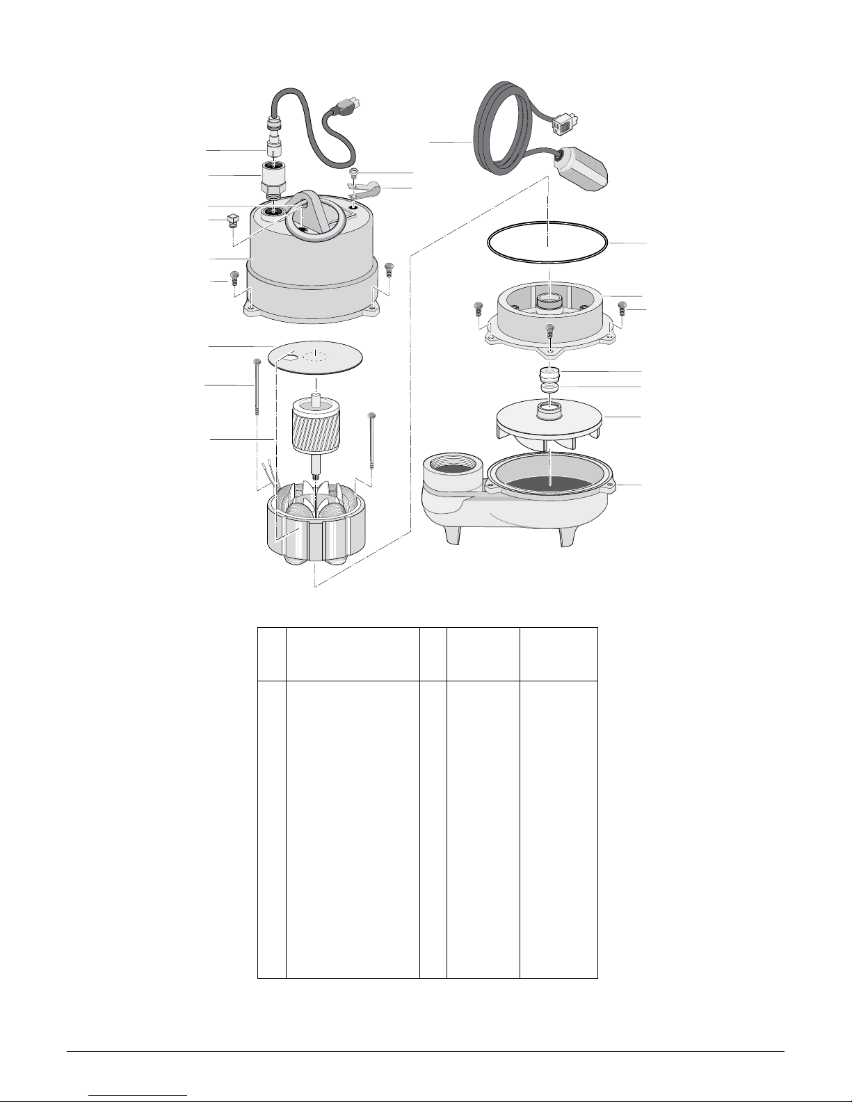
HTS33 SERIES EXPLODED VIEW
1
2
3
4
5
6
7
8
9
12
11
10
13
14
6
15A
15B
16
17
REPAIR PARTS LIST
Key Part HTS33A1 HTS33M1
No. Description Qty. 1/3 HP 115 V 1/3 HP 115 V
1 Power Cord 1 PW117-226-TSE PW117-106-TSE
2 Cord Connector 1 PS17-46P —
3 Handle Ring 1 U97-128 U97-128
4 1/4" NPT Plug 1 U78-57DT U78-57DT
5 Upper Motor Housing 1 PW18-22F PW18-22
6 #10-32 x 3/4" Capscrew 6 U30-482SS U30-482SS
7 Insulating Disk 1 PS18-82 PS18-82
8 #10-32 x 3-1/8" Capscrew 2 U30-949ZP U30-949ZP
9 Rotor/Stator Assembly 1 PS218-151 PS218-151
10 Switch Cord Clamp* 1 CC0030-13 —
11 #8-32 x 1/2” Capscrew* 1 U30-539SS —
12 Automatic Float Switch* 1 PW217-25 —
13 O-Ring 1 U9-339 U9-339
14 Lower Motor Housing 1 PW18-23AA PW18-23AA
15A Shaft Seal Stationary
Head Assembly 1 U9-379A U9-379A
15B Shaft Seal Rotating
Mating Ring 1 U9-321A U9-321A
16 Impeller 1 PW5-5 PW5-5
17 Volute 1 PW1-4 PW1-4
• Dielectric Oil 1 U197-8A U197-8A
• Not Illustrated.
4
 Loading...