

OWNER’S MANUAL
Utility Sink Pump
NOTICE D’UTILISATION
Pompe à usage général
pour évier
MANUAL DEL USUARIO
Bomba de uso general
para fregadero
Installation/Operation/Parts
For further operating, installation,
or maintenance assistance:
Call 1-888-957-8677
English .......................... Pages 2-6
293 WRIGHT STREET, DELAVAN, WI 53115 WWW.HYDROMATIC.COM
PH: 8889578677
© 2013 Pentair, Ltd. All Rights Reserved. HYD847 (Rev. 03/04/13)
HPUSP125
Installation/Fonctionnement/Pièces
Pour plus de renseignements
concernant l’utilisation,
l’installation ou l’entretien,
Composer le
Français ..................... Pages 7-11
1 (888) 957-8677
Instalación/Operación/Piezas
Para mayor información sobre el
funcionamiento, instalación o
mantenimiento de la bomba:
Llame al 1-888-957-8677
Español .................. Paginas 12-16
Safety 2
READ AND FOLLOW
SAFETY INSTRUCTIONS!
This is the safety alert symbol. When you see this
symbol on your pump or in this manual, look for one of
the following signal words and be alert to the potential for
personal injury:
warns about hazards that will cause serious
personal injury, death or major property damage if ignored.
personal injury, death or major property damage if ignored.
minor personal injury or property damage if ignored.
The label NOTICE indicates special instructions which are
important but not related to hazards.
Carefully read and follow all safety instructions in this
manual and on pump.
Keep safety labels in good condition.
Replace missing or damaged safety labels.
1. Read this manual carefully. Failure to follow these
instructions could cause serious bodily injury and/or
property damage.
2. Check your local codes before installing. You must
comply with their rules.
3. Connect the pump to a separate circuit with no other
appliances on the circuit. Consult a licensed electrician
for all wiring.
NOTICE: This pump does not require a connection to a
main stack vent, per the National Standard Plumbing Code
(NSPC) 2003 Section 11.7.9.
cause death. Unplug pump before working on it.
warns about hazards that can cause serious
warns about hazards that will or can cause
Hazardous voltage. Can shock, burn or
INSTALLATION
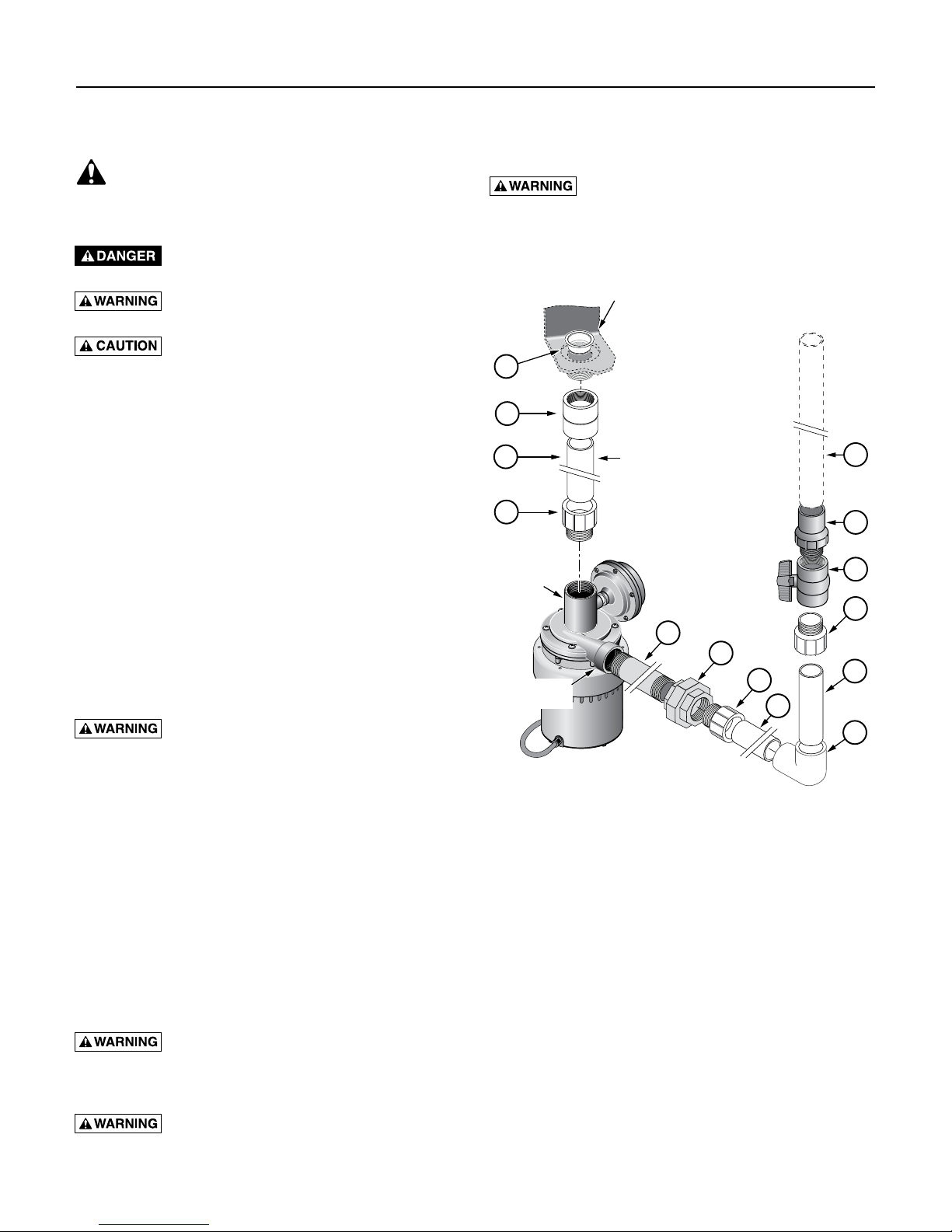
(SEE FIGURES 1 AND 2)
Electric Shock Hazard. Plug pump into a
properly grounded, GFCI protected outlet. Do NOT plug
in the pump until after it is completely installed. Do not
remove or modify the grounding pins on the plugs.
A
1
2
3
1-1/2” Pump
Inlet Port
1-1/4” Pump
Discharge
Sink Bottom with Drain Port;
Tail Piece integral with Sink
For easier maintenance,
use 2 short sections of
pipe connected by a
1-1/2” Solvent Union.
4
9
B
C
6
5
6
7
7
8
DESCRIPTION
This pump is designed to be used with a sink where a
gravity drain line is not available. Attach the pump to the
drain tail piece; the pump will start when water begins to
drain. Uses include basement laundry sinks, wet bars and
utility sinks.
SPECIFICATIONS
Power supply required ...................................115V, 60 HZ.
Liquid Temp. Range ..................... 32° – 120°F (0° – 50°C)
Individual Branch Circuit Required (min.) .............15 Amps
Pump Inlet ......................................................... 1-1/2" NPT
Pump Discharge ................................................ 1-1/4" NPT
Fire or explosion hazard. Do not use in
explosive atmospheres. Pump fresh water only with this
pump. Use with salt water or brine will void the warranty.
California Proposition 65 Warning
contain chemicals known to the State of California to
cause cancer, birth defects or other reproductive harm.
This product and related accessories
Fittings Supplied: Qty.
A Sink Drain Screen 1
B 1-1/4” NPT x 1-1/4” Slip Check Valve 1
C 1-1/4” NPT Ball Valve 1
Purchase Separately: Qty.
1 1-1/2” NPT x 1-1/2” Slip Female Adapter 1
2 1-1/2” Schedule 40 PVC Pipe, to fit 1
3 1-1/2” NPT x 1-1/2” Slip Male Adapter 1
4 1-1/4” NPT Galvanized Nipple (to fit) 1
5 1-1/4” NPT Galvanized Union 1
6 1-1/4” NPT x 1-1/4” Male Adapter 2
7 1-1/4” Schedule 40 PVC Pipe, to fit 4
8 1-1/4” Socket to Socket 90° Elbow 1
9 1-1/4” Schedule 40 PVC Pipe to Drain As Needed
PVC Pipe Cement As Needed
PTFE pipe thread sealant tape As Needed
1-1/2” Plastic Solvent Union
(For Drop Pipe – Optional)
NOTE: Be careful to avoid cross-threading;
Use only a plastic-compatible pipe-threading
compound or PTFE pipe thread sealant tape
when connecting threaded fittings to plastic adapters.
Figure 1: Typical method of mounting the pump.
Installation 3
PUMP INSTALLATION
Mount the pump
NOTICE: DO NOT use plumber’s pipe threading
compound (“pipe dope”) on plastic pipe; it can damage
the plastic, causing leaks and piping failure and voiding
the warranty.
1. Place the sink in its final location.
2. Remove any existing drain fittings back to the tail
piece (Figure 1). Make sure the existing tail piece does
not leak.
NOTICE: If the sink-drain tail piece is not 1-1/2" NPT,
you will have to adapt it (bushings, reducers, etc.). In
this case, wrap all joints with PTFE pipe thread sealant
tape before making connections.
3. Glue the 1-1/2” PVC pipe into the female adapter
(purchase separately).
follow the cement manufacturer’s instructions when
using PVC cement. Do not use near fire or open
flame.
4. Wrap the threads of the tail piece with 1 to 1-1/2
turns of PTFE pipe thread sealant tape. Thread the
1-1/2" NPT female adapter onto the sink-drain tail
piece. Thread it hand tight plus 1/2 turn with a pipe
wrench or slip joint pliers. DO NOT overtighten.
* Required and included
** Purchase separately
†
For easier removal for servicing or cleaning,
install a 1-1/2” solvent union in the drop pipe.
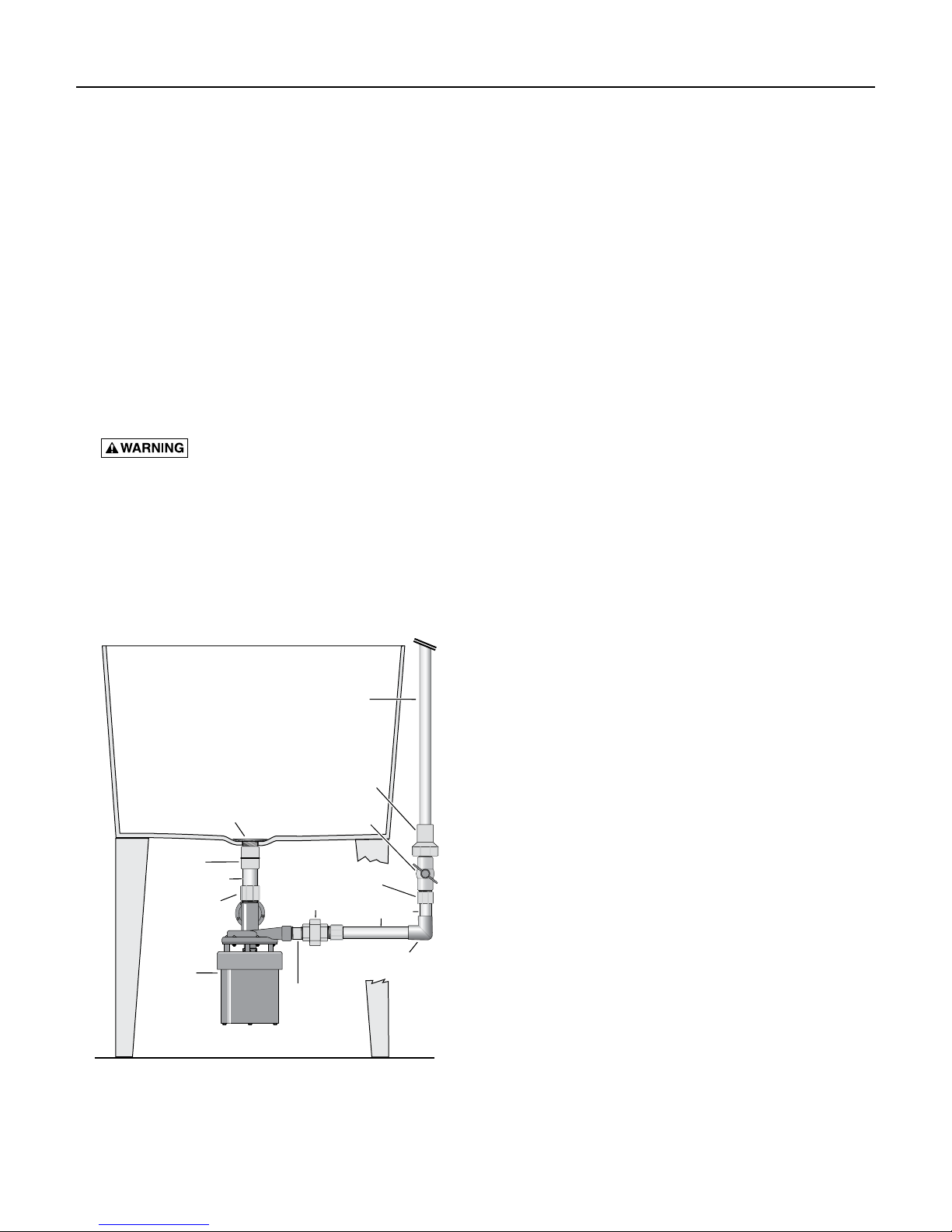
Figure 2: Pump Installed.
Fire and explosion hazard. Be sure to
Discharge Pipe**
Laundry
Sink
Check Valve*
Shut-Off/FlowBalancing Valve*
1-1/4” Male Adapter**
1-1/4” Union**
1-1/4” Socket to
Socket 90° Elbow**
1-1/4” Nipple**
1-1/2” Female
Adapter**
1-1/2” PVC**
1-1/2” Male
Adapter**
Pump*
Screen*
†
1-1/4” PVC
5799 0308
5. Wrap the threads of the 1-1/2” male adapter with
1 to 1-1/2 turns of PTFE pipe thread sealant tape
and install it in the pump inlet. Tighten it hand tight
plus 1/2 turn with a pipe wrench or slip joint pliers.
DO NOT overtighten!
6. Measure the 1-1/2” PVC pipe against the drain and
the pump and trim the pipe to fit.
7. Do a trial assembly (dry - no glue) of the pump onto
the drain pipe. Swing the pump until it accurately
faces the discharge piping, and then mark the pump
and the inlet pipe/adapter assembly so that you
can accurately install the pump in Step 8. Arrange
a temporary support under the pump to relieve the
strain on the sink drain piping while the glue is
setting. Leave it in place while you measure and cut
the discharge piping (Step 12).
8. Slide the pump up into position and glue the pipe into
the male adapter (on the pump).
• Don’t allow any glue to get on the pump or in
the motor;
• Make sure the pump is facing the correct direction
(match the marks from Step 7);
• Put the support in place under the motor.
9. Wrap the 1-1/4” galvanized nipple with 1-1/2 to 2
turns of PTFE pipe thread sealant tape on each end
and thread it into the pump discharge port.
NOTICE: Tighten this only enough to prevent leaking.
Over-tightening can crack the plastic.
10. Hold the nipple with a pipe wrench and thread one
half of the 1-1/4” union onto it, hand tight plus 1-1/2
turns with a pipe wrench or slip-joint pliers.
11. At this time, wrap the threads on both the 1-1/4”
male adapters with 1-1/2 to 2 turns of PTFE pipe
thread sealant tape. Thread one of the adapters into
the other half of the 1-1/4” union, hand tight plus
1/2 turn with a wrench or a pair of slip-joint pliers.
DO NOT overtighten!
12. Install the discharge piping as shown in Figures 1
and 2. The order is:
1-1/4” PVC Pipe cut to fit,
90° Socket to Socket elbow,
1-/14” PVC Pipe cut to fit,
Male adapter,
Flow Control/Ball Valve,
Check Valve,
(NOTICE: Install the check valve in the vertical
discharge pipe with the threads down. Be sure the flow
arrow points AWAY from the pump. That is, when the
check valve is correctly installed, the arrow showing
direction of flow should point UP.)
1-1/4” Outlet Pipe.
13. Connect the discharge piping to the building drain.
Plug in the Pump
AFTER the pump is completely installed, plug the switch
into a GFCI-protected, properly grounded outlet. Plug the
pump into the back of the switch’s plug.
Installation / Maintenance 4
Adjusting The Flow
The drain pump can pump up to 27 gallons per minute
(GPM). Normal sink drains allow only 5 to 6 GPM to
flow. Adjust the discharge shut-off/flow balancing valve as
follows so that the pump does not cycle on and off when
the faucets are on full.
1. Run water into the sink. The pump will start when it
detects water.
2. Check for leaks. If leaks are found, unplug the pump
power cord and fix the leaks before proceeding.
3. Put a stopper in the drain and allow the sink to fill up
a few inches.
4. Open the discharge shut-off valve, open the faucets,
and remove the stopper to drain the sink.
5. The pump will start. Adjust the discharge shut-off/flow
balancing valve until the pump runs continuously
while the faucets are running and the sink is draining.
If the water level rises with the pump on, slightly open
the discharge valve to balance the flow. If it drops,
slightly close the discharge valve.
Washing Machine Use
Washing machines usually discharge more water than
the faucets do, and it is normal for the water level to rise
in the sink while the pump is discharging. Do not adjust
the discharge valve to match the flow w hen the washing
machine discharges into it, unless the sink is ONLY used
for washing machine discharge.
NOTICE: Washing machine discharge water contains
fiber and lint. Unfiltered washing machine discharge
could plug the pump and require pump disassembly for
cleaning. To avoid this, install a lint trap or bag type filter
in the washing machine discharge line and clean it out
regularly.
MAINTENANCE
This pump requires very little maintenance and should
provide a long service life. Problems are rare; when the
pump flow drops off, the most likely cause is something
solid going down the drain and jamming the impeller.
To clear a jammed impeller:
1. Unplug the Pump.
2. Close the discharge shutoff valve.
3. Bail out the sink as much as possible.
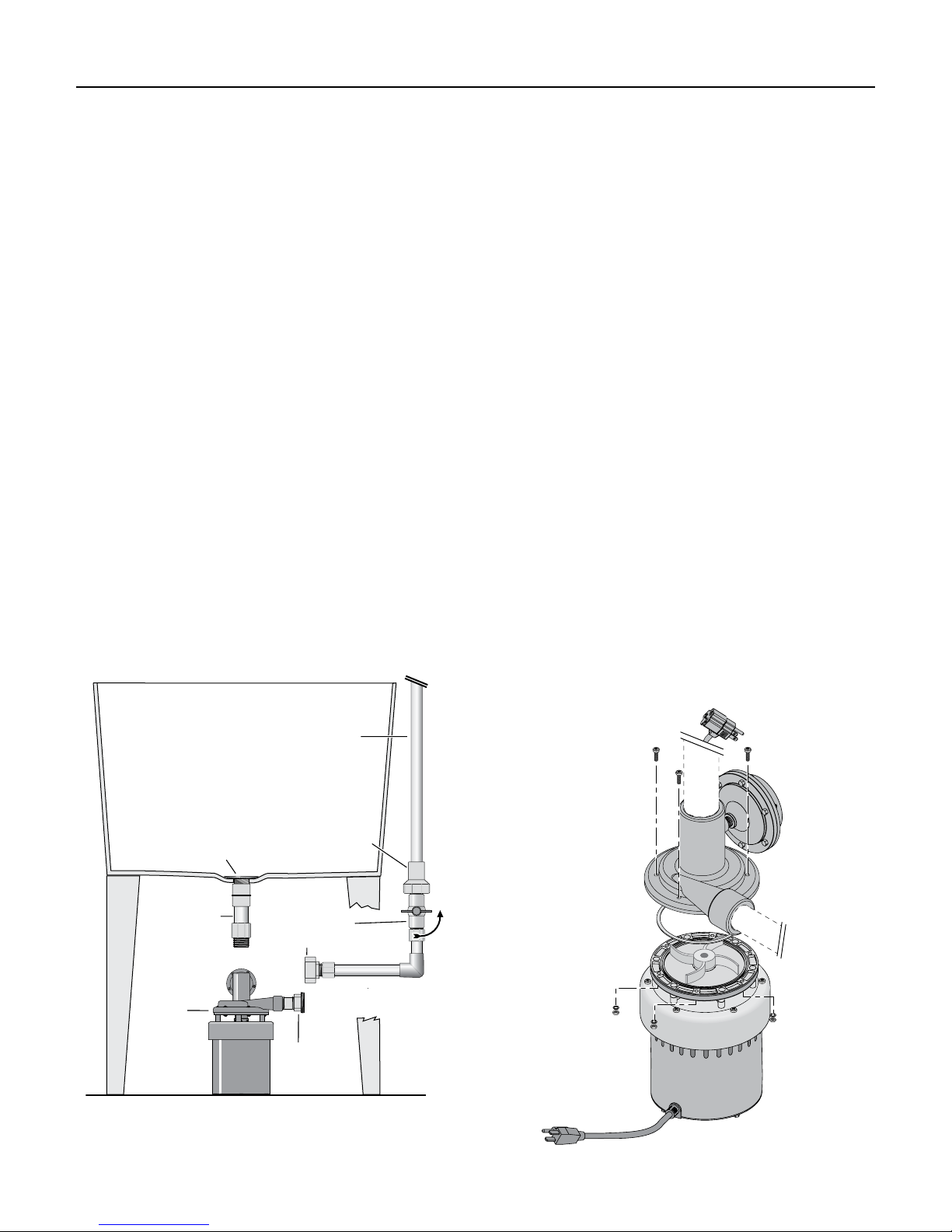
4. Disconnect the union, unscrew the pump from the
sink tail piece, lower the pump to the floor, and slide
it out from under the sink (see Figure 3).
5. Remove the six housing screws (see Figure 4).
6. Clean out the pump. Make sure that the pump
discharge is clear. If necessary, replace the impeller.
7. Install the new gasket (included with impeller).
Reassemble the pump.
8. Raise the pump back into position, thread it back onto
the sink tail piece, and reconnect the union.
9. Plug in the pump. Run water in the sink until the
pump has run at least one complete cycle to make
sure the pump is operating correctly and there are
no leaks.
Discharge Pipe
Discharge Pipe
Laundry
Laundry
Sink
Sink
Check Valve
Screen
Screen
†
1-1/2” PVC
1-1/2” PVC
Pump
Pump
†
†
For easier removal for servicing or cleaning,
For easier removal for servicing or cleaning,
install a 1-1/2” solvent union in the drop pipe.
install a 1-1/2” solvent union in the drop pipe.
†
Check Valve
Shut-Off/Flow-
Shut-Off/FlowBalancing Valve
Balancing Valve
1-1/4” Union Half
1-1/4” Union Half
1-1/4” Union
1-1/4” Union
Half
Half
Figure 3: Pump Removal.
5800 0308
5800 0308
5801 0308
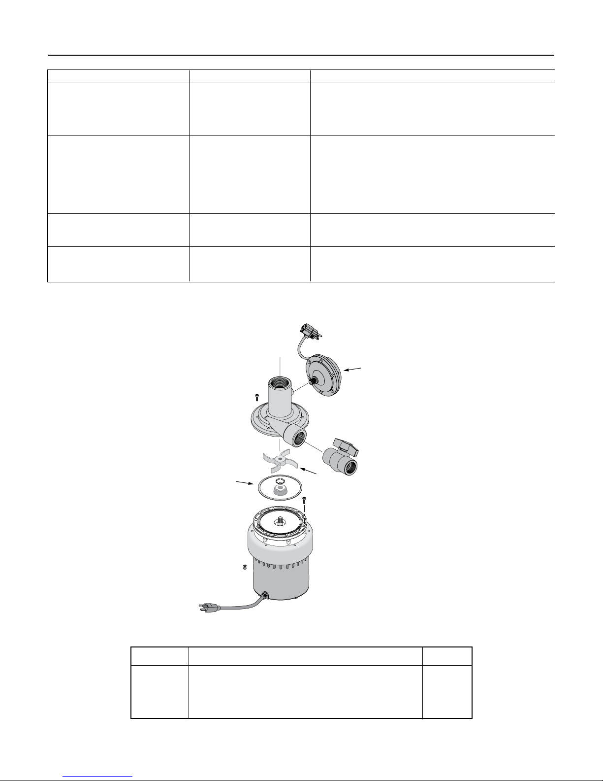
Figure 4: Remove 6 housing screws to clean out pump.
Troubleshooting 5
SYMPTOM POSSIBLE CAUSE(S) CORRECTIVE ACTION
Pump does not run when water Pump unplugged. Plug in pump.
flows in from sink
Pump impeller jammed. Unplug pump; follow procedure under “Maintenance”
to clear pump.
Sink stopper in drain. Remove stopper.
Pump runs, but does not empty Drain clogged. Clear drain screen.
sink
Clogged discharge line. Unplug pump, open and clear discharge line.
Shut-off valve closed. Open shut-off valve slightly.
System discharge line too Unplug pump and reduce height or length of discharge line
high or too long. (11’ Max. Height).
Check valve installed Make sure flow arrow on check valve points away
backwards from pump.
Pump cycles on and off when Check valve not installed. Unplug pump and install check valve (see Figures 2
no water is in the sink and 3, Pages 3 and 4).
Check valve jammed. Unplug pump; open discharge line and clean check valve.
Pump cycles on and off when the Shut-off valve not adjusted. See “Adjusting the Flow”, Page 3.
sink is at maximum water
flow or is full
Outlet unpowered. Check fuse / breaker.
Shut-off valve not installed. Unplug pump and install shut-off valve (see Figures 2
and 3, Pages 3 and 4).
1
3
2
5802 0308
REPAIR KIT, Part No. PS20-137REP
Key No. Part Description Qty.
Kit Includes:
1 Diaphragm Switch 1
2 Impeller 1
3 Gasket 1
 Loading...