

Pentair Hydromatic S4PP, Hydromatic H4HP, Hydromatic H3HP, Hydromatic S4MP, Hydromatic S4HVP Installation And Service Manual
...
INSTALLATION AND SERVICE MANUAL
HYDROMAT IC
SUBMERSIBLE
SOLIDS HANDLING
PUMP
Models
C4S(X)P, H3H(X)P,
H4H(X)P, S4M(X)P,
S4P(X)P, S4HV(X)P
and S4MV(X)P
(Class I, Division 1, Groups C & D): FM
ENGLISH: PAGES 2-12
Installation and Service Manual
For use with product built with Premium
Efficient motor.
Make sure this manual is provided to the owner
of the equip ment or to the responsible party who
maintains the system.
NOTE! To the installer: Please make sure you provide this manual to the owner of the equip ment or to the responsible
party who maintains the system.
Item # E-03-557 | Part # 056255571 | © 2018 Pentair plc | 09/25/18
(Hazardous Location
Motor End)

General Information
Attention:
This manual contains important
information for the safe use of this
product. Read completely and do not
throw away.
Reasonable care and safe methods
should be practiced. Check local codes
and requirements before installation.
Unpacking Pump:
When unpacking unit, check for damage.
Claims for damage must be made at
the receiving end through the delivery
carrier. Damage cannot be processed
from the factory.
WARNING: Before handling these
pumps and controls, always
disconnect the power first. Do not
smoke or use sparkable electrical
devices or flames in a septic
(gaseous) or possible septic sump.
CALIFORNIA PROPOSITION 65 WARNING:
This product and
related accessories contain
chemicals known to the State of
California to cause cancer, birth
defects or other reproductiveharm.
Pumps in Storage or Not Operating:
Pumps with silicon/carbide seals
must have impellers manually rotated
(6 revolutions) after setting nonoperational for 3 months or longer and
prior to electrical start-up.
Pumps with tungsten carbide seals
must have impellers manually rotated
(6 revolutions) after setting nonoperational for 3 weeks or longer and
prior to electrical start-up.
Seal Failure Probes:
All hazardous location submersible
pumps have two factory installed
moisture detectors (seal failure
probes). They are in a normally open
series circuit in the seal chamber.
Under normal operating conditions,
the circuit remains open. If the lower
seal leaks and moisture enters this
chamber, the moisture would settle to
the bottom of the chamber and will
complete the circuit between the
moisture detectors.
This circuit must be connected to a
sensing unit and signaling device. This
is supplied in a Hydromatic® built control
panel.
NOTE: Failure to install such a device
negates all warranties by Hydromatic.
Heat Sensors:
All motors in this family have heat
sensors on or embedded in the motor
winding to detect excessive heat.
This prevents damage to the motor.
If sensor trips due to excessive
winding temperature, the starter in
the panel breaks power to the pump.
Once the sensor resets, the starter is
automatically reset for FM for continued
operation of the pump. This circuitry is
supplied in a Hydromatic control panel.
The sensors are set to trip at 130°C.
NOTE: Failure to install such circuitry
would negate FM approvals and all
warranties by Hydromatic.
Power Cords:
The power cord and heat sensor seal
failure cord are potted into the cord
cap. The cords must not be spliced.
NOTE: Each cable has a green lead.
This is the ground wire and must
be grounded properly per NEC and/
or local codes. Cords should be
inspected for abnormal wear and
replaced accordingly.
Overload Heaters:
If the Hydromatic electrical panel is not
used, starters with 3 leg overload relay
must be supplied on 3 phase pumps.
Each leg is to have an identical heater
sized in accordance with the nameplate
amps on the motor housing. The amp
draw on these submersible motors is
slightly higher than a corresponding
horsepower surface motor, so heaters
must be sized by the nameplate rating.
Capacitor start single phase pumps
have a run and start winding that draws
different currents. To adequately
protect these windings with the
appropriate heaters, consult the
factory.
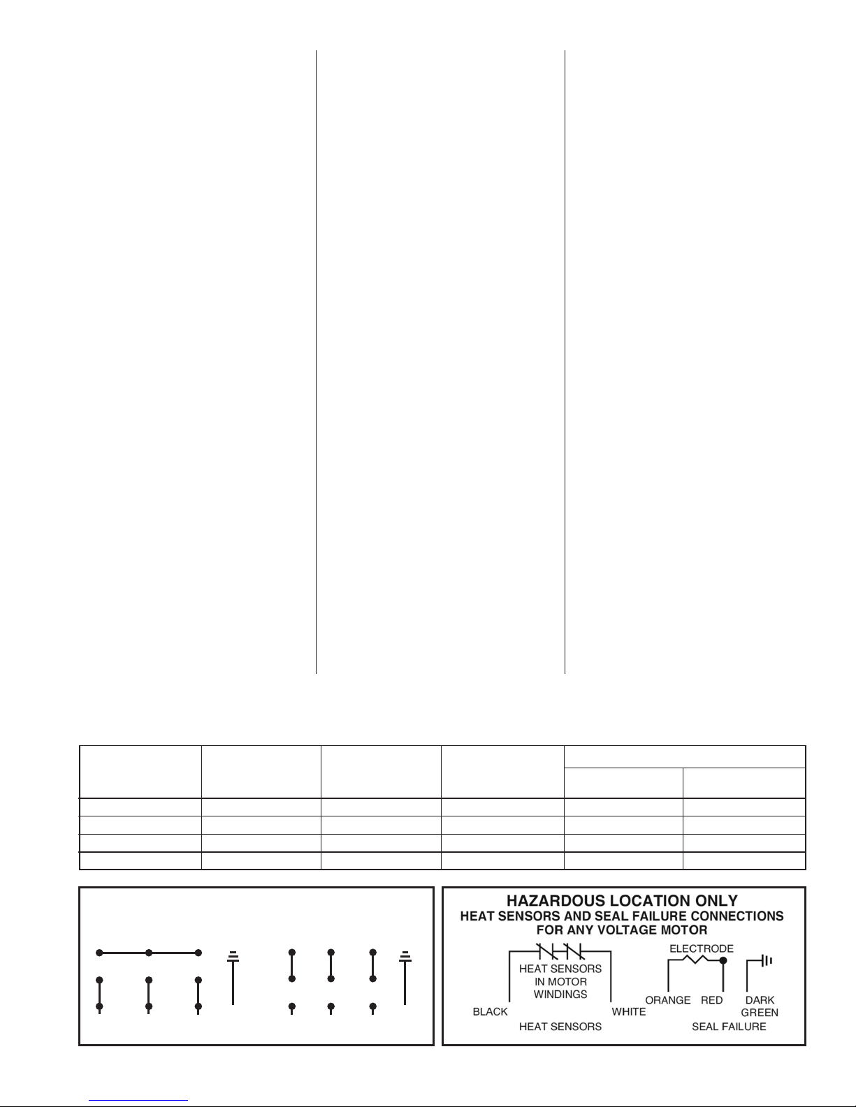
NOTE: The red lead is always the
start winding of a pump using single
phase.
Pump Installation
Installing Sump Level Controls Float
Controls:
In either simplex, duplex or triplex
systems the lower or turn-off control
is to be set to maintain a minimum level
in the sump. This level shall be no more
than 3-1/4" from the top of the motor
housing down to the surface of the
sewage.
The second or turn-on control is set
above the lower turn-off control. The
exact distance between the two floats
must be a compromise between a
frequent pumping cycle (10 starts per
hour max.) to control septicity, solids
and a slower cycle for energy economy.
This distance should be determined by
the engineer or consulting engineer,
depending on the conditions of
the application.
Installing Pump in Sump:
Before installing the pump in the
sump, lay it on its side and rotate
impeller. Impeller may be slightly
stuck due to factory test water.
The impeller should turn freely.
Do not connect the power until
after this test.
Clean all debris from sump and connect
pump to piping. A check valve must
be installed on each pump. A gate or
plug valve in each pump discharge is
highly recommended. This valve should
be installed on the discharge side of the
check valve so if necessary to service
the check valve, the line pressure can
be cut off. Single pump systems are
sometimes installed without a check
valve where it is desirable to self-drain
the discharge line to prevent freezing.
This can be done only with short
discharge lines; otherwise water will
return to the sump and cause short
cycling of the pump.
Making Electrical Connections:
All electrical wiring must be in
accordance with local codes, and only
competent electricians should make
the installations. Complete wiring
diagrams are glued to the inside
cover of the panel. All wires should be
checked for grounds with an ohmmeter
or Megger® after the connections are
made.
2
THIS IS IMPOR TANT, AS ONE GROUNDED
WIRE SIZE TABLE
FOR REMOTE LOCAT ION OF CONTROL PA NEL
LENGTHS ARE BASED ON A VOLTAGE DROP OF TWO PERCENT
Maximum length in feet from NEMA 4 Junction Box to control panel. All contro l wire s can be = 14–16 or 18 gauge wire. If power lines are greater than
300 volts, and the control wires are used in the same conduit, then the insulation of the control wires must be for 600 volts.
1 Phase 3 Phase
HP HP
Wire Size Volts 1
1
⁄2 2 3 5 Volts 11⁄2 2 3 5 71⁄2 10 15
200V - - - - 200 217 190 101 - - - -
230 105 95 - - 230 291 250 134 - - - -
12 460 1165 1019 540 412 333 233 -
575 1820 1450 820 624 515 364 -
200 121 111 103 - 200 340 297 158 119 - - -
230 163 148 139 - 230 456 390 210 161 - - -
10
460 1822 1594 846 645 522 364 -
575 2847 2270 1360 976 806 569 -
200 190 175 162 - 200 533 466 249 187 155 - -
230 257 232 219 - 230 715 613 330 252 204 - -
8 460 2860 2500 1328 1013 819 572 390
575 4468 3570 2145 1532 1266 894 -
200 296 272 252 - 200 830 726 387 291 242 170 -
230 400 362 340 181 230 1114 955 514 393
318 223 -
6 460 4455 3898 2068 1577 1275 891 607
575 - - 3341 2386 1972 1392 -
200 452 416 384 - 200 1268 1110 592 444 370 260 -
230 610 553 520 276 230 1701 1458 785 601 486 340 232
4 460 - - 3160 2410 1449 1361 928
575 - - - 3646 2513 2127 -
200 689 633 586 - 200 1932 1690 902 676 563 395 -
230 930 842 792 421 230 2592 2222 1196 915 741 578 353
*2* 460 - - - 3672 2969 2074 1414
575 - - - - 4590 3240 -
*Special junction box required for wire sizes larger than #4.
WIRE CAN CAUSE CONSIDERABLE
TROUBLE.
IMPORTANT: If equipment is not
properly wired and protected as
recommended, the warranty is void.
Caution: The 230 volt 3 phase pump
has a dual marked nameplate. Voltage
may be rewired by the manufacturer
or a Class I Div 1 equipment qualified
electrician. Once the voltage is changed,
the factory cord tag indicating 230 volt
3 phase must be removed.
For record keeping purposes, we
suggest the pump be marked externally
with the new voltage and qualified
personnel that performed the change.
Pumps shipped from the factory as 460
volt 3 phase cannot be rewired to any
other voltage.
To Re-wire the pump from 230V to
460V 3 phase:
Only a 230V pump from the factory
is considered dual voltage, a cord
label clearly states the factory wound
voltage.
Remove all six cap screws then raise
the cord cap assembly enough to slip
a prying instrument on opposite sides
between the cord cap casting and
the motor housing. Take care to not
damage the o-ring or the machined
surfaces of the castings. Doing so
could void FM agency certifications.
While prying evenly on both sides;
NUMBER OF CONDUCTORS REQUIRED BETWEEN CONTROL PANEL AND NEMA 4 JUNCTION BOX
POWER LINES AND CONTROL WIRES CAN BE CARRIED IN CONDUIT OR CAN BE UNDERGROUND BURIED CABLE
System Number of Number of Number of
Type Control Wires Power Lines Ground Wires #8 Number of Number of
Sensor Wires Ground Wires
Simplex 4 3 1 3 1
Simplex with Alarm 6 3 1 3 1
Duplex 6 6 2 6 2
Duplex with Alarm 8 6 2 6 2
230V 3ø 460V 3ø
3 PHASE MOTOR WIRING
DUAL VOLTAGE
separate the cord cap casting from the
motor housing, the assembly is airtight
and will have a vacuum effect when
disassembling. Once separated, the
cord cap can be inverted and rotated
to the outside of the pump assembly,
and a bolt can be re-used to secure
the upside down cord cap to the motor
housing for ease of rewiring.
Refer to the wiring diagram within
this manual for wiring details. Once
all electrical connections are finished
and secure (a crimped electrical
connector is best to prevent issues
due to vibration if required), the cord
cap should be re-attached reversing
the steps above. Ensure the o-ring is
in place and perform a hi-pot test for
safety once everything is complete.
Heat Sensors and Seal Failure Connections:
Be sure heat sensor wires are
connected in series with the starter
coil. Connections are provided on the
terminal strip.
Pump Operations
Starting System:
1. Double check all wire connections.
2. Turn pumps to Off position on
H-O-A switches.
3. Turn on breakers.
4. When using single phase pumps,
make sure red pump lead is
connected to capacitor circuit.
Connect amprobe to pump power
cord and turn pump on. The pump will
show high amp draw momentarily,
then as pump comes off start wirings,
amps will drop to normal nameplate
amps.
When using three phase pumps
(230/460/575), turn the H-O-A
switch to Hand position on one
pump and notice operation. If
pump is noisy and vibrates, rotation
is wrong. To change rotation,
interchange any two line leads to
pump. Do not interchange main
incoming lines. Check rotation of
all pumps in this same manner.
5. Now set both H-O-A switches to
Auto position and allow water to
rise in sump until one pump starts.
Allow pump to operate until the
level drops to turn-off point.
6. Allow sump level to rise to start
other pump(s). Notice run lights
in panel. Pumps should alternate
on each successive cycle of
operation.
7. Turn both H-O-A switches to Off
position and allow sump to ll to
the override control level(s).
8. Turn switches to Auto position, and
pumps should start and operate
together until level drops to turnoff point.
9. Repeat this operation and cycle
several times before leaving the
job.
HEAT SENSOR & SEAL FAILURE
45 6
78 9
12 3
BL
(L1)
W
(L2)
GREEN GREEN
R
(L3)
45 6
78 9
12 3
BL
(L1)
W
(L2)
R
(L3)
ELECTRODE RESISTANCE 330 kΩ
3
10. Check voltage when pumps are
operating and check the amp draw
of each pump. Check amps on each
wire as sometimes a high leg will
exist. For excessive voltage on one
leg, the electric utility company
should be consulted.
Pump Maintenance
As the motors are oil filled, no lubrication
or other maintenance is required.
If the heat sensor and seal failure are
hooked up properly, no attention is
necessary as long as the seal failure
indicator light does not come on. To
ensure continuity of the seal sensor
leads, a test light is provided on
intrinsically safe Hydromatic panels as
standard equipment.
Pump should be checked every quarter
for corrosion and wear.
Field Service on Hydromatic Hazardous Location Pumps:
If a Hydromatic hazardous location
pump is used in a hazardous location,
the pump must be returned to the
factory for electrical and motor
service. This will ensure the integrity
of the hazardous location rating of the
pump and comply with our warranty
requirements.
A
The quick disconnect cords, upper
and lower seal, volute and impeller
components may be repaired or
replaced by an authorized Hydromatic
service facility without compromising
the hazardous location rating to the
pump.
Any time the seal is disturbed, it must
be replaced.
Check the pump for proper rotation
before returning to service.
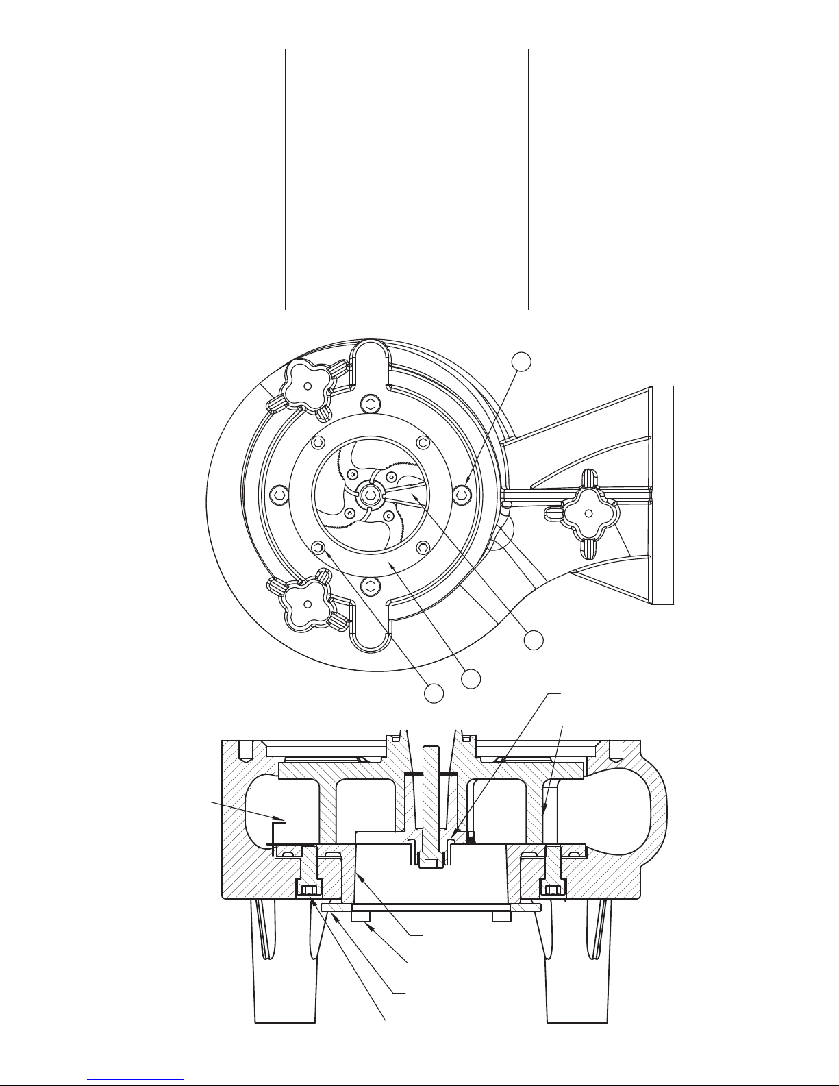
RECOMMENDED
MAX CUTTER GAP
.015
.010
B
C
CHOPPER PLATE
3/8-16 BOLTS
PLATE RETAINING RING
1/2-20 BOLTS
D
CUTTER INSERT
IMPELLER
4
 Loading...