

Page 1
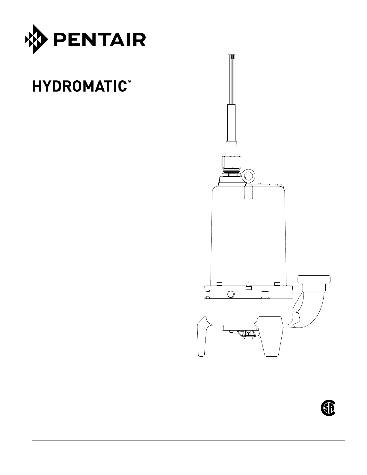
HV200 SERIES
GRINDER PUMPS
INSTALLATION AND SERVICE MANUAL
NOTE! To the installer: Please make sure you provide this manual to the owner of the equip ment or to the responsible
party who maintains the system.
Part #HYD1045 | © 2017 Pentair plc | 05/09/17
Page 2

SAFETY WARNINGS:
This manual contains important information for the safe use
of this product. Read this manual completely and follow
the instructions. Check local codes and requirements
before installation.
DANGER: Risk of Electrical Shock or Electrocution. May result
in serious injury, death or re hazard. Installer must disconnect
all electrical sources prior to installation, handling or servicing.
Only qualied personnel may install this system. NFPA 70/
National Electric Code (NEC) or local codes must be followed.
System must be properly grounded according to NEC.
DANGER: Biohazard Risk. Once wastewater source has
been connected to system, biohazard risk exists. Service
personnel must use proper personal protective equipment
and follow handling procedures per OSHA 29 CFR 1910.1030
when handling equipment after wastewater source has been
connected to system.
DANGER: Risk of Asphyxiation. Service personnel must use
proper personal protective equipment and follow OSHA 29 CFR
1910.146 or OSHA 29 CFR 1926. Pump may be installed in a
location classied as a conned space.
DANGER: Risk of Fire or Explosion. Do not smoke or use open
ames in or around this system. This system is not intended for
use in hazardous locations per NFPA 70 National Electric Code.
Do not pump ammable liquids.
DANGER: Cutting Risk. Risk of serious cutting or amputation
exists. Disconnect all power sources prior to servicing pump.
Pump may start without warning. Use caution when handling
grinder mechanism as it is extremely
Do not modify the cord strain relief. When wiring to a system
control, connect the pump ground lead to the system ground.
Do not run the pump dry. Dry running can overheat the pump
causing burns to anyone handling it and will void the warranty.
CALIFORNIA PROPOSITION 65 WARNING:
This product and related accessories contain
chemicals known to the State of California to cause cancer, birth
defects or other reproductive harm.
Submersible grinder pumps are not approved for use in
swimming pools, recreational water installations, decorative
fountains or any installation where human contact with the
pumped uid is common. This specialized pump is designed
to incorporate a grinding mechanism to remove wastewater
particulate and pump the resulting slurry.
On single and three-phase pumps, the motor protection must
be provided by the installer. All three-phase pumps must be
installed with magnetic starters having three-leg overload
protection in accordance with the national electric code. For
duplex installations, both pump motors must have separate
overload protection. Seal leak detectors must be connected to
the proper control circuitry.
Examine all lifting devices, rope or chain, for damage before
and after each lift. Do not use any lifting devices that are
not rated for and designed to lift the weights involved with
these
pumps.
Keep clear of suction and discharge openings and do not insert
ngers in the pump with the power connected. Make sure
lifting devices are securely fastened each time before lifting
pump and do not lift pump by the power cord. Do not exceed
manufacturer’s recommendation for maximum performance, as
this could cause the motor to overheat. Do not pump without
safety devices in
place.
sharp.
Control Panels and Controls: All Hydromatic
®
control panels used
on these grinders are UL listed and CSA certied. Intrinsically
safe type oat controls are recommended for all applications.
An intrinsically safe control panel relay will limit the current and
voltage to the level controls. Hydromatic control panels can be
supplied with this type circuitry.
The oat level controls maintain the basin sewage water level
by controlling pump turn-on and turn-o level. The lower
turn-o control should be set so that the pump stops at
approximately the top of the pump. The upper turn-on control
should be set above the lower turn-o control. The exact height
between the two controls is determined by the number of pump
starts desired and the depth of the basin. A maximum of 10
starts per hour should not be exceeded. The override control is
set at a specied height above the upper turn-on control. The
alarm control is set about 6" to 12" above the override control.
No control should be set above the inlet invert.
Pump: The HV200 pumps are equipped with 200 and 230
volt single-phase and 200, 230, 460 and 575 volt three-phase
with seal leak detector. HV200 Series pumps are available in
standard or high head ows. This pump is intended to grind and
pump all normal sewage.
Caution: Pump is only to be disassembled at Hydromatic
factory or an authorized Hydromatic service facility.
Single-phase motors are capacitor start, capacitor run and
the relays are mounted in the electrical control box. All singlephase motors must have a special electrical control box
by
Hydromatic. Installing single-phase motors with controls
other than Hydromatic voids warranty.
Pump has two oil-lled chambers, the motor and ball bearings,
and the seal chamber. The lower seal above the pump impeller
acts as a buer for the upper seal that holds oil in the motor
chamber. The lower seal detection will alarm if water enters the
chamber.
seal
Cords: Pump models with a seal leak detector use a ve-
conductor cord. The three power conductors are black, white
and red. The orange conductor connects to the seal leak probe
and the green conductor connects to the ground screw inside
the cord cap.
Single-phase pumps use the black and white as main winding
leads and the red for the start winding.
Cutters: The HV200 grinder is equipped with an axial style
cutter, a stationary plate and rotating cutter. To ensure proper
operation of the cutting mechanism, the gap between the
stationary plate and rotating cutter must be no more than .008".
If the pump is ever disassembled, the gap must be checked
before the pump can return to service. To check the gap, use
a .008" feeler gauge. If the .008" feeler gauge does not t
between the surface of the stationary cutter and rotating cutter
and the motor shaft turns freely, the gap is set properly. If the
.008" feeler gauge ts between the surfaces, shims must be
removed to close the
gap.
Three-Phase Control Box: Hydromatic three-phase control
equipment can be used for simplex or duplex operation. The
overload heaters are in accordance with full load amp
ratings.
If any amp readings are higher than listed, it indicates voltage
may be higher or lower than normal, or that the pump may
clogged.
be
Resistance of Winding: Every motor winding has a xed
resistance and windings must check close to the specication
values. This winding resistance also indicates if the motor is
connected for the voltage being used. Use ohmmeter to test
and read output directly in ohms.
2
Page 3

TROUBLESHOOTING
CONDITION PROBABLE CAUSE
Pump runs but does not pump liquid from basin.
Red light comes on at control box.
Overload trips and high water level alarms.
Yellow run light stays on continuously.
Circuit breaker trips.
Pump is noisy and pump rate is low.
Grease and solids have accumulated around pump
and will not pump out of the basin
Pump impeller may be air locked; this occasionally occurs in a new
installation. Start and stop pump several times to purge air.
Run additional water into basin so that the pump will be submerged
deeper to clear air.
If air does not clear, it may be necessary to lift pump out of sealing
elbow and start motor to allow pump to pump for a few seconds. If
discharge is piped in with union, slightly break union and start pump
to clear air.
If pump has been installed for some time and does not pump, it may
be clogged at grinder inlet.
Discharge gate valve may be closed.
Discharge check valve may be clogged or have a broken clapper.
Discharge head may be too high. Check elevation.
This indicates some water has leaked past the lower seal and has
entered the seal chamber and made contact with the electrode
probe. Pump must be removed from basin immediately for
replacement of lower seal.
Push in red reset button to reset overload. If overload trips again after
short run, remove pump and check for damage.
Check grinder for clogged material as this can cause an overload
condition on the motor
A faulty component in the control box could exist.
Indicates H-O-A switch may be in the Hand position.
Level control switch may have failed causing pump to continue to
operate when water is below lower
Grinder assembly may be partially clogged causing pump to operate
at very reduced capacity.
Check valve may be clogged causing low pump ow. Gate valve may
be in O position.
Pump may be air locked.
Reset breaker by pushing clear down on the handle, then put back
to the On position. If breaker trips again in a few seconds, that
indicates excessive load probably caused by a short in the motor or
control box.
If condition happens after an electrical storm, motor or control box
may be damaged by lightning.
A resistance reading of the motor with the lead wires disconnected
from the control box can determine if the trouble is in the motor or
control box.
Grinder assembly may be partially clogged with foreign objects
causing overload on the motor.
Grinder impeller may be rubbing due to bent shaft or misalignment.
Pump On switch may be set too high.
Run pump on Hand operation for several minutes with small amount
of water running into basin to clean out solids and grease. This allows
pump to break suction and break up the solids.
Trash may have accumulated around lower weight causing
pump to turn o too soon. Clean the trash from the weight and
suspension
cable.
oat.
3
Page 4

COMMON PARTS LIST
Item Engineering No. Description Qty.
1 28139B000 HVH200M2-2 Motor Assembly 1
28139B001 HVH200M6-2 Motor Assembly 1
28139B002 HVH200M3-2 Motor Assembly 1
28139B002 HVH200M4-2 Motor Assembly 1
28139B004 HVH200M5-2 Motor Assembly 1
28139B000 HVS200M2-2 Motor Assembly 1
28139B001 HVS200M6-2 Motor Assembly 1
28139B002 HVS200M3-2 Motor Assembly 1
28139B002 HVS200M4-2 Motor Assembly 1
28139B003 HVS200M7-2 Motor Assembly 1
28139B004 HVS200M5-2 Motor Assembly 1
28228B000 Impeller, HVH200, 6.25” O.D. 1
2
28228B001 Impeller, HVS200, 5.313” O.D. 1
144240025 Cord Cap, Standard, 20’ 12-7 1
3
144240115 Cord Cap, Standard, 35’ 12-7 1
4 28145B000 Rotating Cutter 1
5 28227B000 Stationary Cutter 1
6 21576A010 Seal, 7/8” Shaft, Upper 1
7 21576A010 Seal, 7/8” Shaft, Lower 1
8 28132B000 Motor Dome 1
9 28135D000 Seal/Bearing Housing 1
10 28136D000 Lower Seal Plate 1
11 28154B000 Bearing Cap 1
12 28133D001 Volute 1
13 12558A006 Ring, Retaining 1
14 001500131 O-Ring, 1/8” X 4.12 I.D. 1
15 28229A000 Volute Shim; HV Wet End 4
16 05876A125 O-Ring, 1/8” X 5.859 I.D. 1
17 05876A244 O-Ring, 3/32” X 1.737 I.D. 1
18 05022A088 Plug, 1/4” Pipe 2
19 001780081 Screw, Socket Head, 5/16” X .875” 12
20 001780051 Screw, Socket Head, 5/16” X 1.25” 4
21 048200061 Screw, Socket Head, 10-24 X .625” 7
22 109010001 Probe, Seal Fail 1
23 22578A102 ELECTRODE ASSY HV GRINDER 1
006280571 Shim, 1.00 O.D. X .625 I.D. X .002 1
24
006280581 Shim, 1.00 O.D. X .625 I.D. X .005 2
25 011300021 SCREW-MACH(FL HD)1/4-20 X 3/4 1
26 21583A000 Washer, Retaining 1
27 000870081 Plug, 1/8” Pipe 1
28 132531001 Premium Oil, Motor 1.92 qts.
29 132531001 Premium Oil, Seal Chamber .32 qts.
30 25371B010 BAIL-LIFTING HV GRINDER 1
31 001560231 WASHER-FLAT 5/16” 18-8 SST 2
4
Page 5

MOTOR WIRING DIAGRAM
BLACK
ORANGE
BLUE
WHITE W/ BLACK
STRIPE
HEAT SENSOR
YELLOW
LEAK DETECTOR
BLACK
ORANGE
BLUE
WHITE W/ BLACK
STRIPE
HEAT SENSOR
YELLOW
P1
P2
SEAL
P1
P2
#12/7
GREEN
BLACK
2HP, 200V AND 230V 1PH
WITH SEAL LEAK DECTECTOR
& 12/7 COND. CORD
#12/7
GREEN
T1
WHITE
RED
RED
WHITE
WHITE
RED
T3
T2
BLACK
ORANGE
BLUE
WHITE W/ BLACK
STRIPE
HEAT SENSOR
YELLOW
LEAK DETECTOR
BLACK
ORANGE
BLUE
WHITE W/ BLACK
STRIPE
HEAT SENSOR
YELLOW
P1
P2
SEAL
P1
P2
#12/7
GREEN
2HP,230V 3PH WITH
WITH SEAL LEAK DETECTOR
& 12/7 COND. CORD
#12/7
GREEN
WHITE
RED
T1-T7
T2-T8
T3-T9
T6-T5-T4
WHITE
RED
T1
T2
T3
T6-T9
T5-T8
T4-T7
SEAL
LEAK DETECTOR
2HP, 200V AND 575V 3PH
WITH SEAL LEAK DECTECTOR
& 12/7 COND. CORD
Motor Resistance Main (Ohms) Resistance Start (Ohms)
230/1/60 1.27 7.35
200/3/60 1.74 –
230/3/60 2.23 –
460/3/60 8.67-8.80 –
200/1/60 1.03 3.58
575/3/60 8.55-8.80
SEAL
LEAK DETECTOR
2HP,460V 3PH WITH
WTH SEAL LEAK DETECTOR
& 12/7 COND. CORD
5
Page 6

THIS PAGE INTENTIONALLY LEFT BLANK
Page 7

THIS PAGE INTENTIONALLY LEFT BLANK
Page 8

®
HYDROMATIC
HV200 SERIES
LIMITED WARRANTY
Pentair Hydromatic® warrants its HV and HVR series grinders against defects in material and workmanship for a period of 24
months from the manufacturing date, or 36 months from the manufacturing date with completion of a start-up report within
30 days of installation. Product must be properly installed, serviced and operated in compliance with the manufacturer’s
instruction manuals.
During the warranty period and subject to the conditions set forth, Pentair Hydromatic, at its discretion, will repair or replace
to the original user, the parts that prove defective in materials and workmanship. Pentair Hydromatic reserves the right to
change or improve its products or any portions thereof without being obligated to provide such a change or improvement for
prior sold and/or shipped units.
Start-up reports and electrical schematics may be required to support warranty claims. Submit at the time of start-up through
the Pentair Hydromatic website: http://forms.pentairliterature.com/startupform/startupform.asp?type=h. All seal fail and heat
sensing devices must be connected, functional and monitored or this warranty will be void. Pentair Hydromatic will cover only
the lower seal and labor thereof for all dual seal pumps. Under no circumstance will Pentair Hydromatic be responsible for the
cost of field labor, travel expenses, rented equipment, removal/reinstallation costs or freight expenses to and from the factory
or an authorized Pentair Hydromatic service facility.
This limited warranty will not apply:
a) To defects or malfunctions resulting from failure to properly install, operate or maintain the unit in accordance with the
printed instructions provided;
b) To failures resulting from abuse, accident or negligence;
c) To failures resulting from excessive sand, lime, cement, gravel or other abrasive materials
d) To failures caused by scale or corrosion build-up due to excessive hydrocarbons or chemical content
e) To normal maintenance services and parts used in connection with such service;
f) To units that are not installed in accordance with applicable local codes, ordinances and good trade practices;
g) If the unit is moved from its original installation location;
h) If unit is used for purposes other than for what it is designed and manufactured;
i) To any unit that has been repaired or altered by anyone other than Pentair Hydromatic or an authorized Pentair Hydromatic
service provider;
j) To any unit that has been repaired using non factory specified/OEM parts.
Warranty Exclusions: PENTAIR HYDROMATIC MAKES NO EXPRESS OR IMPLIED WARRANTIES THAT EXTEND BEYOND THE
DESCRIPTION ON THE FACE HEREOF. PENTAIR HYDROMATIC SPECIFICALLY DISCLAIMS THE IMPLIED WARRANTIES OF
MERCHANTABILITY AND FITNESS FOR ANY PARTICULAR PURPOSE.
Liability Limitation: IN NO EVENT SHALL PENTAIR HYDROMATIC BE LIABLE OR RESPONSIBLE FOR CONSEQUENTIAL,
INCIDENTAL OR SPECIAL DAMAGES RESULTING FROM OR RELATED IN ANY MANNER TO ANY PENTAIR HYDROMATIC
PRODUCT OR PARTS THEREOF. PERSONAL INJURY AND/OR PROPERTY DAMAGE MAY RESULT FROM IMPROPER
INSTALLATION. PENTAIR HYDROMATIC DISCLAIMS ALL LIABILITY, INCLUDING LIABILITY UNDER THIS WARRANTY, FOR
IMPROPER INSTALLATION. PENTAIR HYDROMATIC RECOMMENDS INSTALLATION BY PROFESSIONALS.
Some states do not permit some or all of the above warranty limitations or the exclusion or limitation of incidental or
consequential damages and therefore such limitations may not apply to you. no warranties or representations at any time
made by any representatives of Pentair Hydromatic shall vary or expand the provision hereof.
1101 MYERS PARKWAY, ASHLAND, OH 44805 WWW.HYDROMATIC.COM
PH: 855-274-8947 ORDERS FAX: 419-281-4087
© 2017 Pentair plc. All Rights Reserved. HYD12067ENG (04/27/17)
 Loading...