

Page 1
HI-FLOW™
Pentair Water Pool and Spa
®
IMPORTANT SAFETY INSTRUCTIONS
For Installation of Electrical Controls at Equipment Pad
Install all electrical controls at equipment pad, such as on/off
switches, timers, and control systems, etc. to allow the
operation (startup, shut-down, or servicing) of any pump or
filter so the user does not place any portion of his/her body
over or near the pump strainer lid, filter lid or valve closures.
This installation should allow the user enough space to stand
clear of the filter and pump during system start-up, shut down
or servicing of the system filter.
SIDE MOUNTED BACKWASH VALVE
IMPORTANT SAFETY INSTRUCTIONS
READ AND FOLLOW ALL INSTRUCTIONS
SAVE THESE INSTRUCTIONS
TABLE OF CONTENTS
Valve Positions Overview ....................................................................................... 2
Valve Installation ..................................................................................................... 3
Winterizing ............................................................................................................... 3
Replacement of Valve Top and Diverter Assembly ............................................... 3
Complete Disassembly ........................................................................................... 3
Technical Data ......................................................................................................... 4
additional free copies of these instructions.
IMPORTANT NOTICE!
Attention Installer: This manual contains important information about the installation, operation and safe use of this product. This
information should be given to the owner/operator of this equipment.
For Installation of Electrical Controls at Equipment Pad
(ON/OFF Switches, Timers and Automation Load Center)
Install all electrical controls at equipment pad, such as on/off switches, timers, and control systems, etc. to allow the
operation (startup, shut-down, or servicing) of any pump or filter so the user does not place any portion of his/her body
over or near the pump strainer lid, filter lid or valve closures. This installation should allow the user enough space to stand
clear of the filter and pump during system start-up, shut down or servicing of the system filter.
Before installing this product, read and follow all warning notices and instructions accompanying this valve. Failure to
follow safety warning and instructions can result in severe injury, death, or property damage. Call (800) 831-7133 for
The valve must be installed by a qualified serviceman in accordance with the National Electrical Code and all
applicable local codes and ordinances.
Always disconnect power to the equipment at the circuit breaker before servicing any of the equipment. Ensure that the
disconnected circuit is locked out or properly tagged so that it cannot be switched on while you are working on the equipment.
Failure to do so could result in serious injury or death to serviceman, operator users or others due to electric shock.
Position the filter and the air relief valve to safely direct water drainage and purged air or water. Water discharged from
an improperly positioned filter or valve can create an electrical hazard that can cause severe personal injury as well as
damage property.
Page 2
2
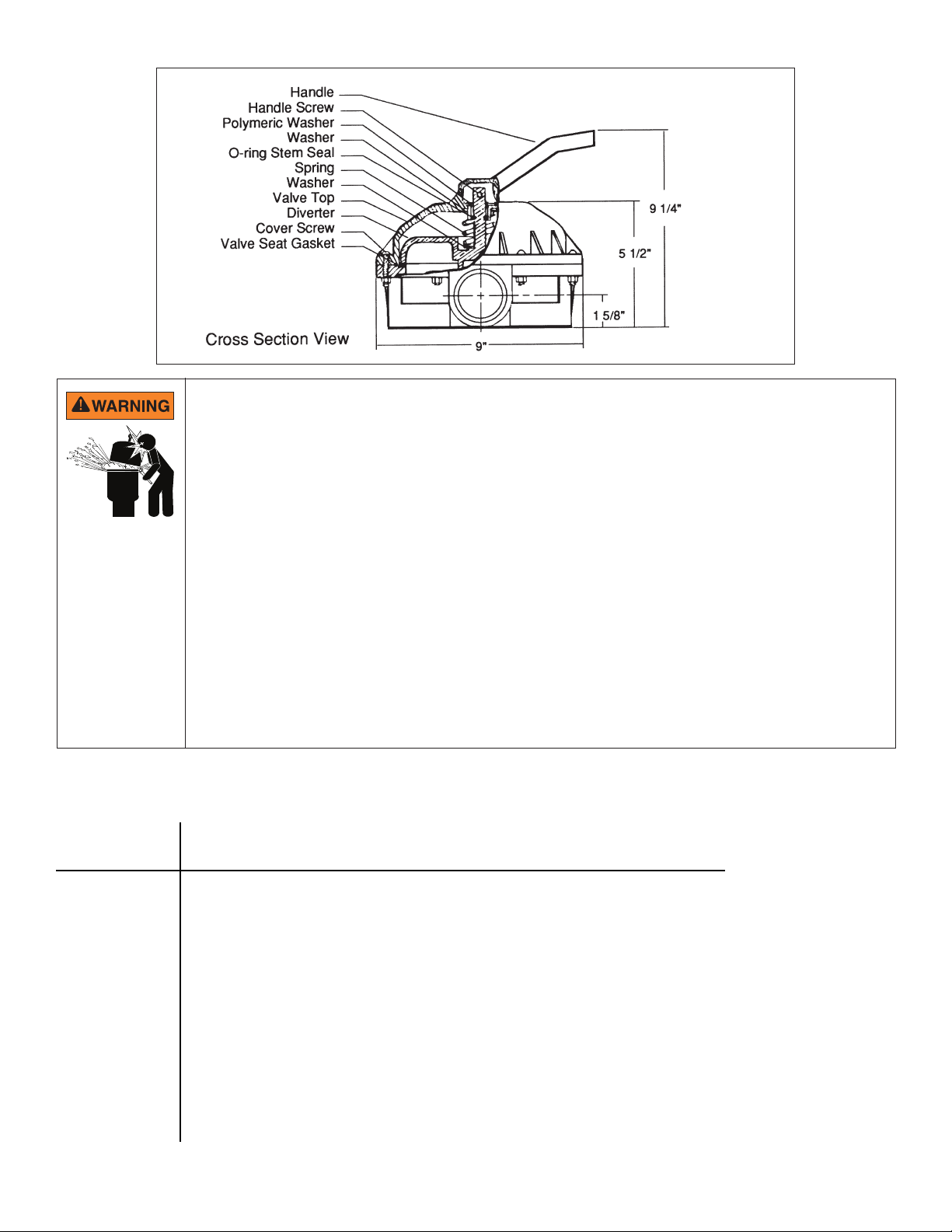
FILTER OPERATES UNDER HIGH PRESSURE.
When any part of the circulating system, (e.g., clamp, pump, filter, valve(s), etc.), is serviced, air can enter the
system and become pressurized. Pressurized air can cause the lid to separate which can result in severe injury,
death, or property damage. To avoid this potential hazard, follow these instructions:
1. Before repositioning valve(s) and before beginning the assembly, disassembly, or adjustment of
the clamp or any other service of the circulating system: (A) Turn the pump OFF and shut OFF any
automatic controls to ensure the system is NOT inadvertently started during the servicing; (B) open the
manual air relief valve; (C) wait until all pressure is relieved.
2. Whenever installing the filter clamp FOLLOW THE FILTER CLAMP INSTALLATION INSTRUCTIONS
EXACTLY.
3. Once service on the circulating system is complete FOLLOW SYSTEM RESTART INSTRUCTIONS
EXACTLY.
4. Maintain circulation system properly. Replace worn or damaged parts immediately, [e.g., clamp,
pressure gauge, valve(s), o-rings, etc].
5. Be sure that the filter is properly mounted and positioned according to instructions provided.
Valve Positions Overview
FLOW PATH
SETTING Function
Filter Pump > Sand Top / DE Bottom > Through Filter > DE Top / Sand Bottom > Return
For normal filter action and vacuuming pool thru filter.
Backwash Pump > DE Top / Sand Bottom > Through Filter > Sand Top / DE Bottom > Waste
For cleaning filter by reversing flow
Rinse Pump > DE Top / Sand Bottom > Through Filter > DE Top / Sand Bottom > Waste
For start-up cleaning and resetting filter bed after backwashing
Waste Pump > Waste
For vacuuming directly to waste, lowering pool level or draining pool
Closed No Circulation - DO NOT USE THIS SETTING WITH PUMP OPERATING!
Recirculate Pump > Return
For circulating water without going through filter
HI-FLOW™ Side Mounted Backwash Valve Installation and User's Guide
Page 3

Valve Installation
This valve is available in two models for use with sand type or diatomaceous earth (DE) type pool filters. Be
sure that you have the correct model for your filter. Installing the incorrect model may cause your pump to
dead head, or drain the pool when in backwash position.
1. Confirm correct valve is being used; DE valves for DE filters and Sand valves for Sand filters.
2. Install valve to filter by securing bulkhead nuts on valve to fittings on the filter.
Tighten the nuts by hand only! No additional tightness is required.
3. Plumb pump piping to center pipe in valve.
4. Plumb return and waste lines.
Winterizing
1. Drain and winterize pump and filter per manufacturer's instructions.
2. Depress valve handle and rotate so pointer on handle is between any two settings.
Replacement of Valve Top and Diverter Assembly
1. Set valve handle in any setting.
2. Remove cover screws.
3. Lift off valve top and diverter assembly.
4. Install new valve top and diverter assembly. Be sure arrows on valve top and bottom are aligned.
5. Tighten cover screws evenly and alternately. Do not over tighten.
3
Complete Disassembly
1. Remove Handle to diverter screw. Note arrow on top of diverter stem as handle is removed.
2. Evenly and alternately loosen cover screws.
Top is under spring load. Loosen all screws before removing any of them.
3. Remove cover screws and valve top.
4. Note location of O-ring and spring, and number of washers on diverter stem. Remove O-Ring, spring and washers.
5. Re-assemble in reverse order.
Note: Prior to assembly, be sure bottom gasket and diverter sealing surface are clean and free from nicks to insure
positive sealing.
6. When replacing valve handle, be sure arrow on diverter stem and pointer on handle are pointed in the same direction.
DO NOT over tighten the screws or use motorized screwdrivers; as this can cause damage to the threads.
HI-FLOW™ Side Mounted Backwash Valve Installation and User's Guide
Page 4

4
Technical Data
Replacement Parts
12
11
Covers Assemblies P/Ns 261049, 261050 and 261142
Item P/N Description Qty.
1
2
3
4
5
6
7
5
8
9
1 272520 Handle 1
2 272405 Screw - Handle 1
3 272402 Washer, Plastic 1
4 272412 Valve Top 1
5 271193 Washer - 18 GA 2
6 272400 Spring - Compression 1
7 272406 O-ring - Diverter 1
8 272413Z Diverter 1
9 272409 Seal -Diverter 1
10 98211400 Nut - 1/4" - 20 Hex 8
11 272415 Plat - 2" Valve Bottom 1
12 272403 Screw - 1/4" - 20 8
* 272422 Valve Top Assembly 1
*This part number includes items 1 thru 9
10
Note: When replacing gasket P/N 272409, secure it
to valve bottom with an instant cyanocrylate adhesive
suitable for bonding rubber to plastic.
Head Loss Curves
HiFlow 2” Valve Head Loss Curve
35
30
O)
2
25
20
15
10
Total Head Loss (FT of H
5
0
0 20 40 60 80 100 120 140
Filter Mode
Flow Rate (GPM)
HiFlow 2” Valve Head Loss Curve
35
30
O)
2
25
20
15
10
Total Head Loss (FT of H
5
0
0 20 40 60 80 100 120 140
Backwash Mode
Flow Rate (GPM)
1620 HAWKINS AVE., SANFORD, NC 27330 • (919) 566-8000
10951 WEST LOS ANGELES AVE., MOORPARK, CA 93021 • (805) 553-5000
WWW.PENTAIR.COM
All Pentair trademarks and logos are owned by Pentair or one of its global aliates. Hi-Flow™ is a trademark of Pentair Water Pool and Spa, Inc. and/or its aliated
companies in the United States and/ or other countries. Unless expressly noted, names and brands of third parties that may be used in this document are not used
to indicate an aliation or endorsement between the owners of these names and brands and Pentair Water Pool and Spa, Inc. Those names and brands may be
the trademarks or registered trademarks of those third parties. Because we are continuously improving our products and services, Pentair reserves the right to
change specications without prior notice. Pentair is an equal opportunity employer.
© 2018 Pentair Water Pool and Spa, Inc. All rights reserved. This document is subject to change without notice.
P/N 272133 REV. G 11/28/18
 Loading...