

Page 1
HBM200/HBMX200* SERIES
*For use in Hazardous Locations Class I, Division 1, Groups C & D
SUBMERSIBLE BASIN MIXER
INSTALLATION AND SERVICE MANUAL
NOTE! To the installer: Please make sure you provide this manual to the owner of the equip ment or to the responsible
party who maintains the system.
Item # E-03-545 | Part # 5625-545-1 | © 2014 Pentair Pump Group, Inc. | 09/05 /14
*
Page 2
General
WHITE W/BLACK STRIPE - P1
BLUE - P2
ORANGE - SEAL PROBE
SENSOR LEADS
MOTOR LEADS
(YELLOW) (BLACK) (LAVENDER)
WHITE W/BLACK STRIPE - P1
BLUE - P2
ORANGE - SEAL PROBE
SENSOR LEADS
MOTOR LEADS
ORANGE - SEAL PROBE
Information
Attention:
This manual contains important
information for the safe use of
this product. Read this manual
completely before using this
product and refer to it often for
continued safe product use. Do
not throw away this manual. Keep
it in a safe place so that you may
refer to it often.
Reasonable care and safe methods
should be practiced. Check the
local codes and requirements
before installation.
WARNING: Before handling
electrical equipment, always
disconnect the power first. Do not
smoke or use sparkable electrical
devices or flames in a septic
(gaseous) or possible septic sump.
CALIFORNIA PROPOSITION
65 WARNING:
This product
and related accessories contain
chemicals known to the State of
California to cause cancer, birth
defects or other reproductive harm.
CAUTION: To reduce risk of
electrical shock, do not remove
cord or strain relief. Do not
connect conduit to mixer.
Electrical installations shall be
in accordance with the National
Electrical Code and all applicable
local codes and ordinances.
For use with maximum
140°F water.
Septic tank should be vented in
accordance with local plumbing
codes and should not be installed
in locations classified as
hazardous, in accordance with the
National Electrical Code, ANSI/
NFPA 70-1999.
2
WARNING: Severe injury may
result from accidental contact
with moving propeller. Keep
clothing, hands and feet away
from propeller any time power is
connected to the mixer.
The Mixer
Description:
The integral stainless steel motor
shaft is sealed by two mechanical
seals with an oil chamber between
the seals to provide lubrication
for both seal faces.
Two ball bearings are used to
handle the loads. The upper
bearing takes radial load, while
the larger lower bearing handles
both thrust and radial loads.
Both bearings are permanently
lubricated by the dielectric oil in
the motor housing. The motor is
fixed within the motor housing
and is completely submerged in
the dielectric oil for maximum
heat transfer. The motor housing
and seal chamber are completely
sealed with O-rings located at
mating part faces.
The power cord entry system is
designed to give double sealing.
The chamfered pilot of the motor
housing mates with the molded
cord end to form the first seal.
The cord grip forms the second
seal around the molded cord end
and provides strain relief. The
cable includes the leads for both
heat sensors (motor protection)
and the seal sensor lead for seal
leakage detection.
Application:
The submersible basin mixer is
used to break up crusts and solids
that float at the top of a solids
handling basin. The unit can also
be used for mixing and stirring
applications in industrial areas
and waste management facilities.
Mixer Installation
Unpacking:
Remove from carton. When
un pack ing unit, check for
concealed damage. Claims
for damage must be made at
the receiving end through the
delivery carrier. Dam age cannot
be processed from the factory.
Location:
If mixers are installed in an
existing basin or concrete sump,
they may either be connected
permanently or rails and brackets
can be fur nished for mounting
to walls of basin. The complete
factory built packaged system
is recommended for the most
satisfactory in stalla tion and
generally for the low est cost
where expensive in stalla tion
labor is involved.
SENSOR LEADS
WHITE W/BLACK STRIPE - P1
BLUE - P2
230V (DUAL VOLTAGE) THREE PHASE
WHITE
(BLUE) (TAN) (ORANGE)
(YELLOW) (BLACK) (LAVENDER)
460V (DUAL VOLTAGE) THREE PHASE
(BLUE) (TAN) (ORANGE)
T7
(PINK)
BLACK
L1
T1 T2 T3
T7
T4
WHITE
T1 T2 T3
T4
L2
T8 T9
(PINK) (RED) (LT. BROWN)
T5 T6
BLACK
L1
T8 T9
(RED)
T5 T6
L2
(LT. BROWN)
RED
L3
RED
L3
P1 (PURPLE)
P2 (DARK BROWN)
PL (PURPLE)
P2 (DARK BROWN)
Page 3

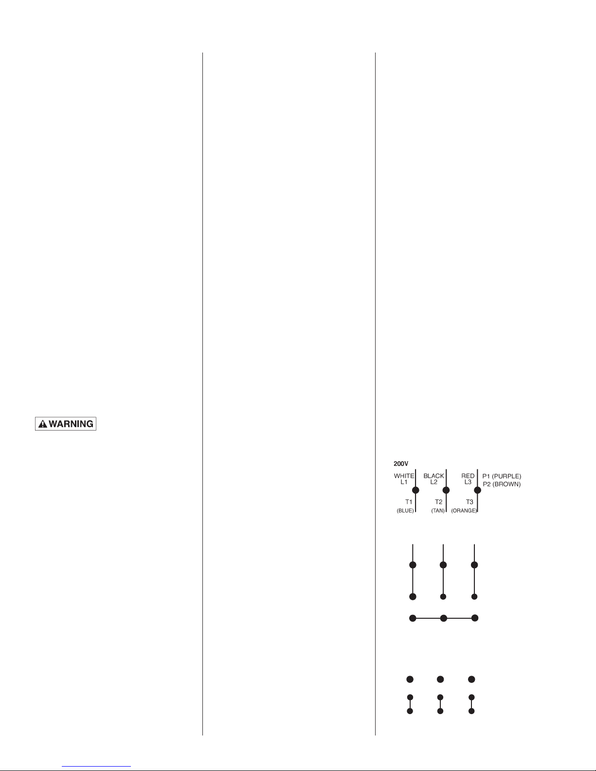
Electrical Connections:
Make all connections from motor
to control panel to com ply with
local codes.
NOTE: Hydromatic
control panels supply the correct
circuitry for moisture and heat
sensor connections. Failure
to install the correct circuitry
with proper connection would
negate warranty and factory
mutual approval.
CAUTION: Make sure that
the ground wire is securely
connected and that the unit is
properly grounded in accordance
with local codes.
®
built
Mixer Operations
Starting the Mixer:
WARNING: Severe injury may
result from accidental contact
with moving propeller. Keep
clothing, hands and feet away
from propeller any time power is
connected to the unit.
To start the mixer, perform the
following steps in order:
If mixer is three phase, the
rotation of the propeller must
first be checked. Lift mixer from
sump, lay it down, and quickly
turn on and then off.
The propeller should turn
counterclockwise when viewed
from the suction. If rotation is
wrong, turn off main breaker and
interchange any two line leads to
motor to correct rotation. If mixer
is single phase, no rotation check
is necessary.
After installing mixer in basin in
desired location, run water into
basin until mixer is covered.
Turn mixer on and observe
mixing action at the surface of
the water. If required, adjust
position of mixer mounting
brackets until desired mixing
action is achieved in the basin.
If problems occur check the
power source. Make sure a
separate supply line is available.
Verify the voltage supply.
Mixer
Maintenance
Disassembly, Inspection,
Reassembly:
For Hazardous Location Service:
These pumps are to be used for
handling sewage, wastewater
and storm water only. Do not
use in other hazardous locations.
These motors must be repaired
and serviced only at Hydromatic
authorized service centers or at
the factory. Any unauthorized
field repair voids the warranty
and the hazardous location rating.
Turn off circuit break er.
Remove mixer from sump.
Replacing Seals:
Drain the oil in the seal cham ber
by removing the drain plug on
the side of the unit. If it con tains
water, the lower seal has failed
and should be replaced. The
mo tor hous ing should be drained
and the upper seal replaced if
the lower seal has failed, since
foreign material in the seal
chamber may have dam aged the
upper seal.
Remove the propeller after first
removing center set screw at the
end of the motor shaft.
Using a pair of snap ring pliers,
remove the snap ring that secures
the lower seal. Remove the lower
seal rotating elements by sliding
the spring off the shaft. Then
using two screwdrivers, slide the
carbon assembly off by prying on
the retaining ring.
Loosen and remove the cap
screws that hold on the seal
housing, then re move the seal
housing. Using a socket that will
fit onto the back of the seal, tap
the sta tion ary seal assembly out
of the seal housing.
Using a pair of snap ring pliers,
remove the snap ring that secures
the up per seal. Remove the spring
retainer and spring from the shaft,
and using the same method as
used for the lower seal, remove
the carbon seal assembly.
With a pair of screwdrivers, pry
up on the seal/bearing plate.
®
Remove the seal/bearing plate
until you have access to the
seal sensor wire, then carefully
pull the seal sensor wire off the
seal probe which will allow the
complete removal of the seal/
bearing plate.
Take a socket and tap out the
stationary portion of the seal from
the seal/bearing plate in the same
manner as used for the lower
stationary seal.
After checking both of the
O-rings, replace the seal bearing
plate in the motor housing,
making sure that the seal sensor
wire has been reattached to the
seal probe. Use O-ring lube to
prevent cutting in assembly.
Take the sta tion ary portion of
the new seal, and lube the rubber
material with a good quality
dielectric oil. Press the stationary
portion of the new seal into the
seal/bearing plate.
CAUTION: Do not reuse old seal
parts. Replace all parts with new.
Mixing old and new parts could
cause im me di ate seal failure.
3
Page 4

Using a good quality dielectric
oil, lube the rubber material on
the carbon seal assembly and
press it on the shaft. Place the
spring and the seal retainer on
the shaft as removed. Replace the
snap ring.
Carefully place the seal housing
onto the seal bearing plate,
re place the cap screws, and
evenly tighten.
Troubleshooting
Below is a list of troubles and
their probable causes:
Insufficient mixing
1. Mixer orientation
needs adjusted
2. Wrong rotation
3. Speed too low
Using a pressure gauge with a
fill stem, pres sur ize the motor
housing to no more than 7 psi
with dried air and check for
leaks. If after several minutes the
gauge reads the same, the seal
is good and you can con tin ue
with assembly.
NOTE: It is normal to observe
some air bubbles in the seal area
initially as the seal seats. If the
bubbles do not stop within a few
seconds, the seal is either not
properly installed or is damaged.
Following the same procedure
outlined previously to install the
lower seal assembly. Re place
the impeller using a re mov able
locking adhesive.
Reassemble the propeller set
screw onto mixer.
Mixer overloads motor
1. Wrong rotation
2. Specific gravity or vis cos i ty
of liquid too high
3. Speed too high
4. Mixer clogged
5. Defective bearings
Mixer is noisy
1. Defective bearings
2. No axial clearance be tween
propeller and seal housing
Refill all cham bers with a good
quality di elec tric oil. Fill the
motor housing so that the tops
of the motor windings have been
covered (2500 ml), but leave an
air gap to allow for ex pan sion of
the oil. Fill the seal chamber with
700 ml of oil so that an air gap
also exists.
4
Page 5
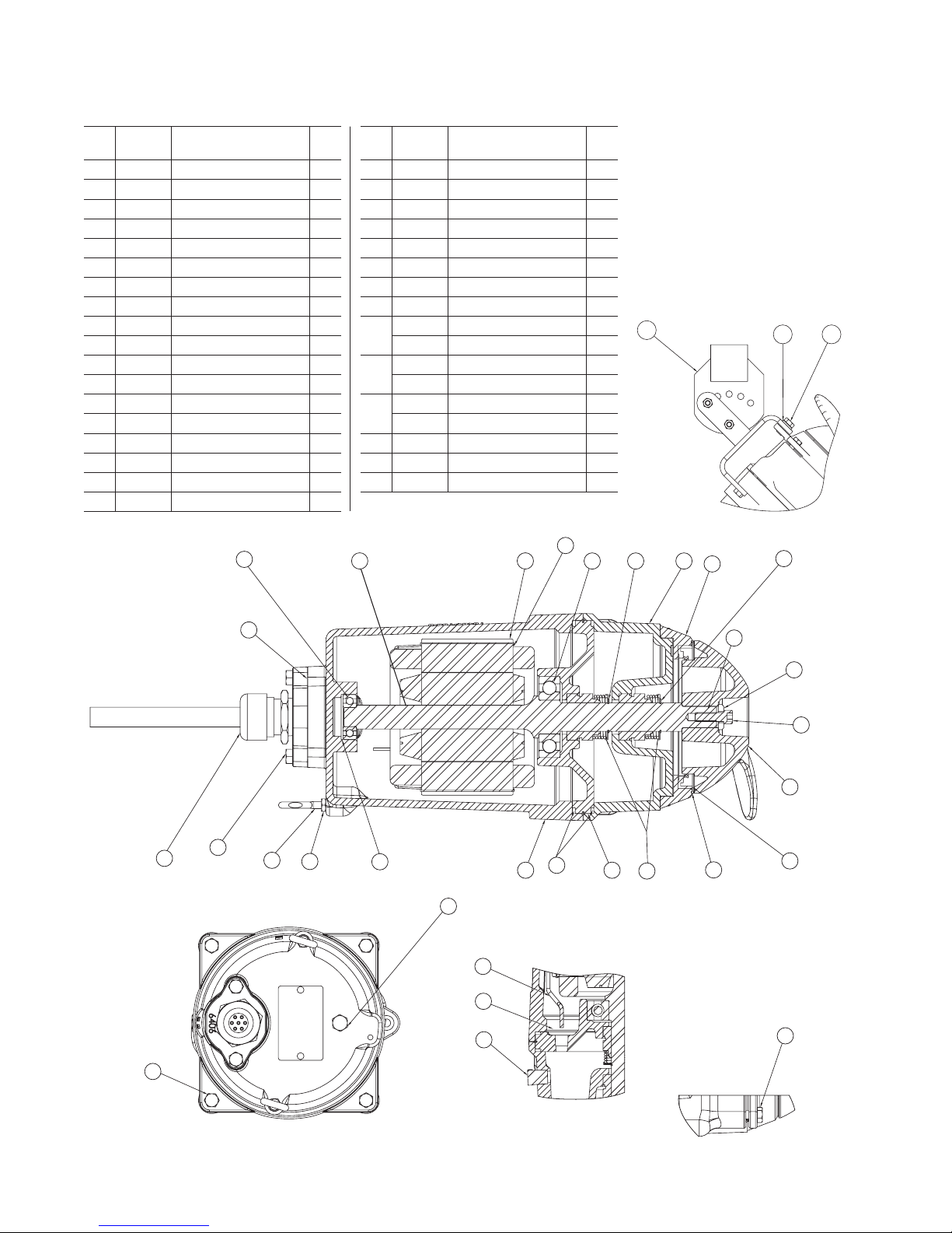
HBM200 Parts List
Item Eng. No.
1 144240115 Cord Assembly 1
2 000640011 Spring – Bearing Adj. 1
3 000650011 Bearing – Ball (Upper) 1
4 000650271 Bearing – Ball (Lower) 1
5 001010111 Screw – HHC 5/16-18 x 1-3/4 4
6 101020011 Key 1
7 003000001 Seal – Shaft 1" 2
8 005890101 Bolt – Eye 1/4-20 2
9 008340151 O-ring 3/32 Dia. 1.737 I.D. 1
10 009750021 Ring – Retaining 2
11 05022A092 Plug-Pipe 1/4 2
12 05876A120 O-ring 1/8 Dia. 6-1/4 I.D. 2
13 060000141 Wire w/Terminal 14 Ga Red 1
14 084720015 Seal Failure Ass’y 1
15 134880002 Plate/Bearing Seal 1
16 134890012 Housing – Seal 1
17 134893002 Housing – Lip Seal 1
18 134941002 Housing – Motor 1
Description Qty.
3
Part
Item Eng. No.
19 152120002 Propeller – Mixer 1
20 152220001 Seal – Lip 4" 1
21 19100A004 Screw – Cap 5/16 SST x 3/4 2
22 19100A029 Screw – Cap 5/16 SST x 1 4
23 001780041 Screw – Cap 5/16 SST x 1 1
24 19109A077 Nut – Hex 1/4 2
25 005190001 Washer 1
26 27755A000 Teflon Ring Seal 1
27 001450291 Stator bolt, 1750 rpm 4
001450101 Stator bolt, 1150 rpm 4
28 152150111 Rotor & Shaft 1750 rpm 1
152230111 Rotor & Shaft 1150 rpm 1
29 152150031 Stator 1750 rpm 1
152230031 Stator 1150 rpm 1
30 526033035 Bracket - Lower Mixer 1
31 05454A015 Washer – Lock SST 3/8 1
32 19101A003 Screw – Cap 3/8-16 1
28
Description Qty.
29
Part
30
27
10
4
16
17
31 32
10
9
1
5
21
8
24
2
11
13
14
11
12
18
15
7
6
25
23
19
26
20
22
Page 6
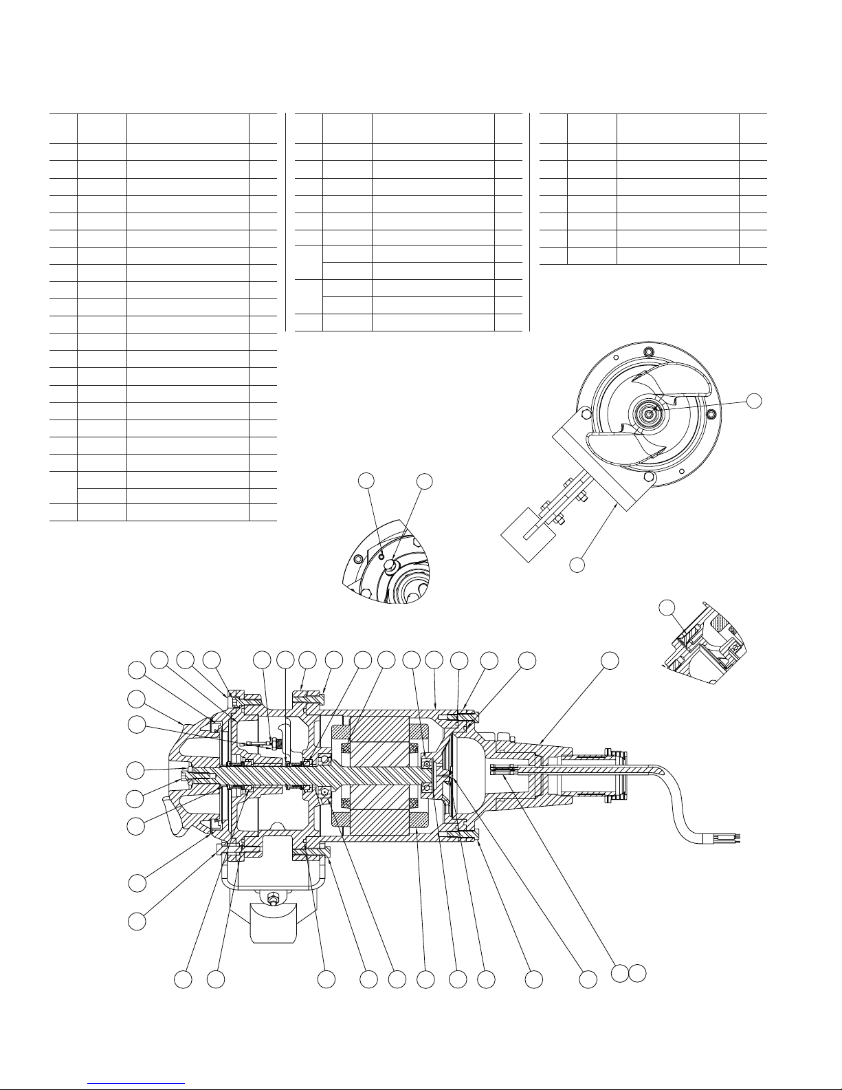
HBMX200 Parts List
22
33
4
29
25
14
30
15
77
8
26
10
18
23
13
28
24
17
16156
9
11
22
33
33
4
30
1
11
Item Eng. No.
1 22407C607 Cord Cap – 35 Ft. 1
05013A027
2
05022A092
3
05434A043
4
05876A122
5
05876A123
6
05876A125
7
06107A015
8
07597A017
9
12558A006
10
11 12672A002 Connector – Butt 22-16 2
12 19100A012 Screw – HHC 5/16-18 x 1-1/4 8
13 19100A033 Screw – Cap 5/16 X 7/8 8
14 19101A017 Screw – Cap 3/8-16 X 1-1/4 2
15 19331A005 Washer – Spring 2
16 21570B100X Cap – Upper Bearing 1
17 21571D100X Housing – Motor 1
18 21574D100X Housing – Upper Seal 1
19 21577A000 Plug – Special 1/2 Hex 1
20 21578C100X Housing – Lower Seal 1
22579A000 Ferrule – Rubber .312 O.D. X .265 I.D. 1
21 27799A000 Spacer – Propeller 1
Description Qty.
Screw – Set 5/16-18
Plug – Pipe 1/4
Screw – Machine 10-24 X 3/8
O-ring
O-ring
O-ring
Washer – Lock
Screw – Machine 5/16-18 X 1
Ring – Retaining
Part
2
2
1
1
1
2
1
2
1
Item Eng. No.
22 526033065 Bracket – Mixer 1
23 21576A010 Seal – 7/8" 2
24 08565A013 Bearing – Ball 1
25 08565A018 Bearing – Ball 1
26 22578A003 Electrode – with Resistor 1
27 001010111 Screw – HHC 5/16 – 18UNC x 1-3/4 2
28 152260111 Rotor/Shaft – 1750 rpm 1
152270111 Rotor/Shaft – 1150 rpm 1
29 152260031 Stator – 1750 rpm 1
152270031 Stator – 1150 rpm 1
30 12672A001 Connector 3
Description Qty.
2
3
Part
Item Eng. No.
31 001780041 Screw – Cap 5/16-18 1
32 005190001 Washer – Propeller 1
33 101020011 Key 3/16 Sq. X .69 1
34 134894002 Housing – Lip Seal 1
35 152220001 Lip Seal 1
36 152120002 Propeller 1
37 27755A000 Ring – Propeller 1
Description Qty.
33
Part
22
20
35
34 12
26
18
10
13
28
23
17
24
16
56
1
9
36
19
32
31
21
37
27
23 13
6
6
11
14
77
25
15
29
8
30
4
Page 7

THIS PAGE INTENTIONALLY LEFT BLANK
Page 8

STANDARD LIMITED WARRANTY
Pentair Hydromatic® warrants its products against defects in material and workmanship for a period of 12 months
from the date of shipment from Pentair Hydromatic or 18 months from the manufacturing date, whichever
occurs first – provided that such products are used in compliance with the requirements of the Pentair Hydromatic
catalog and technical manuals for use in pumping raw sewage, municipal wastewater or similar, abrasive-free,
noncorrosive liquids.
During the warranty period and subject to the conditions set forth, Pentair Hydromatic, at its discretion, will repair
or replace to the original user, the parts that prove defective in materials and workmanship. Pentair Hydromatic
reserves the right to change or improve its products or any portions thereof without being obligated to provide such
a change or improvement for prior sold and/or shipped units.
Start-up reports and electrical schematics may be required to support warranty claims. Submit at the time of start up
through the Pentair Hydromatic website: http://forms.pentairliterature.com/startupform/startupform.asp?type=h.
Warranty is effective only if Pentair Hydromatic authorized control panels are used. All seal fail and heat sensing
devices must be hooked up, functional and monitored or this warranty will be void. Pentair Hydromatic will cover
only the lower seal and labor thereof for all dual seal pumps. Under no circumstance will Pentair Hydromatic be
responsible for the cost of field labor, travel expenses, rented equipment, removal/reinstallation costs or freight
expenses to and from the factory or an authorized Pentair Hydromatic service facility.
This limited warranty will not apply: (a) to defects or malfunctions resulting from failure to properly install, operate or
maintain the unit in accordance with the printed instructions provided; (b) to failures resulting from abuse, accident
or negligence; (c) to normal maintenance services and parts used in connection with such service; (d) to units that
are not installed in accordance with applicable local codes, ordinances and good trade practices; (e) if the unit is
moved from its original installation location; (f) if unit is used for purposes other than for what it is designed and
manufactured; (g) to any unit that has been repaired or altered by anyone other than Pentair Hydromatic or an
authorized Pentair Hydromatic service provider; (h) to any unit that has been repaired using non factory specified/
OEM parts.
Warranty Exclusions: PENTAIR HYDROMATIC MAKES NO EXPRESS OR IMPLIED WARRANTIES THAT EXTEND
BEYOND THE DESCRIPTION ON THE FACE HEREOF. PENTAIR HYDROMATIC SPECIFICALLY DISCLAIMS THE
IMPLIED WARRANTIES OF MERCHANTABILITY AND FITNESS FOR ANY PARTICULAR PURPOSE.
Liability Limitation: IN NO EVENT SHALL PENTAIR HYDROMATIC BE LIABLE OR RESPONSIBLE FOR
CONSEQUENTIAL, INCIDENTAL OR SPECIAL DAMAGES RESULTING FROM OR RELATED IN ANY MANNER TO
ANY PENTAIR HYDROMATIC PRODUCT OR PARTS THEREOF. PERSONAL INJURY AND/OR PROPERTY DAMAGE
MAY RESULT FROM IMPROPER INSTALLATION. PENTAIR HYDROMATIC DISCLAIMS ALL LIABILITY, INCLUDING
LIABILITY UNDER THIS WARRANTY, FOR IMPROPER INSTALLATION. PENTAIR HYDROMATIC RECOMMENDS
INSTALLATION BY PROFESSIONALS.
Some states do not permit some or all of the above warranty limitations or the exclusion or limitation of incidental or
consequential damages and therefore such limitations may not apply to you. No warranties or representations at any
time made by any representatives of Pentair Hydromatic shall vary or expand the provision hereof.
740 EAST 9TH STREET 490 PINEBUSH ROAD, U NIT #4
ASHLAND, OHIO, USA 44805 CAMBRIDGE, ONTARIO, CANADA N1T 0A5
419-289-1144 800-363-PUMP
WWW.HYDROMATIC.COM
Warranty Rev. 12/13
Page 9

MODELS HBM200/HBMX200
BASIN MIXER CONTROL PANEL
INSTALLATION AND SERVICE MANUAL
NOTE! To the installer: Please make sure you provide this manual to the owner of the equip ment or to the responsible
party who maintains the system.
Item # E-03-520 | Part # 5625-520-1 | © 2012 Pentair Pump Group, Inc. | 11/05/12
Page 10

General
Information
Thank you for purchasing your
Hydromatic® Basin Mixer Control
Panel. To help ensure years of
trouble-free operation, please read
the following manual carefully.
Before Operation:
Read the following in structions
care ful ly. Reasonable care
and safe meth ods should be
practiced. Check local codes and
requirements before installation.
Attention:
This manual contains important
information for the safe use of
this product. Read this manual
completely before using this
product and refer to it often
for con tin ued safe product use.
DO NOT THROW AWAY OR
LOSE THIS MAN U AL. Keep
it in a safe place so that you may
refer to it often.
Unpacking Panel:
Remove panel from carton.
When un pack ing unit, check
for concealed damage. Claims
for damage must be made at
the receiving end through the
delivery carrier. Damage cannot
be processed from the factory.
CALIFORNIA PROPOSITION
65 WARNING:
This product and
related accessories contain
chemicals known to the State of
California to cause cancer, birth
defects or other reproductive
harm.
Power
Supply
WARNING: Do not attempt to
wire this control box unless you
have a good working knowledge
of electricity and are familiar
with the state and local codes. If
you are in doubt about anything,
contact a qualified electrician.
Do not attempt to operate this
unit on any other voltage or
power distribution other than
for which it was originally
designed (check nameplate).
Failure to comply with this
will result in the immediate
cancellation of all warranties
and claims.
It is advisable to put the panel
on its own circuit using a circuit
breaker adequately sized to protect
the mixer. Check state and local
codes for the correct wire size and
circuit protection to use. The wire
should be sized large enough to
handle the full load current of the
mixer you are operating and any
voltage drop that might occur due
to long service runs.
Run power supply lines to the
control box and secure (knockouts
are not supplied in this box).
Select a convenient location on
the bottom to enter the box with
the power supply. Cut a hole with
a chassis punch. Caution should
be taken not to get metal chips
in the components while cutting
hole. After the hole is cut, any
metal particles must be removed
from the box. Failure to do so may
result in premature component
failure.
the bottom right of the box. The
ground lug should be fastened to
a good driven earth ground by
one of the methods described in
the National Electric Code. NEC
does not permit using ground
as a current-carrying conductor,
therefore a neutral must be
provided for 115 volt 1 phase, 208
volt 1 phase, 230 volt 1 phase, or
208 volt 3 phase systems.
WARNING: Before handling
these mixers and controls,
always disconnect the power
first. Do not smoke or use
sparkable electrical devices or
flames in a septic (gaseous) or
possible septic sump.
Electrical Connections:
The contractor must conform
to the latest requirements of the
National Electrical Code. All
conduit and ca bles shall be in
accordance with NEC Code
NFPA #70. To maintain UL and
CSA ENCL rating, use the same
type UL and CSA weatherproof
con duit hubs when connecting to
this en clo sure. Prior to conducting
any in stal la tion, repair or service
with re gard to the control panel,
refer to the schematic appropriate
for that panel. The schematic will
provide guidance with regard to
the terminal block con nec tions.
CAUTION: A nonmetallic
enclosure does not provide
grounding conduit con nec tions.
Use grounding bush ing and
jumper wires.
Make the Following
Electrical Con nec tions:
a. Connect the mixer leads to the
control panel.
2
Connect incoming power to the
terminal blocks per the included
schematic and all necessary
ground wires to the ground lug at
b. Connect the mixer heat sensor
and seal failure leads (if
available on the mixer) to the
Page 11

appropriate ter mi nal blocks in
the control panel.
HBM (Pre December 2011)
c. Before connecting power to
the control panel, make sure all
con trol switches (e.g. H-O-A
switch) and protective devices
(e.g. breakers) are in the Off
po si tion. Now connect power
to the terminal block or the
circuit break er as directed by
the sche mat ic.
d. Control panel must be
grounded properly per
NEC and/or local codes. To
facilitate this, a ground lug is
provided on the control panel.
HBM (Pre December 2011)
Terminal Mixer Wire Color Function
M1 White Mixer Power
M2 Black Mixer Power
M3 Red Mixer Power
G Green Ground
1 Orange Seal Leak Sensor
2 Blue Heat Sensor
3 White w/Black Stripe Sensor Common Wire
1
2
3
Mixer Seal Leak and
Heat Sensor Terminals
M1
Mixer Motor
Power Terminals
M2
M3
Incoming Power
HBM (Post December 2011)
L1
Terminals
L2
L3
Ground
HBM (Post December 2011)
Terminal Mixer Wire Color Function
T1 White Mixer Power
T2 Black Mixer Power
T3 Red Mixer Power
G Green Ground
S1 Orange Seal Leak Sensor
H1 Blue Heat Sensor
H2 White w/Black Stripe Sensor Common Wire
HBMX (Post December 2011)
Terminal Mixer Wire Color Function
T1 White Mixer Power
T2 Black Mixer Power
T3 Red Mixer Power
G Green Ground
S1 Red Seal Leak Sensor
S2 Orange Seal Leak Sensor
H1 Black Heat Sensor
H2 White/Blue Tracer Heat Sensor
HBMX (Post December 2011)
3
Page 12

Start-up
Operation
on hit the Menu button
until the pointer is above
main menu.
iii. Set 1-29 AMT; set to 2
and follow instructions
then set back to 0.
1. Check junction box for
moisture. Moisture may cause
chattering of relays/contactors.
2. WARNING! Live voltage
can kill! Check incoming
power volt age to make sure
that it is correct for panel
and mixer model.
3. Energize control panel. (Turn
on power to panel.)
4. WARNING! Live voltage
can kill! Check voltage to the
panel and at secondary of
control trans form er using a
voltmeter. If no transformer
is supplied, check volt age at
the circuit breakers.
5. Set the application specific
parameters for the VFD.
a. With power to the VFD
and the H-O-A switch in
the Off position, power
Mixer Model Amps Speed Voltage
HBM200M6-4/HBMX200DC 8 1750 200
HBM200M3-4/HBMX200EC 7 1750 230
HBM200M4-4/HBMX200FC 3.5 1750 460
HBM200M6-6/HMBX200DB 5.5 1150 200
HBM200M3-6/HBMX200EB 4.8 1150 230
HBM200M4-6/HBMX200FB 2.4 1150 460
Speed charts – FOR REFERENCE ONLY.
4
b. Use up and down key to
switch parameter groups.
Hit OK to set a parameter
group.
c. Use up and down key to
switch parameters. Hit OK
to set a parameter group.
Use up and down key to
change parameters. After
each change hit OK again
to set the value.
d. Use the back button to
get back to the parameter
groups.
e. Parameters to be set at
installation:
i. Set 1-24 motor current;
see chart below.
ii. Set 1-25 motor nominal
speed; 1150 or 1750;
see chart below.
iv. Set 3-02 speed in Hz;
30–60 Hz.
f. Hit auto on button and
move H-O-A switch to
Auto position. When timer
contact is closed motor
should run.
WARNING: Do not exceed
60 Hz or go below 30 Hz.
Exceeding 60 Hz will draw
more horsepower from the
motor than it was designed for.
Running at lower than 30 Hz
may not supply enough starting
torque to the mixer unit.
6. With H-O-A switch in Hand,
check mixer to ver i fy the
mixer is run ning. On three
phase power, check to see if
each mixer has prop er ro tation.
7. Check full load current with
amp probe and compare it
with the name plate rat ing.
On three phase mixers, check
all three phases. Use a true
RMS meter to obtain accurate
readings.
8. Set range and adjustment
settings on timer.
a. Select one of the 16 built-in
time ranges by setting the
rotary switch per a chart on
Page 13

“On Time” adjustment
within range selected
“Off Time” adjustment
within range selected
ON TIME
MIN MAX
MIN MAX
OFF TIME
I
HJ
GK
FL
EM
DN
CO
BP
A
A
PB
OC
ND
ME
LF
KG
JH
I
“On Time”
range selection
Example dial positions
On Time
Off Time ~ 18 sec
“Off Time”
range selection
shown:
~
10 sec
Dial Setting Timing Range
A 0.6 – 2.5 Sec.
B 1.5 – 5 Sec.
C 2.5 – 10.5 Sec.
D 5 – 21 Sec.
E 10 – 42 Sec.
F 0.4 – 1.4 Min.
the unit and adjust within
that range using the knob
on top.
9. With H-O-A switch in Auto,
check timer op er a tion. For
sequence of op er a tion, refer to
design specification.
10. Make sure H-O-A switch is
left in the Auto position after
start-up is completed.
Mixer Start-Up:
Refer to mixer Installation and
Service Manual.
Mixer
Maintenance
WARNING: Before handling
these mixers and controls,
always dis con nect the power
first. Do not smoke or use
sparkable electrical devices or
flames in a septic (gaseous) or
possible septic sump.
The maintenance schedule
will vary with operating and
Dial Setting Timing Range
G 0.7 – 2.8 Min.
H 1.5 – 5.5 Min.
I 3 – 11 Min.
J 5.5 – 22.5 Min.
K 11 – 45 Min.
environmental con di tions. It will
also vary with the specific type of
control supplied. The list herein is
a guide only.
1. Exercise breaker through
one cy cle. Be careful not to
overexercise as the breaker
is not a switch ing device.
Excessive operations tend to
affect the trip curve of the
breaker.
Programming with LCP12 keypad
The LCP is divided into four functional groups:
1. Numeric display
2. Menu key
3. Navigation keys
4. Operation keys and LEDS
1.
2.
3.
4.
Menu
On
Warn.
Alarm
Hand
On
Status Quick
k
c
a
B
OK
Off
Reset
Menu
Main
Menu
Auto
On
Dial Setting Timing Range
L 0.4 – 1.5 Hr.
M 0.8 – 3 Hr.
N 1.5 – 6 Hr.
O 3 – 12 Hr.
P 6 – 24 Hr.
2. Check relay for excessive
humming. This can be
accomplished by turning
mixer on and off in the Hand
mode with the H-O-A switch.
3. Check mixer run light by
running mixer in Hand mode.
Check bulb(s) in any other
light(s).
4. With the power off, check
con ti nu ity of all control fuses.
5. Check voltage at primary
and sec ond ary of control
transformer.
6. Check the mixer full load
amps.
7. Check junction boxes for
moisture. Moisture may
cause chattering of relays and
contactors.
8. Check for moisture inside
control panel enclosure.
Moisture can cause damage to
electrical com ponents. Check
door gasket for prop er seal.
5
Page 14

9. Check labels to verify they
have not been damaged.
10. Lubricate enclosure hinges.
Spare Parts List:
The following is a list of
recommended spare parts.
However, conditions of ser vice
vary significantly and a general
list may not in its entirety be
applicable to a given installation.
The user should ex er cise judgment
in defining specific re quire ments
based on this guide
1. Fuses for control transformer
primary and secondary. (If
required.)
2. VFD.
3. Bulbs for any light requiring
a bulb.
4. Control transformer. (If
required.)
5. Control and time delay relay.
(If required.)
.
Timer
Controls
Your control panel is equipped
with a repeat cycle time delay
relay (On time first followed by
Off time and repeating). The On
and Off times have rotary switch
selectable timing ranges and
adjustment knobs for selecting the
time withn that range. Select one
of the 16 built-in ranges by setting
the rotary switch per a chart on
the time delay relay and adjust
within that range using the
appropriate knob.
Seal
Failure
Your mixer is equipped with a
seal fail (moisture) sensor. The
presence of water energizes the
seal leak warning output. This
activates a warning light or alarm
only, and does not stop the motor.
It indicates a leak has occurred
and the mixer must be repaired.
For standard location mixers the
resistance across the moisture seal
(seal failure) probe and ground
wire should be checked after a
seal leak warning light has lit.
For hazardous location mixers
the resistance across the moisture
seal (seal failure) probes should
be checked after a seal warning
light has lit. This can be done
by disconnecting the control
wires from the control panel
and measuring the resistance
with an ohmmeter between the
wires. Refer to the control panel
schematic for wire identification.
For a standard, non-hazardous
location mixer the reading should
be 100,000 ohms or greater, and
for a hazardous location mixer the
reading should be above 33,000
ohms. If the measured values are
below those indicated above, then
the mixer may have a lower seal
failure and require service.
On control panels for hazardous
location applications the seal
leak test switch tests the seal leak
circuitry continuity. When pushed
the seal leak test bulb should light.
If the test bulb does not light, it
means either the wiring circuitry
to the seal leak probes has been
broken or the bulb has burned out.
Temperature
Failures
NOTE: Hydromatic® control
panels supply the correct
circuitry for moisture and heat
sensor connections.
Your mixer is equipped with
temperature fail sensor thermostats
attached directly to the motor
windings. The thermostats open if
the motor windings see excessive
heat and, in turn, open the motor
contactor in the control panel,
breaking the power to the mixer.
When the motor is stopped due
to an overheated condition, it will
not start until the motor has cooled
and the heat sensor reset button is
manually pushed on the front of
the control panel.
NOTE: Failure to use proper
circuitry and to connect the
motor overheat protection in the
control panel would negate all
warranties and Factory Mutual
Approval.
WARNING: Before handling
the mixer and controls, always
dis con nect the pow er first. Do
not smoke or use sparkable
electrical devices or flames in
a septic (gas eous) or possible
septic sump.
Troubleshooting
1. Mixer does not run in
Hand position.
a. Check mixer circuit breaker
and control fuse for trip ping
or blown condition.
b. Check incoming power
volt age and control cir cuit
volt age.
c. Check VFD to see if it is
tripped. Reset VFD if
tripped and check mixer
current with ammeter.
6
Page 15

d. With the power off, check
motor heat sensor continuity.
e. Check wiring of mixer to
con trol panel. It should
agree with the sche mat ic.
2. Mixer does not run in Auto
position.
a. Check items (a.) through
(e.) per Item #1 above.
b. Check knob settings on
timer to ensure proper
sequencing. Check both On
and Off time range selector
knobs as well as On and Off
time adjustment knobs.
c. If mixer does not run in
Auto mode, check Auto
circuit wiring in panel.
3. Mixer runs, but run light
does not energize.
a. Re move light and check
with an ohmmeter.
b. Check run light wir ing.
4. Severe humming/chat ter ing
of control relay.
a. There may be low voltage.
Check voltage at primary
and secondary of control
transformer us ing a
volt me ter. This low voltage
condition may cause severe
chat ter ing and burnout of
relay.
b. Relay may have dust around
magnet of coil struc ture.
Dry or clean as re quired.
c. Check voltage to the
control panel. Relays
require a minimum of
80% of full volt age to pull
in without chatter. If the
problem is a re cur ring
one, measure voltage with
recorder on a 24 hour basis.
d. Dry out the junction box
(if furnished); moisture
in the junction box may
cause relays to energize
intermittent ly.
5. Short cycling mixer.
a. Check timer controls.
6. Run light stays on.
a. Selector switch may be in
the Hand position.
7. Nuisance tripping of overload
on VFD or cir cuit break ers.
a. Check mixer amp draw with
amp probe and compare to
nameplate amps on mixer.
b. The propeller may be locked
up due to excessive debris
or solids.
c. Possible motor failure (fault
in windings).
d. Mixer may be miswired to
ter mi nal block.
e. Voltage and current
unbalance. Voltage
un balance on three
phase power sources can
cause motor current to
become un bal anced and
exces sive heating will
re sult. Trip ping of the
over load protection and
premature motor failures
can be expected if the
current unbalance exceeds
five percent.
Percent Maximum Current
Current = Difference from x 100
Unbalance Average Current
_______________
Average Current
To determine if motor current
un bal ance is a function of the
motor or the power supply:
1. Label the leads and the terminals
1, 2, and 3 respectively.
2. Record the amperage for each
lead.
3. Move each lead to the next
terminal (1 to 2, 2 to 3, 3 to 1).
4. Again read the amperage of
each lead.
5. Move each lead to the next
terminal (1 to 3, 2 to 1, 3 to 2).
6. Again read the amperage of
each lead.
7. If the unbalance moves with
the motor leads, the un bal ance
is caused by the mo tor. If the
unbalance remains with the
terminals, the un bal ance is in
the pow er supply.
8. If the current unbalance
exceeds five percent, nui sance
tripping or ex ces sive heating
will result.
9. Connect leads for the lowest
percent of current un bal ance.
Factory Set
Parameters for VFD
Parameters set at factory for 230V panels
1) Set 1-20 motor power 1.5 kW or 2 HP
2) Set 1-22 motor voltage 230 volts
3) Set 1-24 motor current 4.8 amps
4) Set 1-25 motor nominal speed 1150
5) Set 3-02 min. speed in Hz 30
6) Set 3-03 max. speed in Hz 60
7) Set 3-15 0
8) Set 3-16 0
9) Set 3-41 ramp up time 3.00 sec.
10) Set 3-42 ramp down time 3.00 sec.
Parameters set at factory for 460V panels
1) Set 1-20 motor power 1.5 kW or 2 HP
2) Set 1-22 motor voltage 460 volts
3) Set 1-24 motor current 2.4 amps
4) Set 1-25 motor nominal speed 1150
5) Set 3-02 min. speed in Hz 30
6) Set 3-03 max. speed in Hz 60
7) Set 3-15 0
8) Set 3-16 0
9) Set 3-41 ramp up time 3.00 sec.
10) Set 3-42 ramp down time 3.00 sec.
7
Page 16

HBM (Pre December 2011)
230V, 3 Phase, 60 Hz
230 VAC, 3 PHASE, 60 HZ
CUSTOMER
SUPPLIED
POWER
GLG1
TB5
L1
L2
L3 M3
DS1
102A
1 2
103A
3 4
104A
5 6
15A
PB1
T1-3
T2-3
T3-3
115B 115A
115B 118A 115A
Wiring Schematic
102B
103B
104B
110A
112A
TB1
115B
1A
1B
1C
TS2
175A 1x4
L1-1
L2-1
L3-1
PB1
(108)
43
T1-1
T1-2
T2-1
T2-2
T3-1
T3-2
F1A
1 2
F1B
1 2
F1C
1 2
102C
103C
104C
105A
230V-2.0HP
VFD10
L1
L2
GND
L3
GND10
MB
H3
(133)
230V PRI.
115V
SEC.
TB3
4A
TB1
GND
M1
M2
HTR
1 2
30W
1 2
U
V
W
102D
103D
104D
T1
100VA
H1H4
H2
X2X1
TS1
2 1
115A
115A
TB1
4B
MIXER_MOTOR
T1
T2
M
3
T3
142A
142A
142B
R1
3 4
(126)
TB2
3
Motor Heat Sensor
MHS
L1
x1 x2
R
OFF
HAND AUTO
S1
115B 126A 126A 115A
115B 128A
VFD10
(101)
TB2
4
142C
1 2
3 4
XOO
OOX
TMR1
MB
2
115B
(137)
1 3 4
55 42
120A115B
7
865
TB2
1
2605350332920 3127191812
126A 115B
(124)
SLC
Seal Leak Contact
128A
124A115B 115A
L2
x1 x2
G
1 5
FAN
R1
115A115B
8
Page 17

HBM (Pre December 2011)
460V, 3 Phase, 60 Hz
460 VAC, 3 PHASE, 60 HZ
CUSTOMER
SUPPLIED
POWER
GLG1
TB5
L1
L2
L3 M3
102A
103A
104A
T1-3
T2-3
T3-3
DS1
1 2
3 4
5 6
PB1
Wiring Schematic
102B
103B
104B
15A
110A
112A
TB1
115B
1A
1B
1C
115B 115A
115B 118A 115A
TS2
175A 1x4
L1-1
L2-1
L3-1
PB1
(108)
1 2
1 2
1 2
43
T1-1
T1-2
T2-1
T2-2
T3-1
T3-2
F1A
F1B
F1C
102C
103C
104C
105A
460V-2.0HP
VFD10
L1
L2
GND
L3
GND10
MB
H3
(133)
W
460V PRI.
115V
SEC.
TB3
4A
TB1
GND
M1
M2
HTR
1 2
30W
1 2
U
V
102D
103D
104D
T1
100VA
H1H4
H2
X2X1
TS1
2 1
115A
115A
TB1
4B
MIXER_MOTOR
T1
T2
M
3
T3
142A
142A
142B
R1
3 4
(126)
TB2
3
Motor Heat Sensor
MHS
L1
x1 x2
R
OFF
HAND AUTO
S1
115B 126A 126A 115A
115B 128A
VFD10
(101)
TB2
4
142C
1 2
3 4
XOO
OOX
TMR1
MB
2
115B
(137)
1 3 4
55 42
120A115B
7
865
TB2
1
126A 115B
(124)
SLC
Seal Leak Contact
128A
2605350332920 3127191812
124A115B 115A
L2
x1 x2
G
1 5
FAN
R1
115A115B
9
Page 18

HBM (Post December 2011)
230V, 3 Phase, 60 Hz
Wiring Schematic
10
Page 19

HBM (Post December 2011)
460V, 3 Phase, 60 Hz
Wiring Schematic
11
Page 20

HBMX (Post December 2011)
230V, 3 Phase, 60 Hz
Wiring Schematic
12
Page 21

HBMX (Post December 2011)
460V, 3 Phase, 60 Hz
Wiring Schematic
13
Page 22

THIS PAGE INTENTIONALLY LEFT BLANK
Page 23

THIS PAGE INTENTIONALLY LEFT BLANK
Page 24

STANDARD LIMITED WARRANTY
Pentair Hydromatic® warrants its products against defects in material and workmanship for a period of 12 months
from the date of shipment from Pentair Hydromatic or 18 months from the manufacturing date, whichever
occurs first – provided that such products are used in compliance with the requirements of the Pentair Hydromatic
catalog and technical manuals for use in pumping raw sewage, municipal wastewater or similar, abrasive-free,
noncorrosive liquids.
During the warranty period and subject to the conditions set forth, Pentair Hydromatic, at its discretion, will repair
or replace to the original user, the parts that prove defective in materials and workmanship. Pentair Hydromatic
reserves the right to change or improve its products or any portions thereof without being obligated to provide such
a change or improvement for prior sold and/or shipped units.
Start-up reports and electrical schematics may be required to support warranty claims. Submit at the time of start up
through the Pentair Hydromatic website: http://forms.pentairliterature.com/startupform/startupform.asp?type=h.
Warranty is effective only if Pentair Hydromatic authorized control panels are used. All seal fail and heat sensing
devices must be hooked up, functional and monitored or this warranty will be void. Pentair Hydromatic will cover
only the lower seal and labor thereof for all dual seal pumps. Under no circumstance will Pentair Hydromatic be
responsible for the cost of field labor, travel expenses, rented equipment, removal/reinstallation costs or freight
expenses to and from the factory or an authorized Pentair Hydromatic service facility.
This limited warranty will not apply: (a) to defects or malfunctions resulting from failure to properly install, operate or
maintain the unit in accordance with the printed instructions provided; (b) to failures resulting from abuse, accident
or negligence; (c) to normal maintenance services and parts used in connection with such service; (d) to units that
are not installed in accordance with applicable local codes, ordinances and good trade practices; (e) if the unit is
moved from its original installation location; (f) if unit is used for purposes other than for what it is designed and
manufactured; (g) to any unit that has been repaired or altered by anyone other than Pentair Hydromatic or an
authorized Pentair Hydromatic service provider; (h) to any unit that has been repaired using non factory specified/
OEM parts.
Warranty Exclusions: PENTAIR HYDROMATIC MAKES NO EXPRESS OR IMPLIED WARRANTIES THAT EXTEND
BEYOND THE DESCRIPTION ON THE FACE HEREOF. PENTAIR HYDROMATIC SPECIFICALLY DISCLAIMS THE
IMPLIED WARRANTIES OF MERCHANTABILITY AND FITNESS FOR ANY PARTICULAR PURPOSE.
Liability Limitation: IN NO EVENT SHALL PENTAIR HYDROMATIC BE LIABLE OR RESPONSIBLE FOR
CONSEQUENTIAL, INCIDENTAL OR SPECIAL DAMAGES RESULTING FROM OR RELATED IN ANY MANNER TO
ANY PENTAIR HYDROMATIC PRODUCT OR PARTS THEREOF. PERSONAL INJURY AND/OR PROPERTY DAMAGE
MAY RESULT FROM IMPROPER INSTALLATION. PENTAIR HYDROMATIC DISCLAIMS ALL LIABILITY, INCLUDING
LIABILITY UNDER THIS WARRANTY, FOR IMPROPER INSTALLATION. PENTAIR HYDROMATIC RECOMMENDS
INSTALLATION BY PROFESSIONALS.
Some states do not permit some or all of the above warranty limitations or the exclusion or limitation of incidental or
consequential damages and therefore such limitations may not apply to you. No warranties or representations at any
time made by any representatives of Pentair Hydromatic shall vary or expand the provision hereof.
740 EAST 9TH STREET 490 PINEBUSH ROAD, UNIT #4
ASHLAND, OHIO, USA 44805 CAMBRIDGE, ONTARIO, CANADA N1T 0A5
419-289-1144 800-363-PUMP
WWW.HYDROMATIC.COM
Warranty Rev. 12/13
 Loading...