

Page 1

HAFFMANS
HAFFMANS
INSTRUCTION MANUAL
REDPOST PU MONITOR
TYPE RPU-352/353
W W W.HA FF MA NS.NL
W W W.HA FF MA NS.NL
Page 2

Page 3

Essential reading!
Haffmans BV is not responsible for any damage caused by the owner’s failure to follow the instructions given in this
manual. Haffmans BV is not responsible for print or translation errors in this edition of the manual. The specifications
and design of this product are subject of change without notice. All rights reserved. No part of this publication may be
reproduced or distributed in any form or by any means, or stored in a database or retrieval system, without the prior
written permission of Haffmans BV.
Art. no. : 107.035
Release date : 15-07-2010
Version : D
Page 4

Page 5

2
Table of contents
1
Technical specifications 9
2
Safety 11
2.1
Symbols 11
2.2
Precautions and safety instructions 11
3
Installation 13
3.1
Unpacking 13
4
Operation 15
4.1
Controls 15
4.2
I/O switch 15
4.3
Indicator 15
4.4
Display illumination 16
4.5
Switch functions and icons 16
4.6
Auto power on 16
4.7
Auto power off 16
4.8
Low battery condition 17
HAFFMANS RPU 352, RPU 353, RPC 80 RPC 50
5
Starting 19
5.1
Preparing the instrument 19
5.2
Pressure zero setting Only for PRU-353 21
5.3
Thermometer 21
5.4
Starting the recording 21
6
Recording 23
6.1
Stopping the recording 23
6.2
Screen temperature 23
7
Results 25
7.1
Results displays 25
7.2
Main menu 25
7.3
Calculated results 25
7.4
Erasing a file 26
8
Calculated Results 27
8.1
Total PU achieved 27
8.2
Unique ID number 27
8.3
Total recording time 27
8.4
Maximum temperature 27
8.5
Time near maximum temperature 27
8.6
Temperature at pasteuriser exit 28
8.7
PU cut-off temperature 28
8.8
Time adding PU’s 28
8.9
Maximum pressure Only for PRU-353 28
RPU 352, RPU 353, RPC 80, RPC 50 Page 5 of 112
Page 6

2
9
10
11
12
HAFFMANS RPU 352, RPU 353, RPC 80 RPC 50
8.10 Time near maximum pressure Only for PRU-353 28
8.11 Reason for stopping 28
Graph 29
9.1
Cursor movement 29
9.2
Graph lines 30
9.3
Off-scale records 30
Full List 31
10.1 Time line movement 31
Battery Charging 33
11.1 Battery information 33
11.2 Battery temperature 33
Menus 35
12.1 Moving the highlight 35
12.2 Selecting an item 35
13
14
Key Plug (Configuration) 37
13.1 Output to other equipment 37
13.2 Language 37
13.3 Display contrast 37
13.4 Clock 38
13.5 Display units 38
13.6 Active channels 39
13.7 PU cut-off temperature 39
13.8 PU calculation – Base 39
13.9 PU calculation – Z 39
13.10 PU calculation – Fahrenheit 39
13.11 Recording interval 40
13.12 Equipment number 40
13.13 Mains frequency 40
13.14 Leaving configuration 40
Output 41
14.1 Stand alone operation 41
14.2 Connection to RPC-80 41
14.3 Connection to PC 41
15
Maintenance 43
16
Frequently Asked Questions 45
16.1 Battery and battery charging 45
16.2 Controls 47
16.3 Results 48
Instruction manual RPC-80 Printer/charger 51
Page 6 of 112 RPU 352, RPU 353, RPC 80, RPC 50
Page 7

2
17
18
19
20
21
22
HAFFMANS RPU 352, RPU 353, RPC 80 RPC 50
Technical specifications 53
Introduction 55
Unpacking 57
Control panel 59
Use 61
21.1 Switching on 61
21.2 Connecting the monitor 61
21.3 Printing recorded files 62
21.4 After printing 62
21.4.1 200 Series P.U. monitors. 62
21.4.2 100 Series P.U. Monitors. 62
Configuration settings 63
22.1 Clock setting 63
22.2 Report printing 63
22.3 Template setting 63
23
24
Configuration MENU section 65
23.1 General format set-up 65
23.1.1 Select language 65
23.1.2 Select decimal point 65
23.1.3 Set graph formats 65
23.1.4 P.U.-user 65
23.2 P.U. calculation Set-up 66
23.3 Template set-up 67
23.3.1 Template recording 68
23.4 Template exchange 69
23.5 Editing a template name 70
23.6 Monitor set-up 70
23.7 RPC-80 Set-up 70
23.8 Full list set-up 71
23.9 Printer set-up 71
23.10 External link set-up 72
23.11 Finished set-up : exit 73
Printed results 75
24.1 Results 75
24.2 Status report 75
25
System errors 77
25.1 System error 02 & 04. 77
25.2 System error 08 & 09. 77
26
Faulty operation 79
RPU 352, RPU 353, RPC 80, RPC 50 Page 7 of 112
Page 8

2
27
HAFFMANS RPU 352, RPU 353, RPC 80 RPC 50
26.1 B-messages 79
26.2 C-messages 79
26.3 M-messages 81
26.4 P-messages 82
26.5 T-messages 83
Back-up battery 85
Instruction manual RPC-50, charger interface 87
28
Technical specifications 89
29
Unpacking 91
30
Operating 93
30.1 Battery Charging 93
30.2 Connection to PC 93
31
Safety 95
Appendix I Background information 97
Appendix II Diagrams 99
Appendix III Customer service 101
Appendix IV Terms of guarantee 103
Appendix V EC Declaration of conformity RPU 352 / 353 105
Appendix VI EC Declaration of conformity RPC 50 107
Appendix VII EC Declaration of conformity RPC 80 109
Appendix VIII Spare parts 111
Page 8 of 112 RPU 352, RPU 353, RPC 80, RPC 50
Page 9

HAFFMANS RPU 352, RPU 353, RPC 80 RPC 50
2
1 TECHNICAL SPECIFICATIONS
Storing data
Max No. of fields
Recording timer setting
Recording interval setting
Only for RPU-352:
Only for PRU-353:
Recording
inputs
Number of input channels 2 1
Nominal range
Resolution 0.02 ºC 0.002 bar
* The display can show results in alternative units if required.
Measuring
accuracy
Temperature
Only for PRU-353:
Operating
conditions
Only for PRU-353:
Max No. of files 4 * (a file is a single recording run)
15860 (a field is one channel
record)
4 hours * (the maximum recording
run)
10 seconds (user can select from 2
s to 60 s)
* Other values available to special order. Recording both channels at 10 second intervals a total of 22
hours recording can be stored.
* Other values available to special order. Recording all 3 channels at 10 second intervals a total of 14.6
hours recording can be stored.
Temperature
Only for PRU-353:
Pressure
-5 to +105 ºC * -0.5 to +18.0 bar
gauge*
Worst case, all errors, including sensors
± 0.25 ºC (sensor in range 40 to 80
ºC)
± 0.4 ºC (over rest of range)
Pressure
(after setting zero)
± 0.08 bar (sensor in range 0 to 8
bar gauge and 40 to 80 ºC)
± 0.2 bar (all other conditions)
All sensors are interchangeable within the accuracy specification
Operation outside these limits may cause permanent damage
Instrument
Temperature sensor -30 to +150
-10 to +85 ºC
ºC
Pressure sensor
up to +20 bar gauge
RPU 352, RPU 353, RPC 80, RPC 50 Page 9 of 112
Page 10

HAFFMANS RPU 352, RPU 353, RPC 80 RPC 50
2
Battery life
Dimensions
Weight
Materials
Calculation of pasteurisation units (PU) can take place in the RPU-352, PRU-353
* Note that a temperature measurement error of ± 0.25 ºC represents ± 8% error in PU value.
From a fully charged battery
Example (a) 2 maximum runs Record 4 hours, display (with
backlight) 20 minutes
Example (b) 15 typical runs Record 40 minutes, display (with
backlight) 5 minutes
Assumes final recording is completed within one week of the first
(Length x Width x Height)
In frame
9.25 kg Including
380 x 175 x 230 mm
frame
Dimensions and weight are inclusive of carrying frame, can holder and can pressure fitting
Stainless steel, toughened glass and PET-P plastic.
Accuracy Better than ± 0.001% for calculation
alone *
Range 0 to 9999.9
PU
Resolution
0.1 PU
Page 10 of 112 RPU 352, RPU 353, RPC 80, RPC 50
Page 11
HAFFMANS RPU 352, RPU 353, RPC 80 RPC 50
2
2 SAFETY
2.1 SYMBOLS
Attention, warning and danger symbols used in this manual have the following significance.
Attention!
Warning
Information for correct or effective use of the equipment.
Incorrect or careless use can cause serious damage to the
equipment.
Failure to observe this information can result in major
personal injury or loss of life.
2.2 PRECAUTIONS AND SAFETY INSTRUCTIONS
Always follow basic safety precautions when using this equipment to reduce risk of injury.
Before using the equipment, read and understand the operating instructions in this manual.
This equipment is intended to monitor the pasteurisation process in tunnel pasteurisers. It
should not be used for any other purpose.
The equipment should only be connected to other equipment intended for the purpose and
manufactured by Redpost Electronic Products Ltd. Suitable battery chargers are RPC-50 and
RPC-80. Battery chargers from other manufacturers should not be used, they may result in
danger.
The equipment may remain hot for some time after being taken from the pasteuriser. Wear
protective gloves when carrying.
Always place the equipment on a level, stable surface. Do not place on shelves above eye
level.
RPU 352, RPU 353, RPC 80, RPC 50 Page 11 of 112
Page 12

HAFFMANS RPU 352, RPU 353, RPC 80 RPC 50
2
Page 12 of 112 RPU 352, RPU 353, RPC 80, RPC 50
Page 13
HAFFMANS RPU 352, RPU 353, RPC 80 RPC 50
2
3 INSTALLATION
3.1 UNPACKING
This manual was written for the RPU-352 and PRU-353. You will find all the information in this
manual. When there is specific information for one product, it is written with the specific item.
Before despatch the RPU-352, PRU-353 was checked and tested by Haffmans B.V. Make sure
that the content of the delivery is complete and undamaged.
If the delivery is incomplete or damaged, please contact Haffmans B.V. or the
representative/agent designated by Haffmans B.V, immediately (appendix III). Always include the
serial number, order number or invoice number (given by Haffmans B.V.) of the RPU-352, PRU353 in the correspondence.
The delivery for the RPU-352 contains: The delivery for the PRU-353 contains:
1 PE-Monitor Type RPU-352 1 PE-Monitor Type PRU-353 for bottles and cans
1 Can/bottle holder PRU-353
1 Quick change facility 1 Quick change facility
1 Spray water temperature probe 1 Spray water temperature probe
1 Test plug 60°C 1 Test plug 60°C
1 Dummy temperature probe 1 Dummy temperature probe
1 Connector grease 1 Connector grease
1 Set of operating magnets (pkg 2) 1 Set of operating magnets (pkg 2)
1 Temperature probe, Lg 150 mm with set
of distance tubes (8 pieces)
1 Plate with bottle holder, Ø 55-68 mm 1 Plate with bottle holder, Ø 55-68 mm
1 K-plug 1 K-plug
1 Manual RPU-352 and PRU-353 1 Manual RPU-352 and PRU-353
Optional: Optional:
Temperature probe Temperature probe
1 Lg 110 mm* 1 Lg 110 mm*
1 Lg 190 mm* 1 Lg 190 mm*
1 Lg 230 mm* Plate with bottle holder
1 Lg 270 mm* 1 Ø 45-55 mm*
1 Lg 310 mm* 1 Ø 68-80 mm*
1 Lg 350 mm* 1 Ø 80-90 mm*
1 Lg 390 mm* 1 Ø 90-100 mm*
Plate with bottle holder 1 Play Back Unit, Type RPC-50
1 Ø 45-55 mm* 1 Play Back Unit, Type RPC-80
1 Ø 68-80 mm*
1 Ø 80-90 mm*
1 Ø 90-100 mm*
1 Play Back Unit, Type RPC-50
1 Play Back Unit, Type RPC-80
*Depending on the item(s) ordered.
1 Temperature probe, Lg 150 mm with set of
distance tubes (8 pieces)
RPU 352, RPU 353, RPC 80, RPC 50 Page 13 of 112
Page 14

HAFFMANS RPU 352, RPU 353, RPC 80 RPC 50
2
Page 14 of 112 RPU 352, RPU 353, RPC 80, RPC 50
Page 15
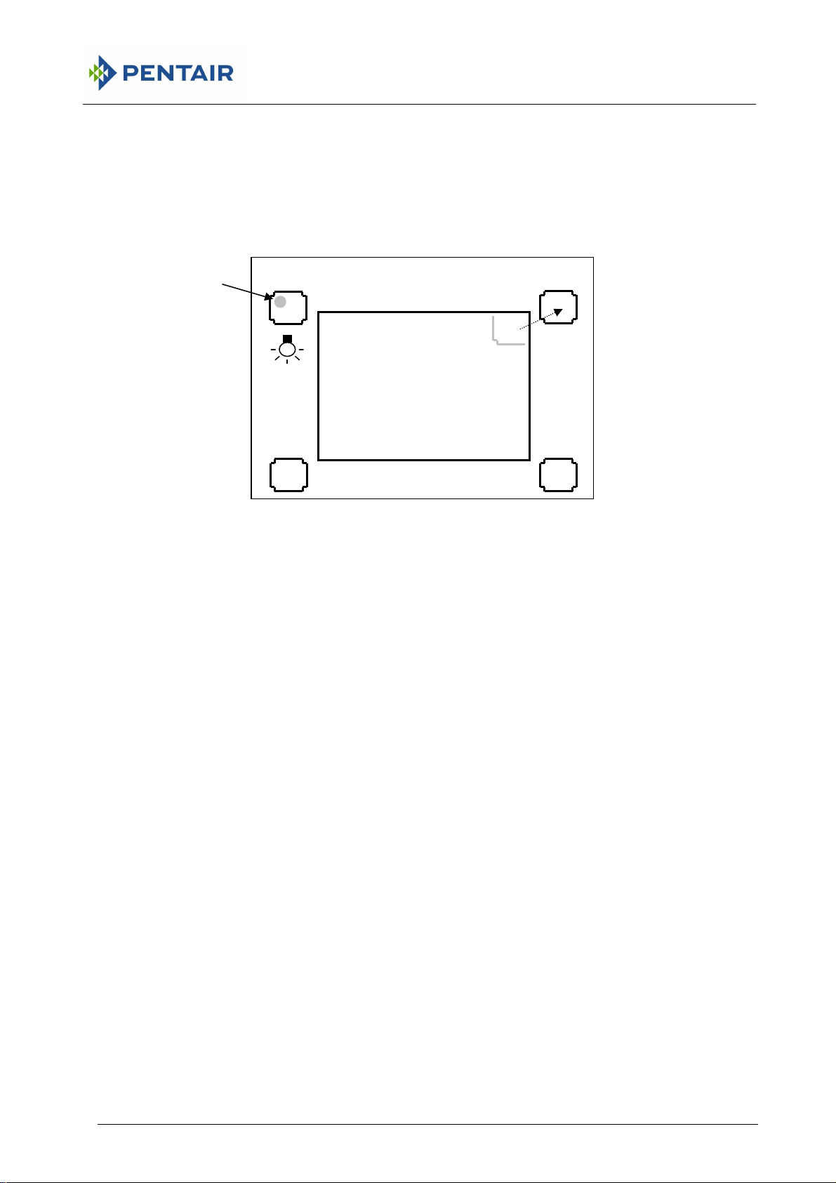
2
I/O
4 OPERATION
4.1 CONTROLS
Flashing
“ON” indicator
There are four control switches arranged around the display screen. Operate the
switches by touching one end of the actuator onto the glass in the marked area.
Keep the actuator in position until you see a change in the display or the flashing
indicator.
The two top switches are used for the main control functions. They take a few
seconds to operate so that there is less chance of any accidental actions.
HAFFMANS RPU 352, RPU 353, RPC 80 RPC 50
Icon relates to
this switch
Display
DISPLAY
4.2 I/O SWITCH
The top left switch is the I/O (on/off) switch. Switch the instrument on by
activating this switch. Switch the instrument off by activating and holding this
switch for at least ten seconds. The display shows you what is happening.
Remove the actuator after the instrument switches off.
If there are any recorded files they will be saved during the time the instrument is
switched off.
You cannot switch the instrument off when the battery is charging from a Redpost
printer/charger unit or a Redpost battery charger.
4.3 INDICATOR
The small green lamp on the panel flashes once per second to show that the
instrument is operating. This lamp also flashes quickly five times to acknowledge
the action of either of the two top switches.
RPU 352, RPU 353, RPC 80, RPC 50 Page 15 of 112
Page 16

HAFFMANS RPU 352, RPU 353, RPC 80 RPC 50
2
4.4 DISPLAY ILLUMINATION
The I/O (on/off) switch also turns on the backlight that lights up the display.
When any switch is operated or there is any other activity, such as connecting a
probe, the backlight will turn on. It will turn off again after a short time to save
battery power. Activate the I/O switch (for about half a second) to turn on the
backlight without causing any other action.
If there is very little charge in the battery then the backlight will not turn on. This
saves unnecessary battery drain.
4.5 SWITCH FUNCTIONS AND ICONS
The I/O (on/off) switch always keeps the same function but for the other three
switches the display will show a small “icon” to indicate the function of each
switch. The icon is in the same corner as the switch it relates to. The switch icon
becomes inverted (black for white) when the switch is operated. If a switch has
no icon then it has no function at that time.
4.6 AUTO POWER ON
The instrument will automatically switch on when it is connected to a Redpost
printer/charger or a Redpost battery charger. This allows the battery charging to
be controlled and the charging information to be displayed.
The I/O (on/off) switch will not turn the instrument off while it is connected to a
charger but it can still be used to turn on the display backlight.
4.7 AUTO POWER OFF
The instrument uses several methods to reduce battery power consumption. The
automatic control of the display backlight is described above.
If the instrument is idle and waiting to record a file it will automatically switch off
after ten minutes. The instrument is idle if no switches are activated, no data
communication is taking place and it is not connected to an active battery
charger.
If the instrument is idle and displaying the results of a recorded file it will
automatically switch off after twenty minutes.
When the instrument switches off automatically any recorded files are saved.
To resume normal operation activate the I/O (on/off) switch or connect the
instrument to a Redpost battery charger.
Page 16 of 112 RPU 352, RPU 353, RPC 80, RPC 50
Page 17

2
4.8 LOW BATTERY CONDITION
If recording is taking place when the battery charge level falls below 15%
then recording will stop and the file will be saved. This ensures that
recordings cannot be corrupted by low battery condition. The results
screen will show the reason for stopping.
If there is less than 15% charge in the battery then the backlight cannot be
switched on. This helps to ensure that the battery lasts for as long as
possible. The backlight increases the battery drain by about four times.
At an even lower level of charge (below 5%) the whole instrument will turn
off. Any recorded files will be saved. If you switch the instrument on again
in this state it will stay on for only a few seconds. Connect the instrument
to a Redpost battery charger as soon as possible.
The instrument continuously monitors its own battery use and battery
charging to gauge the amount of charge that remains in the battery. If the
battery voltage falls to a low level unexpectedly it may indicate that the
battery is not correctly holding its charge. This can happen after several
years of use. If this problem occurs the display will warn you that the
battery may need to be replaced. More information can be found in the
“Maintenance” section.
HAFFMANS RPU 352, RPU 353, RPC 80 RPC 50
RPU 352, RPU 353, RPC 80, RPC 50 Page 17 of 112
Page 18

HAFFMANS RPU 352, RPU 353, RPC 80 RPC 50
2
Page 18 of 112 RPU 352, RPU 353, RPC 80, RPC 50
Page 19

2
5 STARTING
Temperature of
probe (channel 2)
Only for PRU-353:
Pressure
(channel 3)
HAFFMANS RPU 352, RPU 353, RPC 80 RPC 50
Temperature of
probe (channel 1)
Start
recording
Set pressure
zero
5.1 PREPARING THE INSTRUMENT
Switch on the instrument. If there are any problems, such as insufficient charge in the battery,
the display will give the information you need. Before the temperature probes are connected
the location and numbering of the sockets is shown on the display.
Set up the bottle or can in the correct size holder and fit the correct length temperature probe.
Connect this probe into the channel 1 socket. Channel 1 is to the right of the display. When
calculating the results channel 1 is given most importance and is assumed to show the product
temperature.
Select the spray probe or second container temperature probe and connect it to channel 2.
Channel 2 is to the left of the display.
Both sockets must always be occupied. To run without one of the probes you can connect a
dummy temperature probe. (A special plug marked with a ‘T’.) You can also configure a
channel to be permanently inactive: see the section “Key Plug”. An inactive channel is shown
by an X on the screen.
RPU 352, RPU 353, RPC 80, RPC 50 Page 19 of 112
Page 20
HAFFMANS RPU 352, RPU 353, RPC 80 RPC 50
1
3
7
2
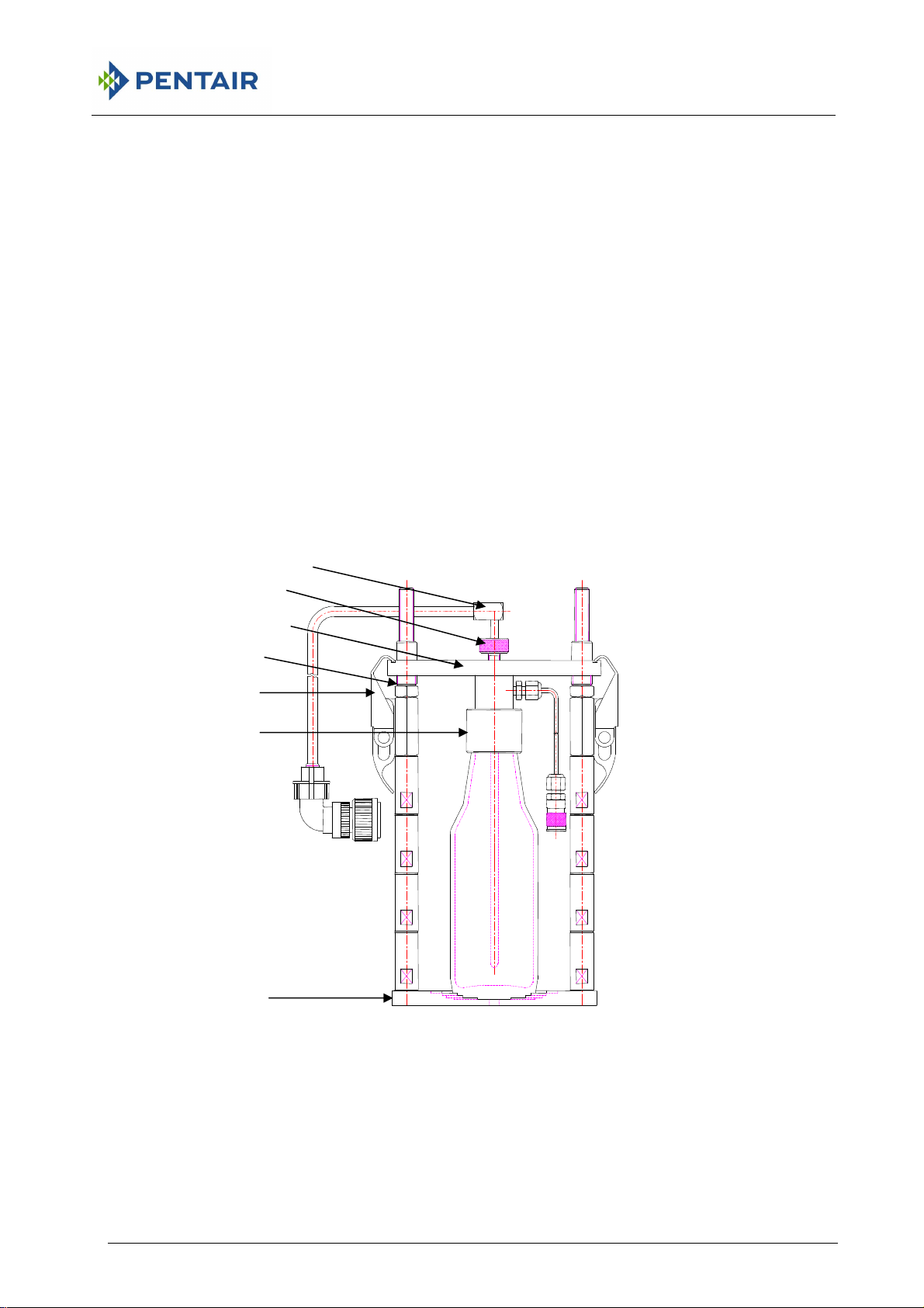
Only for RPU-353:
In order to make a record run the pressure sensor can be connected in the same bottle as the
temperature sensor.
Preparation for measurement in bottles and cans. For bottles an additional centre ring (1) is
needed to centre the bottle. Preparations are:
1. Adjust the Piercing mechanism (2) by placing a sufficient amount of distance tubes
Bottle length = 80 (base ring) + n x 40 (distance ring) + n x 5 (distance ring)
2. Tighten nut (3).
3. Place bottleor can on the base (4)
4. Lower the plate with pressure adapter and temperature sensor (5).
5. Close the piercing mechanism (2)
6. Optional snifting. By pushing the levers (2) up and down quickly, the pressure in the
bottle or can gets down to the atmospheric pressure
7. Push the temperature sensor (6) down into the bottle and adjust the sensor with the
screw (7). This process is described in the section “Appendix 1: Background Information”
6
5
2
4
Page 20 of 112 RPU 352, RPU 353, RPC 80, RPC 50
Page 21

HAFFMANS RPU 352, RPU 353, RPC 80 RPC 50
2
5.2 PRESSURE ZERO SETTING
Only for PRU-353
Before you connect the pressure fitting to the PRU-353 you should set the zero
point of the pressure channel (channel 3). This setting should be made before
each recording run and compensates for changes in atmospheric pressure. With
the pressure port open to the atmosphere activate the bottom right switch (0).
After the zero has been set you can connect the pressure fitting to the port and
then pierce the container to let the pressure reach the sensor. The pressure port
(channel 3) is on the back edge of the instrument to the left of the display.
5.3 THERMOMETER
When the instrument is ready to record, the temperature of the probes is shown
on the display, updated every second.* In this form the instrument can be used
as a highly accurate thermometer.
5.4 STARTING THE RECORDING
When you are ready to put the instrument into the pasteuriser, start recording by
activating the top right switch ().
*
The illustration shows the English language version in °C and bar. The text changes according to the language and
units selected for the display.
RPU 352, RPU 353, RPC 80, RPC 50 Page 21 of 112
Page 22

HAFFMANS RPU 352, RPU 353, RPC 80 RPC 50
2
Page 22 of 112 RPU 352, RPU 353, RPC 80, RPC 50
Page 23

2
6 RECORDING
Only for PRU-353:
The temperature of the probes, the pressure sensor reading and the elapsed
recording time are shown on the display throughout the recording run.*
HAFFMANS RPU 352, RPU 353, RPC 80 RPC 50
Stop
recording
Animated
Elapsed
6.1 STOPPING THE RECORDING
When the instrument exits from the pasteuriser you can stop the recording by
activating the top right switch () or by unplugging either probe. Recording will
also stop after the maximum time (4 hours) or if the charge in the battery
becomes too low.
As soon as recording stops the results are displayed.
You can record again without erasing the previous file. Use the top right switch
to access the main menu and then select “Record Again”. (See “Results”
section.)
6.2 SCREEN TEMPERATURE
The display screen will switch off if the instrument is too hot (above 70°C). This
avoids damage to the screen. Recording will continue normally under these
conditions and the flashing green indicator lamp shows that the instrument is
operating. Normal display operation will resume as soon as the instrument has
cooled.
Warning
The instrument should never be operated at temperatures above
the maximum ambient temperature shown in the specifications
.
.
*
The illustration shows the English language version in °C and bar. The text changes according to the language and
units selected for the display.
RPU 352, RPU 353, RPC 80, RPC 50 Page 23 of 112
Page 24

HAFFMANS RPU 352, RPU 353, RPC 80 RPC 50
2
Page 24 of 112 RPU 352, RPU 353, RPC 80, RPC 50
Page 25
2
7 RESULTS
The calculated results are displayed as soon as recording stops. It is also
possible to select different representations of the results.
7.1 RESULTS DISPLAYS
There are three different results displays and they can be selected from the main
menu. The right hand switch above all the results screens gives access to this
menu. Later in this manual the “Menus” section explains the operation of the
menus in detail.
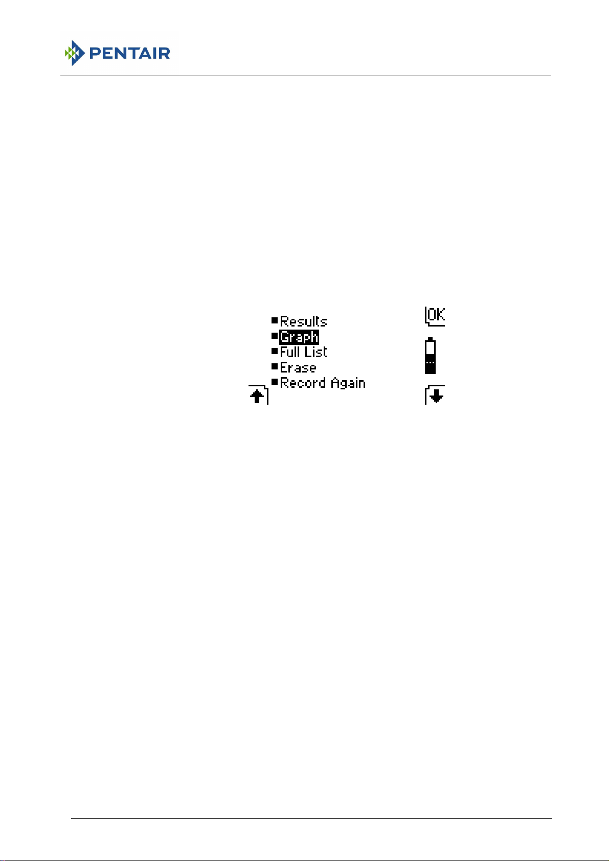
7.2 MAIN MENU
HAFFMANS RPU 352, RPU 353, RPC 80 RPC 50
• The calculated Results such as the total PU achieved.
• The Graph of the file with a movable cursor that allows you to select one
record to be shown in detail.
• The Full list of all the records in the file in detail.
• Erase the recorded file(s). See more details below. You should print out
important files or copy them to a PC before you erase them.
• Record again without erasing the previous file(s). Up to four files can be
saved in the instrument at any one time. When the memory is too full to save
any more files, or when the battery is being charged, this item is not shown.
Files that have been printed using the RPC-80 printer/charger unit must be
erased before you can record any more files.
If more than one file has been recorded you will be asked to choose the file you
wish to show.
7.3 CALCULATED RESULTS
The results are set out on five “pages” with up to 3 items on each page. The right
hand switch below the screen () is used to move to the next page and then
from the final page back to the first ().
On the screen the channel number relating to each result is shown at the left
hand side of each line as a white figure on black. Channel 1 is given most
importance and is assumed to show the product temperature.
RPU 352, RPU 353, RPC 80, RPC 50 Page 25 of 112
Page 26

HAFFMANS RPU 352, RPU 353, RPC 80 RPC 50
2
• The total PU value achieved (channel 1)
• The unique ID number of the file
• The total recording time (and optional date & time †)
• The maximum temperature recorded (channel 1)
• The total time during which the temperature was within 2°C of the maximum
• The temperature at the exit from the pasteuriser (channel 1)
• The total PU value achieved (channel 2)
• The maximum temperature recorded (channel 2)
• The total time during which the temperature was within 2°C of the maximum
• The PU cut-off temperature (applies to both temperature channels)
• The total time accumulating PU’s: i.e. while temperature was at or above the
• The total time accumulating PU’s (channel 2)
• The maximum pressure recorded (channel 3)
• The total time during which the recorded pressure was within 0.2 bar of the
• The reason for stopping recording
All these results are calculated wherever possible. If the file contains any offscale records (outside the recording range of the instrument) then some results
may be invalid. A warning is shown if this is the case and some items may be
shown as “unknown”. Off-scale records can be caused by a faulty temperature
probe.
† If the instrument’s clock has been set then the date and time at the start of
the recording is shown alternating with the total recording time. See section
“Key Plug” for clock setting.
(channel 1) *
(channel 2) *
PU cut-off temperature (channel 1)
maximum (channel 3) *
7.4 ERASING A FILE
When files are no longer required you can remove them by selecting the Erase
option from the main menu. The “Menus” section explains the operation of the
menu in detail.
Move the menu highlight to Erase and hold the actuator on the top right (OK)
switch for ten seconds. The display shows you what is happening. All recorded
files are erased together. After the files have been erased you can release the
switch and the instrument will be ready to record again.
When you use the RPU-352, PRU-353with the RPC-80 printer/charger unit you
can erase the files, after they have been printed, by using the control panel of the
RPC-80. Files that have been printed using the RPC-80 must be erased before
you can record any more files.
*
The limits for this result vary according to the display units selected.
Page 26 of 112 RPU 352, RPU 353, RPC 80, RPC 50
Page 27

2
8 CALCULATED RESULTS
Shows the data in the recorded file reduced to the most important details.
8.1 TOTAL PU ACHIEVED
The total number of Pasteurisation Units accumulated during the recording run.
This is calculated using your chosen definition of PU and cut-off temperature.
You can change the PU calculation by using the key plug. More details of the
calculation are given in the “Key Plug” section and in appendix I Background
information.
Your packaging specification will normally set the PU definition and a target PU
value for each product to ensure sufficient pasteurisation.
8.2 UNIQUE ID NUMBER
This file identity number is a combination of the instrument serial number and a
running number that advances for each recording. It is therefore unique to the
file.
HAFFMANS RPU 352, RPU 353, RPC 80 RPC 50
8.3 TOTAL RECORDING TIME
The total elapsed time from the moment you start recording by activating the
switch until recording stops. Recording may be stopped in a variety of ways either
under your control or automatically. (The reason for stopping is given as the final
result.)
If the instrument’s internal clock has been set then the date and time the
recording started is also shown. These extra items show alternately with the total
recording time.
8.4 MAXIMUM TEMPERATURE
The maximum recorded temperature.
Your packaging specification may call for a certain maximum product
temperature and exceeding it could produce unacceptable flavour changes.
8.5 TIME NEAR MAXIMUM TEMPERATURE
The total time during which the temperature was within 2°C of the maximum.
This gives an approximate value for the time the product was within the
pasteuriser holding zone. The limit for this result changes to 4°F when
temperature is displayed in Fahrenheit.
RPU 352, RPU 353, RPC 80, RPC 50 Page 27 of 112
Page 28

HAFFMANS RPU 352, RPU 353, RPC 80 RPC 50
2
8.6 TEMPERATURE AT PASTEURISER EXIT
The moment that the instrument leaves the pasteuriser is judged by a rise in light
level from the relatively dark interior. Inspection lights inside the pasteuriser may
prevent this result from being calculated. The light sensor can be seen on the
front panel between the two left hand control switches, don’t cover this area with
tape or adhesive labels.
Your packaging specification may call for a maximum product exit temperature. If
the product leaves the pasteuriser at too high a temperature the flavour may be
impaired.
This result is shown for channel 1 only because that channel is assumed to show
the product temperature.
8.7 PU CUT-OFF TEMPERATURE
At or above this temperature PU’s are accumulated. Below this temperature they
are not. The cut-off temperature can be adjusted by using the key plug. More
details of the cut-off and the PU calculation are given in the “Key Plug” section.
Your packaging specification may call for a particular PU cut-off temperature to
ensure that pasteurising conditions are correct.
8.8 TIME ADDING PU’S
The total time during which the product temperature was high enough for PU’s to
be achieved and added to the total. The product temperature was at or above
the cut-off temperature for this length of time.
8.9 MAXIMUM PRESSURE
Only for PRU-353
The maximum recorded gauge pressure.
Attention!
Your container specification will show a maximum acceptable
internal pressure and exceeding it could lead to leakage or container
damage.
8.10 TIME NEAR MAXIMUM PRESSURE
The total time during which the gauge pressure was within 0.2 bar of the
maximum. The limit for this result changes to 4 psi or 0.2 kg/cm2 when pressure
is displayed in alternative units.
Only for PRU-353
8.11 REASON FOR STOPPING
You can stop recording by activating the switch or by unplugging either probe.
Recording will also stop after the maximum time (4 hours) or if the charge in the
battery becomes too low.
Page 28 of 112 RPU 352, RPU 353, RPC 80, RPC 50
Page 29
2
menu screen
cursor
Channel 1
Channel 2
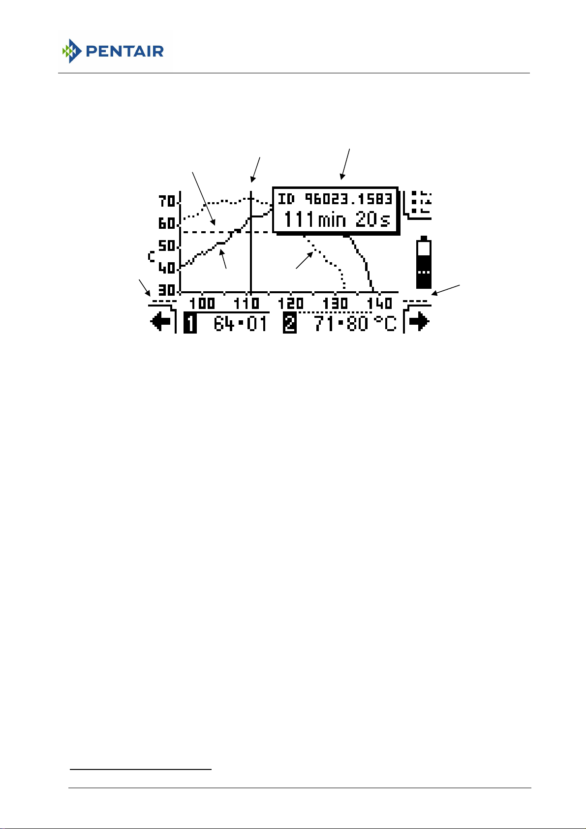
9 GRAPH
HAFFMANS RPU 352, RPU 353, RPC 80 RPC 50
Indicates that
graph extends
PU cut-off temperature
to left
Move cursor
to left
Shows the data in the recorded file as a graph. The temperature (in the selected
display units) runs up the vertical axis and elapsed time (in minutes) runs along
the horizontal. *
This panel appears
Flashing
Full details of record under cursor
when cursor moves
Return to
Indicates that graph
extends to right
Move
cursor to
right
9.1 CURSOR MOVEMENT
The record under the cursor is shown in detail below the graph. The two switches
below the screen are used to move the cursor. Moving the cursor to the right
moves it towards the end of the file.
The cursor moves by one record as soon as you operate the switch. If you hold
the switch for a short time then the cursor starts to move continuously, slowly at
first and then faster, for as long as the switch is held. When the cursor reaches
the last record in the file the switch outline becomes dim and it no longer has any
effect.
Moving the cursor to the left (towards the start of the file) works in a similar way.
Whenever the cursor is moving, the elapsed time of the record under the cursor
is shown in a panel at the top right of the screen. The ID number of the file is
also shown here.
*
The illustration shows the graph in °C. The details change according to the units selected for the display.
RPU 352, RPU 353, RPC 80, RPC 50 Page 29 of 112
Page 30

2
9.2 GRAPH LINES
Channel 1 shows as a solid line on the graph while channel 2 shows as a dotted
line. The position of the PU cut-off temperature is shown as a dashed line. The
horizontal lines above each channel in the detailed record show the style of the
line for that channel.
ONLY FOR PRU-353
The pressure channel (channel 3) is not shown as a line on the graph but if the
pressure channel is active then the gauge pressure is shown in the detailed
record area alternating with the temperature records.
An inactive channel is not shown on the graph and is shown with an X in the
detailed record.
The vertical temperature scale adjusts automatically so that the maximum
reading of the highest channel is always on the graph. A record that is below the
scale leaves a gap in the graph.
If the whole graph is wider than will fit on a single screen then the cursor causes
the graph to scroll from side to side so that the required portion is visible. Small
dashed lines at the left or right of the time axis indicate that the graph extends
further in that direction.
HAFFMANS RPU 352, RPU 353, RPC 80 RPC 50
:
9.3 OFF-SCALE RECORDS
Off-scale records are too high or too low to fit within the available recording range
of the instrument. The available recording range is shown in the “Specification”
section. Off-scale records can be caused by a faulty probe.
Any record that is too high or too low for the recording range does not show on
the graph and leaves a gap in the graph. In the detailed record area, records
above the top of the recording range show as a row of ‘+’ signs. Similarly a row
of ‘-’ signs indicates a record that is too low for the recording range.
Display backlight
You can use the top left switch at any time to turn on the display backlight.
Page 30 of 112 RPU 352, RPU 353, RPC 80, RPC 50
Page 31

2
Channel details
10 FULL LIST
HAFFMANS RPU 352, RPU 353, RPC 80 RPC 50
Elapsed time from
start of file
Move line
to left
“Time line”
shows position in file
Shows a list of all the data in the recorded file. *
10.1 TIME LINE MOVEMENT
Four records from a file can be shown in detail on the screen. The “time line”
shows the position of these records in relation to the whole file. The two switches
below the screen are used to move the time line. Moving the line to the right
shows records nearer to the end of the file.
The line moves by one record as soon as you operate the switch. If you hold the
switch for a short time then the line starts to move continuously, slowly at first and
then faster, for as long as the switch is held. When the line reaches the last
record in the file the switch outline becomes dim and it no longer has any effect.
Moving the line to the left (towards the start of the file) works in a similar way.
The time line is not shown for very short files (under 1 minute).
An inactive channel gives a blank column with an X in the header.
Display backlight
You can use the top left switch at any time to turn on the display backlight.
File ID number
ONLY FOR
PRU-353
Return to
Move line
to right
*
The illustration shows the list in °C and bar. The details change according to the display units selected.
RPU 352, RPU 353, RPC 80, RPC 50 Page 31 of 112
Page 32

HAFFMANS RPU 352, RPU 353, RPC 80 RPC 50
2
Page 32 of 112 RPU 352, RPU 353, RPC 80, RPC 50
Page 33

2
condition
11 BATTERY CHARGING
The battery in the instrument can be re-charged by the Redpost RPC-80
printer/charger or the Redpost RPC-50 battery charger. You can connect the
charger to either socket. If you connect to the charger before recording a file you
see the complete charging information on the screen.*
HAFFMANS RPU 352, RPU 353, RPC 80 RPC 50
Warning
Do not leave the battery on charge continuously for more than 24
hours.
Battery
condition*
11.1 BATTERY INFORMATION
All the other display screens show the battery condition using just the small
battery image from the complete diagram. This shows when the battery is being
charged by an arrow head that moves up the battery image. The speed of
movement shows the charge rate. The dotted line shows the minimum level of
charge needed to start recording.
Moves faster for
higher charge rate
Instrument type and serial number
Software
Level of black filling
shows battery
Charge
rate*
version
Indicates that charger
Charge above here
before recording
11.2 BATTERY TEMPERATURE
The charge rate is controlled by several factors including battery temperature.
The battery will not charge if it is too hot and in that case the arrow head in the
battery diagram will be stationary. Charging will resume as soon as the battery
has cooled.
*
The illustration shows the English language version. The text changes according to the language selected for the
display.
RPU 352, RPU 353, RPC 80, RPC 50 Page 33 of 112
Page 34

HAFFMANS RPU 352, RPU 353, RPC 80 RPC 50
2
Page 34 of 112 RPU 352, RPU 353, RPC 80, RPC 50
Page 35

2
item
down
12 MENUS
HAFFMANS RPU 352, RPU 353, RPC 80 RPC 50
Move highlight
up
There are stages in the operation and configuration of the instrument when you
need to choose an action etc. from a menu list. A menu shows all the possible
choices or items in a vertical list. The method of operation is the same in every
case although there can be as few as 2 and as many as 6 items in the menu list.
12.1 MOVING THE HIGHLIGHT
The two switches below the screen are used to move the highlight over the item
in the list that you wish to select.
The highlight moves down by one item as soon as you operate the right hand
switch. If you hold the switch for a short time then the highlight starts to move
down continuously for as long as the switch is held. When the highlight reaches
the bottom item the switch outline becomes dim and it no longer has any effect.
Moving the highlight up with the left switch works in a similar way.
Highlighted
item
Select highlighted
Move highlight
12.2 SELECTING AN ITEM
Operate the top right (OK) switch to select the item you have highlighted.
Example
RPU 352, RPU 353, RPC 80, RPC 50 Page 35 of 112
Select French
language
Page 36

HAFFMANS RPU 352, RPU 353, RPC 80 RPC 50
2
Page 36 of 112 RPU 352, RPU 353, RPC 80, RPC 50
Page 37

HAFFMANS RPU 352, RPU 353, RPC 80 RPC 50
2
13 KEY PLUG (CONFIGURATION)
The key plug is a special plug marked with a ‘K’ which can be inserted into either
probe socket and puts the instrument into configuration mode. This allows you to
change the way the instrument operates. The key plug restricts access to this
mode so that changes are not made unintentionally. You can use the key plug
only when there are no recorded files in the instrument and it is not connected to
an active battery charger.
The parameters you can change are presented on a series of screens. Each
screen shows the symbol of a key at the bottom. The screen first shows you the
present setting or value, if that is correct you can activate the top right (OK)
switch to move to the next screen.
Activate the lower control switches if you need to change the present value.
Sometimes you choose from a menu, sometimes change the value directly.
When the value is correct you should always activate the top right (OK) switch.
Changes you make on a screen are only saved when you activate the OK switch
for that screen.
13.1 OUTPUT TO OTHER EQUIPMENT
The settings you make with the key plug will decide how the results are shown on
the display of the RPU-352 OR PRU-353.
When used with other equipment the final output device dictates all settings.
Therefore when you use the RPU-352, PRU-353with the RPC-80 printer/charger
the settings you make on the RPC-80 and the clock in the RPC-80 will take
priority when results are calculated for printing. Similarly when connecting to a
PC the settings and clock in the PC take priority when results are displayed or
printed by the PC.
13.2 LANGUAGE
You can select the language used for the text on the display. The decimal point
symbol used for numerical output is also changed according to the language you
select. English will use the point, other languages the comma.
13.3 DISPLAY CONTRAST
You can adjust the appearance of the display to give the best contrast. This is
set during manufacture and will seldom need changing. Adjust so that the
background “off” dots become just visible compared to the clear glass at the
edges of the screen. Adjusting for the darkest “on” dots will not give the best
contrast.
The changes you can make are intentionally kept quite small. You can however
set the maximum + or – value, save it with the OK switch and then repeat the
adjustment for greater changes. See “Leaving configuration” below.
RPU 352, RPU 353, RPC 80, RPC 50 Page 37 of 112
Page 38

2
13.4 CLOCK
You can set the current date and time. Setting the clock in this way is optional. If
recorded files are printed and then erased using the RPC-80 printer/charger then
the clock settings of the RPC-80 will be automatically copied into the RPC-353. If
set, the clock will be used when results are shown on the display.
The screen first shows the present setting for the date. If you wish to make any
changes then activate the lower right (+/-) switch otherwise move on by activating
the OK switch.
You change the year, month and day by using the lower switches. A flashing
indicator appears under the item you are changing. When the first item is correct
use the top right () switch to move to the next item and so on.
If you make a mistake you cannot move the cursor backwards but you can start
the date entry process again as described in the next paragraph.
When you have moved past the last item the screen changes and you have the
chance to make more changes by activating the (+/-) switch again. If the date is
now correct you must save the changes you have made by activating the OK
switch.
The screen then changes to show the present setting for the time on a 24 hour
clock system. If you wish to make any changes then activate the lower right (+/-)
switch otherwise move on by activating the OK switch.
You change the hours and minutes by using the lower switches in the way
described above for the date. The seconds cannot be changed and will always be
set to zero. You must end by saving the changes you have made by activating
the OK switch.
HAFFMANS RPU 352, RPU 353, RPC 80 RPC 50
13.5 DISPLAY UNITS
You can choose to display all temperatures in either Celsius (°C) or Fahrenheit
(°F).
Whenever you change the temperature display units the PU calculation is also
changed to the default values for those units (See below).
ONLY FOR PRU-353:
You can choose to display gauge pressures in bar, psi or kg/cm2.
Page 38 of 112 RPU 352, RPU 353, RPC 80, RPC 50
Page 39

2
13.6 ACTIVE CHANNELS
You can make the channels active or inactive using this screen. Inactive
channels do not use up any storage memory and so longer recordings can be
made if required.
If you make a channel inactive in this way it will remain inactive for all recordings
until you change the setting again using the key plug. To make a temperature
channel temporarily inactive you can also use a dummy plug. (A special plug
marked with a ‘T’.) All temperature probe sockets must be occupied before you
start a recording run, even for inactive channels.
If you wish to change the active state of one of the channels then activate the
lower right (+/-) switch otherwise move on by activating the OK switch. On this
screen a tick () represents an active channel and a cross (X) an inactive one.
A flashing indicator appears under the channel you are changing. When the first
channel is correct use the top right () switch to move to the next. You can
leave a channel as it is by moving straight to the next one.
When you have moved past the third channel position the screen changes and
you have the chance to make more changes by activating the (+/-) switch again.
If the channel states are now correct you must save the changes you have made
by activating the OK switch.
HAFFMANS RPU 352, RPU 353, RPC 80 RPC 50
13.7 PU CUT-OFF TEMPERATURE
You can change the cut-off temperature in steps of 0.1°C.
13.8 PU CALCULATION – BASE
You can select a Base value of 60, 70 or 80°C.
13.9 PU CALCULATION – Z
You can select a Z value of 6.94*, 7 or 10°C.
If you set a PU definition other than the standard for beer (i.e. other than Base =
60°C and Z = 7°C) the results display will show the calculation you have chosen.
*Note that 6.94°C is equivalent to a value of 12.5°F: often used in American textbooks.
13.10 PU CALCULATION – FAHRENHEIT
If you have selected to display in °F then the default PU definition will be Base =
140°F and Z = 12.5°F. The cut-off can be changed i n steps of 0.1°F. You can
select a Base value of 140, 160 or 180°F and a Z value of 12.5 or 18°F.
RPU 352, RPU 353, RPC 80, RPC 50 Page 39 of 112
Page 40

2
13.11 RECORDING INTERVAL
This screen allows you to select the time interval between recordings. You can
choose any value between 2 and 60 seconds. The factory setting is 10 seconds.
13.12 EQUIPMENT NUMBER
This screen allows you to set your own equipment number or identification for the
instrument. This can consist of up to 15 letters or numbers and will be printed
with the results by the Redpost RPC-80 printer/charger. This identification may
be required for ISO9000 schemes. Only upper case Roman script letters without
accents can be used with numerals, space, period (.) and forward slash (/).
The screen first shows the present equipment number or a series of blank spaces
if nothing has been set yet. If you wish to change or add to the equipment
number then activate the lower right (+/-) switch otherwise move on by activating
the OK switch.
You change the first character position of the equipment number using the lower
switches. A flashing indicator appears under the character you are changing.
When the first character is correct use the top right () switch to move to the next
character position and so on. You can leave a character blank by moving straight
to the next position.
If you make a mistake you cannot move the cursor backwards but you can start
the whole entry process again (see below). After entering all the characters you
want you can move quickly through any remaining blank spaces by holding the
top right () switch for a few seconds.
When you have moved past the last character position the screen changes and
you have the chance to make more changes by activating the (+/-) switch again.
If the equipment number is now correct you must save the changes you have
made by activating the OK switch.
HAFFMANS RPU 352, RPU 353, RPC 80 RPC 50
13.13 MAINS FREQUENCY
Choose 50 or 60 Hz according to the nominal frequency of your local mains
supply. This setting helps the instrument to reject interference.
After you activate the OK switch for this screen you have finished the
configuration cycle.
13.14 LEAVING CONFIGURATION
Remove the key plug if you have made all the changes you need. You can
continue through another configuration cycle if you need to make more changes.
You can remove the key plug at any time or switch the instrument off using the
I/O (on/off) switch but remember that any changes you make on a screen are
only saved when you activate the OK switch for that screen.
The configuration cycle will be interrupted if you connect the instrument to a
battery charger.
Page 40 of 112 RPU 352, RPU 353, RPC 80, RPC 50
Page 41

2
14 OUTPUT
The RPU-352, PRU-353instrument can be used as a stand-alone PU & pressure
monitor or it can be connected to a variety of other equipment so that the
recorded files can be permanently saved and/or printed.
14.1 STAND ALONE OPERATION
With its detailed display of calculated results, graph and full list of all records it is
possible to obtain all the information about a file directly from the display of the
instrument. The only other equipment required is a Redpost RPC-50 battery
charger.
14.2 CONNECTION TO RPC-80
The instrument connects to the Redpost RPC-80 printer/charger. Printed results
are available and a status report for the instrument can be obtained. Connection
to a PC is possible using the serial port on the RPC-80.
The settings you make on the RPC-80 will take priority over the settings in the
RPU-352, PRU-353 when results are calculated for printing. File start time will be
calculated using the clock in the RPC-80 as a reference.
When files are erased using the control button on the RPC-80 the clock settings
are automatically copied into the RPU-352, PRU-353. This applies to RPC-80
software version ‘p’ or later.
HAFFMANS RPU 352, RPU 353, RPC 80 RPC 50
14.3 CONNECTION TO PC
It is possible to connect the instrument to a PC using the Redpost RPC-50
battery charger. The same connection is also possible using the serial port on
the RPC-80 (See manuals for RPC-50 or RPC-80).
Recorded files can also be copied and carried to a remote PC using an optional
hand-held infrared data transfer unit (Future product.)
The settings you make on the PC will take priority over the settings in the RPU352, PRU-353 when results are calculated for display or printing. File start time
will be calculated using the clock in the PC as a reference. The software
currently offered for the PC does not alter the clock settings in the RPU-352,
PRU-353.
RPU 352, RPU 353, RPC 80, RPC 50 Page 41 of 112
Page 42

HAFFMANS RPU 352, RPU 353, RPC 80 RPC 50
2
Page 42 of 112 RPU 352, RPU 353, RPC 80, RPC 50
Page 43

HAFFMANS RPU 352, RPU 353, RPC 80 RPC 50
2
15
MAINTENANCE
General
To maintain the accuracy and reliability of the equipment we recommend that it is
serviced and re-calibrated (with the probes) at regular intervals. Under light
conditions of use this should be carried out at least every 1500 recording runs.
When the equipment is heavily used, particularly where high pasteuriser
temperatures are involved as with fruit juices, then the service and re-calibration
should take place every year.
If this work is done by the manufacturers or an approved agent then the
calibration and service details can be recorded in the equipment and are
available via the status report.
The regular service will replace both temperature probe sockets and the battery
(see below) and so ensure reliable operation.
Dessicant
The dessicant in the electronics housing needs to be replaced annually.
Probe sockets
The probe sockets should be lubricated after every 50 recording runs using the
contact treatment grease supplied. This protects the sockets from corrosion and
greatly extends their service life. A lubrication reminder is shown on the display
at the correct times.
If you leave a probe or dummy plug permanently connected to one of the
channels it is important to unplug it occasionally and lubricate the socket before
replacing it. The lubrication reminder applies to all sockets.
If the equipment has not been returned for servicing as recommended above
then after about a year of heavy use (or two years of light use) then the exchange
unit should be replaced as a precaution. The exchange unit includes both
temperature probe sockets and the battery. Full fitting instructions are enclosed
with the new part.
Probes
The probes do not require routine maintenance. Handle them with care. When
re-calibrating the equipment always re-calibrate all the probes at the same time.
Only for PRU-353:
Pressure port
The pressure port should be occasionally cleaned. Remove the instrument from
its frame and stand it in a tray of hot water about 25 mm deep. The water should
just cover the pressure port. Never insert anything into the port or attempt to
remove the pressure connector.
RPU 352, RPU 353, RPC 80, RPC 50 Page 43 of 112
Page 44

2
Battery
60ºC Test Plug
HAFFMANS RPU 352, RPU 353, RPC 80 RPC 50
Always switch the instrument off when it is not in use. If the instrument is left idle
it will switch off automatically.
Do not leave the battery on charge continuously for more than 24 hours.
If the equipment has not been returned for servicing as recommended above
then as the battery ages it will not hold as much charge as it did when new. The
instrument can detect this and when the problem becomes severe it may give a
warning on the display that the battery should be replaced. After about a year of
heavy use (or two years of light use) the exchange unit should be replaced as a
precaution. The exchange unit includes both temperature probe sockets and the
battery. Full fitting instructions are enclosed with the new part.
If you unplug the exchange unit and then reconnect it the instrument will assume
you have fitted a new battery. Never unplug the exchange unit unless you
intend to replace it with a new one.
If you plan to store the instrument unused for more than 6 months you should first
fully re-charge the battery. When the instrument is left unused, even though it is
switched off, the battery gradually loses charge by a process known as “self
discharge”. If possible give the battery a few hours charge every 3 months
during storage.
The supplied 60ºC Test Plug can be used as a diagnostics tool for the RPU
monitor. It can be connected to the main unit to verify the unit’s measuring
functionality. To use the 60ºC Test Plug, connect it to one of the unit’s channels.
When the unit measures a temperature between 59,8ºC and 60,2ºC with the Test
Plug connected, the unit functions correctly. When different temperatures are
measured with the Test Plug connected, the unit needs to be serviced.
Page 44 of 112 RPU 352, RPU 353, RPC 80, RPC 50
Page 45

HAFFMANS RPU 352, RPU 353, RPC 80 RPC 50
2
16 FREQUENTLY ASKED QUESTIONS
Battery
1) Sometimes the battery charge indicator doesn’t move even though the instrument is
connected to the charger. What’s wrong?
2) When I switch the instrument on it often has less charge in it than when I switched it off.
Why?
3) How long should I leave the instrument connected to the charger?
4) How long will the battery last?
5) How is battery charging controlled?
6) The display tells me that a new battery has been installed. I haven’t fitted a new battery,
what’s going on?
7) The charge rate shown on the RPC-80 is not the same as that shown on the PU monitor.
Which is correct?
Controls
8) Which switches control the display backlight?
ONLY FOR PRU-353:
9) Why can’t I zero the pressure channel? The message tells me that “error is too great”.
Results
10) If the product temperature is exactly equal to the cut-off temperature will any PU’s be
achieved?
11) The PU value displayed by the RPU-352, PRU-353is not the same as that printed for the
same run by the RPC-80. Why?
ONLY FOR PRU-353:
12) The maximum pressure value displayed by the PRU-353 is lower than that printed for
the same run by the RPC-80. Why?
13) Why is the file start time shown on the display of the RPU-352, PRU-353almost an hour
different from the start time in the results printed by my PC?
14) Why is the exit temperature sometimes not included in the results?
15) Why doesn’t the date and time of my file appear on the display of the PU monitor? It
appears correctly on the printed results from my PC.
16.1 BATTERY AND BATTERY CHARGING
1) Sometimes the battery charge indicator doesn’t move even though the instrument is
connected to the charger. What’s wrong?
Nothing’s wrong. When the battery is too hot to charge more quickly the charge rate is lowered
to the “trickle” charge rate which has to be set to a low level so that charging conditions are
safe. If the instrument is very hot then no charging is possible. When the instrument has cooled
down the charge rate will increase and refill the battery. The heat may have come from outside,
for example from the pasteuriser or from inside from the process of charging the battery itself.
When the battery is full it will also stop charging although the instrument will occasionally
increase the charge rate to “trickle” to make up for any gradual losses. The battery is quickly
refilled and charging stops again. This cycle repeats as long as the instrument is connected to
the charger. Do not leave the battery on charge continuously for more than 24 hours.
If there are no recorded files then the main battery display will show all the charging information
including the reason why the battery is not charging.
RPU 352, RPU 353, RPC 80, RPC 50 Page 45 of 112
Page 46

HAFFMANS RPU 352, RPU 353, RPC 80 RPC 50
2
2) When I switch the instrument on it often has less charge in it than when I switched it off.
Why?
When the instrument is switched off and left unused the battery gradually loses charge by a
process known as “self discharge”. When it is next switched on the instrument estimates how
much charge has been lost in this way and compensates by reducing the charge percentage.
3) How long should I leave the instrument connected to the charger?
There is no need to leave the instrument on the charger after the battery shows 100% which is
full charge. You should not leave the charger connected for more than 24 hours.
4) How long will the battery last?
The specification shows examples of the instrument running time that can be expected from a
fully charged battery.
The service life of a battery will depend on the conditions of use. Giving an exact life time is
difficult. Heavy use at high pasteurising temperatures such as used for fruit juices will reduce
the life. Under such conditions a battery might be expected to last for about a year. With light
use and at beer pasteurising temperatures the battery might last for 2 years.
5) How is battery charging controlled?
The instrument continuously monitors its own battery use and any battery charging to gauge the
amount of charge that remains in the battery. This allows the percentage charge to be
displayed either as a number or as the black fill level on the battery information diagram.
Whenever the charger is connected the charge rate is controlled by the instrument taking into
account the state of charge and temperature of the battery and the total charging time.
Charging can be fastest when the battery is empty and cool but must be slower when the
battery is nearly full or is hot. The aim is to replace the charge as quickly as possible without
overcharging or overheating the battery. This ensures a long service life for the battery.
6) The display tells me that a new battery has been installed. I haven’t fitted a new battery,
what’s going on?
If you unplug the exchange unit (which includes the battery) and then reconnect it the
instrument will assume you have fitted a new battery. NEVER UNPLUG THE EXCHANGE
UNIT unless you intend to replace it with a new one. See the “Maintenance” section of the
operating manual.
If the battery voltage falls to a low level and then recovers it may appear as though the battery
was removed and replaced by a new battery. This can happen if the battery is failing to hold its
charge after a year or two of use. It might also happen if the instrument has been switched off
and left unused for a long period (six months or more).
A new battery must be charged to a certain level before use and so the instrument must be
connected to the charger for several hours. The instrument display gives information about this
commissioning process.
Page 46 of 112 RPU 352, RPU 353, RPC 80, RPC 50
Page 47

HAFFMANS RPU 352, RPU 353, RPC 80 RPC 50
2
In your case the instrument has wrongly sensed a battery change. You should follow the
instructions on the display and charge the battery as if it were new. The internal clock settings
and any saved files will have been lost. If the same problem occurs again within a short time
then the battery is beginning to fail and you should fit a new exchange unit.
7) The charge rate shown on the RPC-80 is not the same as that shown on the PU monitor.
Which is correct?
The RPC-80 is compatible with the RPU-352, PRU-353PU & pressure monitor but it was
designed for use with equipment that has a different battery type. The definitions of the charge
rates are not exactly equivalent but charging will take place correctly. Refer to the display on
the PU monitor for the correct charging information.
16.2 CONTROLS
8) Which switches control the display backlight?
The display backlight is switched on by any of the following actions: activating any switch (even
those that have no other function at the time), plugging or unplugging anything into either socket
or starting any communications activity that causes a message to be displayed. The backlight
will switch off again after one minute unless another action keeps it on.
If you only wish to switch on the backlight you should use the I/O (on/off) switch because then
there is no chance of the switch causing any other unwanted operation (unless you hold it for
more than 10 seconds!).
ONLY FOR PRU-353:
9) Why can’t I zero the pressure channel? The message tells me that “error is too great”.
You should set the zero for the pressure channel before each recording run to compensate for
changes in atmospheric pressure. Therefore, the pressure port must be open to the
atmosphere and so you should set the zero before you connect up to the pressure fitting on the
container. The pressure must be within ±0.5 bar of standard atmospheric pressure otherwise
the zero correction cannot be made.
If the port is open to the atmosphere and you still get the message “Can’t set zero - the error is
too great” then the pressure port may be blocked. This is most likely to be a problem when
pasteurising soft drinks with high sugar content. Clean the port as directed in the “Maintenance”
section of the operating manual. If the problem persists then there may be a fault in the
pressure sensor.
RPU 352, RPU 353, RPC 80, RPC 50 Page 47 of 112
Page 48

HAFFMANS RPU 352, RPU 353, RPC 80 RPC 50
2
16.3 RESULTS
10) If the product temperature is exactly equal to the cut-off temperature will any PU’s be
achieved?
Yes, PU’s will be achieved and added to the total. The precise definition of the PU cut-off (see
“Results” section of the operating manual) is as follows: “At or above this temperature PU’s are
accumulated. Below this temperature they are not.”
This definition also applies to the timing result displayed as “Adding PU’s” but often printed as
“Time above cut-off”. The definition of the result has always been the same but in printed
results the headings used in the past were not always so precise.
11) The PU value displayed by the RPU-352, PRU-353 is not the same as that printed for the
same run by the RPC-80. Why?
Remember that the final output device dictates all settings for PU calculation, date and time.
The RPC-80 recalculates the results from the raw data based on values you choose when
setting up the RPC-80. The clock in the RPC-80 is also used as a reference for the file timing.
These features make it easy to maintain a plant-wide standard for PU calculations and the date
& time and to change those standards without making modifications to all the monitors. When
using the RPU-352, PRU-353 with the RPC-80 you must be aware that different standards for
PU calculation (including PU cut-off temperature) may apply to the displayed and printed
results.
The same applies when connecting the PU monitor to a PC. The settings you make in the
program running on the PC will take priority over the settings in the RPU-352, PRU-353 when
results are calculated for display or printing. File start time will be calculated using the clock in
the PC as a reference.
ONLY FOR PRU-353:
12) The maximum pressure value displayed by the PRU-353 is lower than that printed for the
same run by the RPC-80. Why?
The final output device dictates all settings for PU calculation, date, time, etc. and this also
extends to the pressure results. The previous answer gives more details.
The RPC-80 can be set to make a correction for errors introduced by the older pressure fittings
where the head space in the can is very small. These errors are very small for the more recent
pressure fittings and so these corrections are not made in the PRU-353. We recommend that
the head space correction in the RPC-80 is turned off. See the RPC-80 configuration manual.
13) Why is the file start time shown on the display of the RPU-352, PRU-353 almost an hour
different from the start time in the results printed by my PC?
The final output device dictates all settings for PU calculation, date and time. The previous
answers give more details. In this case the clock in the PC was probably adjusted automatically
for Summer Time (Daylight Saving) but you have not changed the clock in the RPC-353.
If the PU monitor is used with the RPC-80 printer/charger then the clock will be automatically
Page 48 of 112 RPU 352, RPU 353, RPC 80, RPC 50
Page 49

HAFFMANS RPU 352, RPU 353, RPC 80 RPC 50
2
updated every time files are printed out and then erased. (The software in the RPC-80 must be
version ‘p’ or later.) This makes it easy to maintain a plant-wide standard for date & time
without making modifications to all the monitors. The software used in the PC does not
currently offer this facility.
14) Why is the exit temperature sometimes not included in the results?
The moment that the instrument leaves the pasteuriser is judged by a rise in ambient light level
from the relatively dark interior. If there are inspection lights inside the pasteuriser or if for any
other reason the light level is too high inside the pasteuriser or too low outside it (where the
instrument exits) then the result may not be calculated. It may be necessary to improve the
lighting at the exit end of the pasteuriser particularly during night shifts.
The sensing sequence is triggered by the channel 1 temperature first rising above the PU cutoff temperature and then falling below it again before the exit from the pasteuriser. If this does
not happen then the result is not calculated. (Channel 1 is assumed to read the temperature of
the product.)
The light sensor can be seen on the left of the instrument’s front panel between the two left
hand control switches, don’t cover this area with tape or adhesive labels.
15) Why doesn’t the date and time of my file appear on the display of the PU monitor? It
appears correctly on the printed results from my PC.
The date and time when the file recording started is shown on the first page of results only if the
instrument’s internal clock has been set. These extra items are shown alternately with the total
recording time. When the PC is used to print the results the clock in the PC is used as a
reference for the file timing.
If you wish to see the file start date and time on the display then you must set up the internal
clock.* See “Key Plug” section of the operating manual. As supplied the instrument’s clock is
not usually set. When a new exchange unit is fitted (which includes the battery) the internal
clock settings are lost.
* If the PU monitor is used with the RPC-80 printer/charger then the clock will be automatically
set or updated every time files are printed out and then erased. (The software in the RPC-80
must be version ‘p’ or later.) This makes it easy to maintain a plant-wide standard for date &
time without making modifications to all the monitors. The software used in the PC does not
currently offer this facility.
RPU 352, RPU 353, RPC 80, RPC 50 Page 49 of 112
Page 50

HAFFMANS RPU 352, RPU 353, RPC 80 RPC 50
2
Page 50 of 112 RPU 352, RPU 353, RPC 80, RPC 50
Page 51

HAFFMANS RPU 352, RPU 353, RPC 80 RPC 50
2
INSTRUCTION MANUAL
RPC-80
PRINTER/CHARGER
Essential reading!
Page 52

HAFFMANS RPU 352, RPU 353, RPC 80 RPC 50
2
Page 53

HAFFMANS RPU 352, RPU 353, RPC 80 RPC 50
2
17 TECHNICAL SPECIFICATIONS
Voltage : 82-275V, 50/60Hz
Dimensions (LxWxH) 310x240x150 mm
Weight 4,5 kg
Charging time 6 hours for full charge (300 serie)
Display LCD, back illuminated, 2 lines, 24 characters
Outputs USB for printing
RS-232
RPU 352, RPU 353, RPC 80, RPC 50 Page 53 of 112
Page 54

HAFFMANS RPU 352, RPU 353, RPC 80 RPC 50
2
Page 54 of 112 RPU 352, RPU 353, RPC 80, RPC 50
Page 55

HAFFMANS RPU 352, RPU 353, RPC 80 RPC 50
2
18 INTRODUCTION
The RPC-80 converts the data from the RPU.-351, RPU-352 and RPU-353 into an easy to
understand tabulated result that is printed on a separate printer by just pressing one button.
Furthermore the data can be passed on to a computer. The instrument has a menu driven
operation programme which enables adaptation of the instrument to any pasteurisation process.
Adjustable are among others:
• P.U.-calculation formula (base-value and Z-value).
• Lower cut-off temperature.
• Graph format.
• Units of temperature and pressure.
• Language.
• Calibration check timing (for ISO 9000 certification).
• Furthermore 8 templates can be stored so that a recording run can be simply qualified.
A limited number of adjustments apply to the combination with the RPU.-120 monitor.
RPU 352, RPU 353, RPC 80, RPC 50 Page 55 of 112
Page 56

HAFFMANS RPU 352, RPU 353, RPC 80 RPC 50
2
Page 56 of 112 RPU 352, RPU 353, RPC 80, RPC 50
Page 57

HAFFMANS RPU 352, RPU 353, RPC 80 RPC 50
2
19 UNPACKING
Before despatch the PRU-352 / RPU-353 was checked and tested by Haffmans BV. Make sure
that the content of the delivery is complete and undamaged.
If the delivery is incomplete or damaged, please contact Haffmans BV or the representative/agent
designated by Haffmans BV, immediately (appendix IV). Always include the serial number, order
number or invoice number (given by Haffmans BV) of the PRU-352 / RPU-353 in the
correspondence.
The delivery contains:
• Play back unit type RPC-80.
• Connecting cable.
• USB printer cable.
• Mains cable (depending on the destination; Euro, CH, I, GB, USA, Aus).
• Cd-rom Redlink-II.
• Instruction manual PRU-352 / RPU-353, RPC 80, RPC-50.
• Instruction Manual Redlink-II.
RPU 352, RPU 353, RPC 80, RPC 50 Page 57 of 112
Page 58

HAFFMANS RPU 352, RPU 353, RPC 80 RPC 50
2
•
Page 58 of 112 RPU 352, RPU 353, RPC 80, RPC 50
Page 59

2
20 CONTROL PANEL
HAFFMANS RPU 352, RPU 353, RPC 80 RPC 50
Warning
Haffmans
-REDPOST RPC-80
Fig. 20.1 Control panel
Before using the RPC-80 first carefully read this chapter
2 Line display
3 Switches
RPU 352, RPU 353, RPC 80, RPC 50 Page 59 of 112
Page 60

HAFFMANS RPU 352, RPU 353, RPC 80 RPC 50
2
Page 60 of 112 RPU 352, RPU 353, RPC 80, RPC 50
Page 61

2
Link to
21 USE
HAFFMANS RPU 352, RPU 353, RPC 80 RPC 50
Warning
Read this chapter carefully before using the RPC-80. The RPC-80 is not
waterproof.
21.1 SWITCHING ON
Switch on the mains switch of the RPC-80. The display will light up and briefly show time and
date. The Canon printer must be switched on, don't try to start printing until the "on line" lamp is
lit steadily. Always check that there is enough paper in the Canon printer before starting to use
the RPC-80.
21.2 CONNECTING THE MONITOR
The RPC-80 will now be showing
Connect a monitor that has some files recorded in it, use the same lead to connect to the new
2OO series and the older 100 series monitors. For connections see fig 5.1.
ATTENTION
!
If the P.U. monitor has two sockets, use socket number 1.
"TRYING TO COMMUNICATE WITH MONITOR..."
monitor
Mains Power In
On /OFF
Data to printer
DC power to
printer
Haffmans-REDPOST RPC-80
Fig 21.1 RPC-80 connections
RPU 352, RPU 353, RPC 80, RPC 50 Page 61 of 112
Page 62

2
21.3 PRINTING RECORDED FILES
HAFFMANS RPU 352, RPU 353, RPC 80 RPC 50
ATTENTION
When a monitor has been connected the display changes to
serial number and the word
show its function. Press this button. The display changes to
recorded files are printed out. All the pages of the printed graphs, results and listed data for one
recording run are identified by the same unique file number (200 series monitors) or print run
number (100 series monitors).
!
Do not switch the P.U. Monitor off until all printing has been completed.
Leave the P.U. monitor connected to the printer charger until the
required charging time is over.
PRINT
"FOUND...",
appears on the bottom line over the left hand button to
"PRINTING..."
and the monitor
and all the
21.4 AFTER PRINTING
After the printing is finished the print run can be started again.
21.4.1 200 SERIES P.U. MONITORS.
After all the files have been printed the display changes to
erase the files ,the 200 series monitors will only switch off when they have no files stored. Leave
the monitor on charge for at least 15 minutes. During that time the battery charge rate will show
on the display and after about 15 minutes the monitor will switch itself off automatically. When
the idle lamp on the monitor has stopped flashing you can disconnect the monitor and record
more files.
"ERASE ALL FILES"
Press OK to
ATTENTION!
21.4.2 100 SERIES P.U. MONITORS.
After all the files have been printed the battery charge rate will be shown on the RPC-80
display. Wait until the trickle charge level before you disconnecting the monitor. Don't
disconnect the monitor while the battery is still fast charging.
Don’t disconnect the monitor while the battery is still fast charging.
Page 62 of 112 RPU 352, RPU 353, RPC 80, RPC 50
Page 63

HAFFMANS RPU 352, RPU 353, RPC 80 RPC 50
2
22 CONFIGURATION SETTINGS
When you first switch on the RPC-80 an introductory display of time and date is shown for about
5 seconds. If you hold any of the control buttons in until this display finishes you will enter the
setting section. Using the configuration section you can tailor the operation of the RPC-80
playback unit to suit your exact requirements.
When you have made your chosen settings you return to the normal operating mode and the
normal simplicity of control. The RPC-80 is supplied in a " default" configuration with many of
the features described in this manual turned off It is perfectly possible to continue to use the
playback unit in that form but the extra features, once set up correctly, can extend the
usefulness of the whole monitoring system.
22.1 CLOCK SETTING
After entering the configuration press OK to set the clock. And select
HOUR
The clock in the RPC-80 is the "master clock" for the time of day marked on each recording of
the 200 series monitors. This keeps all the monitors in one installation running perfectly in step
with one another.
or
RESET DATE AND TIME
•
FINE ADJUST
button to freeze the clock and start it running at an exact time signal. Corrections can
also be made by stepping forwards or backwards.
•
+/- ONE HOUR
•
RESET DATE & TIME
very seldom be required if small time corrections are made every month. The day of the
week is not set but is calculated when required.
is for corrections to the clock time of up to a minute. Hold the + or -
for changing time zones and for summer time (daylight saving).
, for starting from scratch with a new time and date. This will
by pressing the ←
MORE
FINE ADJUST, +/- ONE
or
MORE
→ buttons.
22.2 REPORT PRINTING
This allows you to print short status reports for the RPC-80 or for any 200 series monitor that is
connected. The report for the RPC-80 shows the settings chosen for the graph ranges etc.
22.3 TEMPLATE SETTING
If enabled, this allows you to choose the correct template for comparison with the current
recorded run before starting to print. You can also print the directory of all available templates.
RPU 352, RPU 353, RPC 80, RPC 50 Page 63 of 112
Page 64

HAFFMANS RPU 352, RPU 353, RPC 80 RPC 50
2
Page 64 of 112 RPU 352, RPU 353, RPC 80, RPC 50
Page 65

HAFFMANS RPU 352, RPU 353, RPC 80 RPC 50
2
23 CONFIGURATION MENU SECTION
The configuration section is protected by a simple password system that is designed to prevent
inadvertent operation. To enter the configuration section, first enter the setting section in the
normal way by switching on and holding down any button until the operating display of time and
date is over. Choose
number to the password number in just the same way that you would set the year. The
password number is
set the correct password number, you will move into the configuration section.
23.1 GENERAL FORMAT SET-UP
This section covers the general format of the printed text, graphs and display.
23.1.1 SELECT LANGUAGE
Changes the language that will be used for all the text and displays. The languages are English,
French, German and Spanish. When the 100 Series P.U. monitors are used with the RPC-80
they produce text and displays in the language set here by the
23.1.2 SELECT DECIMAL POINT
Offers a choice of two number display formats using the dot (99.9) or the comma (99,9) to
separate the integer part from the fractional part of the number.
23.1.3 SET GRAPH FORMATS
Leads you into the settings for all the graph variables and introduces the idea of user formats.
23.1.4 P.U.-USER
Format for P.U. user sets up the graph format for use with P.U. monitors. When the 100 Series
P.U. monitors are used with the RPC-80 they produce all output in the units set here by the
UNITS menu. Choose the starting point of the temperature and pressure graph scales. Choose
the size the graph major division steps for the temperature and pressure graph scales. Choose
from the following units:
• For temperature channels; °C or °F.
• For pressure channels; bar, lb./in² or kg/cm².
Graph style
For maximum clarity and ease of interpreting the graph choose the starting point and step sizes
from the numbers O, l, 2, 5, 10, 20, 50 etc. The total span of each scale will depend on the step
size and the number of major divisions that fit onto a page. This depends on the graph style and
the paper size.
Choose the graph style, inch or metric sizes with major graph divisions of one inch or 20
millimetres. The standard grid with major divisions and tenths accurately divides each grid
square into tenths and makes the graph easier to interpret. Turning the grid off completely will result in slightly faster graph printing in most cases.
SET CLOCK
1991
. The clock and calendar will not be disturbed by this but, if you have
and then
RESET DATE AND TIME
. Change the year
SELECT LANGUAGE
menu.
RPU 352, RPU 353, RPC 80, RPC 50 Page 65 of 112
Page 66

HAFFMANS RPU 352, RPU 353, RPC 80 RPC 50
2
Head space correction
The RPU-353 use a pressure sensor inside the instrument that connects to the container via a
quick release coupling and a fine flexible tube. This causes a slight increase in volume. If the
theoretical volume of the head space of the container is known and entered into the RPC-80
then the unit can make a first order correction for the error. The pressure sensor connections
must be cleaned out after each run so that the pipe and coupling are empty if this error
correction is to operate correctly. The error is only significant when head space volume is less
than about 20 millilitres. The maximum correction allowed will increase the recorded pressure
by 5%.
HEAD SPACE CORRECTION?
HEAD SPACE VOLUME enter the theoretical volume in millilitres (same as cubic centimetres).
Channel names
SET CHANNEL NAMES
The names can have up to 15 characters (letters or numbers). Channels 1 and 2 are
temperature channels, channel 3 is the pressure channel. For instance channel 1 "PRODUCT"
an d channel 2 "SPRAY". These names appear on the printed results.
Make the correction Yes or No.
sets up names for the three possible channels of the P.U. monitor.
ATTENTION
!
After you have set up the graph format for the P.U. monitor user you will
be returned to the SET GRAPH FORMATS display where you can exit
this part of the setting section by pressing the CANCEL button. If you
continue by pressing the OK button you can move on to set up the
formats for the other user.
23.2 P.U. CALCULATION SET-UP
This section covers the selection of P.U. calculation constants and of the P.U. Cut-off
temperature. By choosing
the 100 and 200 series. For the base- and Z value see general product information.
CUSTOM CALCULATION
the P.U. calculation can be changed for
ATTENTION!
P.U. cut-off and the graph
The P.U. Cut-off temperature is printed on the graph as a dashed line so that it is easy to see
the area where the temperature trace exceeds the Cut-off and where P.U.s are being added to
the total.
In the case of two different Cut-off levels being set, they cannot both be shown on the graph
when the RPC-80 is used with a multi-channel monitor.
The P.U. value calculated by the 100 series can be different form the
P.U. value calculated by the RPC-80.when a custom calculation is used.
Page 66 of 112 RPU 352, RPU 353, RPC 80, RPC 50
Page 67

HAFFMANS RPU 352, RPU 353, RPC 80 RPC 50
2
Dual channel monitors
It is possible to set up different P.U. Cut-off temperatures for channel 1 and channel 2 on dual
channel monitors. With
P.U. ON CHANNEL 2
it is possible to turn off the P.U. calculation on
channel 2. with buttons marked YES and No for your reply.
23.3 TEMPLATE SET-UP
A template is a stored record of an ideal pasteurising run made when everything is operating
correctly. Subsequent recorded runs are compared with the template and the degree of fit is
calculated. A recorded run can also be printed as a graph superimposed on a template. Many
templates can be stored and can be given a name or other identification. When templates are
being used there will be extra items on the results page to show you which template is selected
and how well it compares to the current run. The channel 1 trace on the graph is printed with a
grey shaded area around it that shows the deviation (if any!) between the trace of the template
and the current run. Any other active channels are also compared with the template but the
deviation is not shown on the graph to avoid too many confusing traces.
1. TEMPLATES NOT REQUIRED turns off the templates altogether.
2. OPEN TEMPLATE ACCESS
In order to select a template first some templates must be recorded. When choosing
OPEN TEMPLATE ACCESS
TEMPLATE RECORDING?
from the template menu you will be asked the question
with YES and No buttons for your reply.
Template recording takes place when the monitor is in normal use not during
configuration. Open template access allows the operator to select templates in the
settings section. The basic settings menu will show an extra item for setting templates.
This also allows the operator to print out a template directory, which is a list of all
available templates with their names and dates of recording. The template selection
menu in the settings section shows all the recorded templates with their names.
Stepping through this menu the operator can then choose the template to use for
comparison with the recorded files in the monitor. Once the operator has chosen a
template it will remain in force for each subsequent print run until changed. It is not
necessary to re-select the template at the start of each print run.
3. FIXED TEMPLATE allows you to select the template in the configuration section. The
template, once chosen, can only be changed by returning to the configuration section. In
this case there are no extra settings or choices that need to be made by the operator
during day to day running.
RPU 352, RPU 353, RPC 80, RPC 50 Page 67 of 112
Page 68

HAFFMANS RPU 352, RPU 353, RPC 80 RPC 50
2
23.3.1 TEMPLATE RECORDING
When template recording is switched on the operator will be given the choice to record each run
as a template after it has been printed out. Each template takes a number and when you record
a new template the template number that is first offered is the lowest free template number. You
can choose a different number if you wish. If you choose the number of an existing template you
will be asked if you really wish to erase the existing template and record the new one in its
place. Template numbers run from 1 to99. When the templates are recorded they can also be
given a name and this name can be set up at the time of recording. You will be able to change
the name later (See "Editing a template name"). It is possible to leave the name blank by
pressing the OK button when the blank name is first printed. Deleting templates is only possible
by saving new templates using the same template number. The date of recording is
automatically added to the template record.
While the template is being recorded SAVING TEMPLATE.... will show on the display. Never
switch off the RPC-80 until the TEMPLATE SAVED OK message is shown. Saving a template
can take up to 20 or 30 seconds.
Template channel one
It is important when using templates to allocate channel 1 to the product temperature. Channel
1 in a template, controls the way that the template trace and the recorded run are synchronised.
The template and the P.U. monitor recordings are synchronised as the temperature traces pass
through the P.U. cut-off temperature. If either temperatures (template or recorded) are above
the P.U. cut-off at the start of the graph or if either remains below the P.U. cut-off for the whole
of the graph then the template comparison will be impossible.
Template recording requirements
In order to save a recorded pasteurisation run as a template the following conditions must all be
met:
1. Channel 1 must have been active in the P.U. monitor.
2. The run must contain no off-scale readings on any active channel.
3. The run must contain at least 25 records.
Meaning a run must be more than 4.2 minutes long with a recording interval of 10 seconds or
more than 12 minutes long with a recording interval of 30 seconds, pro-rata for other
intervals.
4. There must have been no communications errors during the data transfer from the P.U.
monitor to the RPC-80.
5. All the expected data must have been received from the P.U. monitor.
Templates and the pressure channel
If a recording run that includes a pressure channel is saved as a template then any head space
volume correction in force at the time will be used and the corrected pressure will be saved.
This means that when you subsequently use the template, a valid head space correction must
be in force if the template comparison is to be meaningful on the pressure channel.
Page 68 of 112 RPU 352, RPU 353, RPC 80, RPC 50
Page 69

HAFFMANS RPU 352, RPU 353, RPC 80 RPC 50
2
Degree of fit to template
The degree of fit to the selected template is printed in the results. The comparison starts when
both traces pass through the P.U. Cut-off temperature for the first time and stops when the
shortest trace ends, see table 7.1.
Table 7.1
Description Arbitrary % Average temperature deviation Average pressure deviation
very good 80 - 100
good 60 - 80
fair 40 - 60
poor 20 - 40
very poor 00 - 20
±0 to ±1°C ±0 to ±0.2 bar
±1 to ±2°C ±0.2 to ±0.4 bar
±2 to ±3°C ±0.4 to ±0.6 bar
±3 to ±4°C ±0.6 to ±0.8 bar
±4 to ±5°C ±0.8 bar or more
23.4 TEMPLATE EXCHANGE
IMPORT TEMPLATES
to exchange templates between two RPC-80 playback units so once recorded templates can be
used for several pasteuriser lines or at several different sites. The External Link (serial)
connectors of the two RPC-80 units are linked by a short cable and a null modem.
1. Connect the two units with a suitable cable,
2. Select
The display shows
3. Select IMPORT TEMPLATES on the unit that you wish to receive a copy of the
template(s). This unit now becomes the importer and has control over the rest of the
exchange,
4. The importer unit receives a copy of the exporter's template directory,
5. Choose the template you wish to bring over from the other unit,
6. Choose the template number for the new template,
7. The date of recording is added to the imported template record; not the date of
exchange.
EXPORT TEMPLATES
and
EXPORT TEMPLATES
on the unit that already has the recorded template(s).
TEMPLATE EXPORT...
in the template set-up menu allow you
with a
CANCEL
button,
ATTENTION
8. Go to Finished SET-UP. EXIT to return to normal operation.
9. Remove the connecting cable and press
RPU 352, RPU 353, RPC 80, RPC 50 Page 69 of 112
!
While the template is being imported SAVING Template.... will show on
the display. Never switch off the RPC-80 until the TEMPLATE SAVED
OK message is shown.
CANCEL
on the exporter unit.
Page 70

HAFFMANS RPU 352, RPU 353, RPC 80 RPC 50
2
23.5 EDITING A TEMPLATE NAME
Edit Template ID in the template set-up menu allows you to change a template name at any
time after it has been recorded or imported. Select the template name you wish to change and
then edit the name in the normal way. Template names can have up to 15 characters (numbers
or letters) and must be unique.
23.6 MONITOR SET-UP
Active channel set-up
The SELECT ACTIVE CHANNEL display alternates with the serial number of the monitor that
you have connected. Press the OK button to start. The display shows all possible input
channels of the monitor with a tick (√) next to the active ones and a cross (x) next to the inactive
ones. Change the status of the channels (not) needed on the monitor if all is set press the OK
button.
Monitor ID set-up
Each 200 series monitor can be given its own. At first the
with the serial number of the monitor. Press the OK button to start. Set up the ID as required
with a maximum of 15 characters (letters or numbers). The ID can also be left blank if you do
not require it. The active channels you select and the instrument ID that you choose are printed
on the Status Report for the monitor.
SET MONITOR ID
display alternates
23.7 RPC-80 SET-UP
Display contrast
SET DISPLAY CONTRAST to adjust the RPC-80 display to give the desired contrast between
the dots that form the characters and the background. Use the LESS and MORE buttons as
required. The buttons do not repeat if held down.
Cal-check setting
The Cal-check or calibration check feature of the 200 series P.U. monitors performs a simple
test that checks the monitor Input circuit and Input socket. This applies to the temperature
channels only. Test components are built into the lead that connects the monitor to the playback
unit The playback unit keeps track of these checks for each monitor. You can select the
frequency of the checks in this part of the configuration section. The Cal-check takes place with
fixed inputs that represent 60°C and the actual readings are shown as well as the pass or fail
result. Channels are checked even if they have been set inactive. For monitors with several
temperature channels a fixed 60°C test plug is required for all but the fist channel. The pass and
fail criteria are based on the original specification of the monitor. If the monitor fails the Calcheck it can still be used if you wish; it is not banned from operation in any way.
The SELECT CAL-CHECK TIMING menu gives you the choice of daily, weekly or monthly
checks.
You can also choose to never check. The date of the last successful Cal-check is printed on the
Status Report for the monitor. The Cal-check does not apply to the 10O Series P.U. monitors
Page 70 of 112 RPU 352, RPU 353, RPC 80, RPC 50
Page 71

HAFFMANS RPU 352, RPU 353, RPC 80 RPC 50
2
RPC-80 ID set-up
Each RPC-80 can be given its own identification. Press OK to start when the display introduces
SET RPC-80 ID. Set up the ID as required. The ID can have up to 15 characters (letters or
numbers). The ID can also be left blank if you do not require it.
23.8 FULL LIST SET-UP
As well as the normal graph and results it is possible to obtain a printed list of all the recorded
data from a P.U. monitor. This will be printed after the main results page. In this part of the
configuration section it is possible to choose the circumstances under which the full list will be
printed. The list can be printed automatically or the operator can be left to decide if it is required.
The list shows the data for all active channels in tabulated format using the selected units. The
time elapsed since the start of the file is shown in "hours : minutes : seconds" format. If the list
would take up more than 4 pages the operator is offered the chance to abandon printing before
it starts.
NEVER PRINT FULL LIST
The list is never printed and the operator is never asked if the list is required. Playback units are
despatched with this setting.
ALWAYS PRINT FULL LIST
The list is always printed without any intervention by the operator.
ALWAYS ASK
At the end of every print out the operator is asked if the full list is required. The display shows
the simple question PRINT FULL list Now? with YES and No buttons for the reply.
PRINT AFTER PROBLEMS
The list is always printed, without any intervention by the operator, after a run in which a
problem is encountered. A "problem" in this case is an off scale reading on any active channel
or, if templates are in use, a poor or very poor fit to the selected template.
ASK AFTER PROBLEMS
At the end of a print out in which a problem has been encountered the operator is asked if the
full list is required. The display shows the simple question PRINT FULL list Now? with YES and
No buttons for the reply. A "problem" in this case is an off scale reading on any active channel
or, if templates are in use, a poor or very poor fit to the selected template.
23.9 PRINTER SET-UP
PRINTER TYPE
De SELECT Printer TYPE menu offers a choice of printers by name. The RPC-80 is
despatched set for a cannon BJ-10 SX or BJ-200.
PAPER SIZE
De SELECT PAPER size menu offers a choice of UK, USA and European paper sizes by name
and dimensions. The RPC-80 is despatched set for A4 paper size.
RPU 352, RPU 353, RPC 80, RPC 50 Page 71 of 112
Page 72

HAFFMANS RPU 352, RPU 353, RPC 80 RPC 50
2
23.10 EXTERNAL LINK SET-UP
The External Link menu allows you to set the serial format for communications on the link.
These must be set up to match the serial format of the external computer connected to the
external link.
Baud Rate ( 300 to 19200 )
Number of Data Bits ( 7 or 8 )
Number of Stop Bits ( 1 or 2 )
Parity ( None, Odd or Even )
Handshake ( Hard or Soft )
The External Link socket is a female 25 way "D" connector arranged in the RS-232 Data
Terminal Equipment (DTE) format, see table 8.2.
Table 7.2
Pin Signal Name In/Out Notes
1 Chassis ground
2 Transmit Data (TXD) Out
3 Receive Data (RXD) In
4 Request to Send (RTS) Out hard handshake
5 Clear to Send (CTS) In hard handshake
7 Signal ground
14 (test signal) Out fixed "Off" (-9 volts)
20 Terminal Ready (DTR) Out fixed "On" (+9 volts)
Hard Handshake
In the Hard Handshake system the handshaking is managed by two extra signal connections.
The signals are described below from the point of view of the RPC-80. During Hard Handshake
the characters used for Soft Handshake control should not be used. If they are received by the
RPC-80 they will be treated as normal data characters which may produce errors.
1. Clear to Send (CTS) is an input to the RPC-80 that controls the transmitter in the RPC-
80. The signal comes from the RTS or DTR Output of the external computer. When CTS
is On the RPC-80 will transmit its data, when CTS is Off the RPC-80 will wait and not
transmit.
2. Request to Send (RTS) is an Output from the RPC-80 that must control the
transmitter in the external Computer. The signal usually goes to the CTS input of the
external computer. When RTS is On the RPC-80 is ready and able to receive data and
the external computer can transmit, when RTS is Off the external computer must wait
and not transmit.
Page 72 of 112 RPU 352, RPU 353, RPC 80, RPC 50
Page 73

HAFFMANS RPU 352, RPU 353, RPC 80 RPC 50
2
Soft Handshake
In the Soft Handshake system the handshaking is managed without extra signal connections by
sending handshake characters mixed in with the data characters. These handshake characters
are known as "XOn" and "XOff". During Soft Handshake the signals used for Hard Handshake
should not be used. On the RPC-80 the RTS output is always on and the CTS input is ignored.
No connection need be made to either signal.
The XOn character is fixed as ASCII DC1/Hex 11/Decimal 17
The XOff character is fixed as ASCII DC3/Hex 13/Decimal 19
Serial input buffer
The serial data received by the RPC-80 first enters a buffer. In both handshaking systems the
"Not Ready" signal or character is sent by the RPC-80 when the buffer becomes 75% full. When
the RPC-80 buffer is only 50% full then the "Ready" signal. The size of the buffer is fixed at a
total of 255 data characters.
23.11 FINISHED SET-UP : EXIT
Choose this option when you have finished using the configuration section. The RPC-80
playback unit will return to normal operation. All the settings you have made will apply to the
next print out that you make and will be remain in force until you change them. All settings are
remembered when mains power is removed from the RPC-80.
RPU 352, RPU 353, RPC 80, RPC 50 Page 73 of 112
Page 74

HAFFMANS RPU 352, RPU 353, RPC 80 RPC 50
2
Page 74 of 112 RPU 352, RPU 353, RPC 80, RPC 50
Page 75

HAFFMANS RPU 352, RPU 353, RPC 80 RPC 50
2
24 PRINTED RESULTS
The RPC-80 printer/charger unit can print out the results of the P.U. monitors together with a
graphical representation of the recorded data. Several sample sections of printed results are
shown below.
24.1 RESULTS
The results are printed as a graph with a short list of the obtained results, see chapter 2.6 for
explanation of the recorded data. Additionally a full list of off records can be printed. This option
must first be activated in the menu section configuration, see chapter 8.5
24.2 STATUS REPORT
This allows you to print short status reports for the RPC-80 or for any 200 series monitor that is
connected, see paragraph 8.4 for printing. The report for the RPC-80 shows the settings chosen
for:
• Graph ranges etc.
• Channel names.
• P.U. calculation.
• General information of the RPC-80.
The report for the monitor shows:
• Serial number.
• Channel ranges.
• All other settings.
RPU 352, RPU 353, RPC 80, RPC 50 Page 75 of 112
Page 76

HAFFMANS RPU 352, RPU 353, RPC 80 RPC 50
2
Page 76 of 112 RPU 352, RPU 353, RPC 80, RPC 50
Page 77

2
25 SYSTEM ERRORS
HAFFMANS RPU 352, RPU 353, RPC 80 RPC 50
Warning
Only qualified persons should attempt to repair electronics, When
equipment is under guarantee it must in all cases be returned for
repair or replacement if faults occur.
25.1 SYSTEM ERROR 02 & 04.
Input overflow from External link. The link is ignoring the handshake control and is sending data
when the input buffer is full or sending data at the wrong rate.
25.2 SYSTEM ERROR 08 & 09.
Unexpected data from monitor Possibly you switched on the monitor while it was connected to
the playback unit or tried to start a recording run with the monitor still connected.
RPU 352, RPU 353, RPC 80, RPC 50 Page 77 of 112
Page 78

HAFFMANS RPU 352, RPU 353, RPC 80 RPC 50
2
Page 78 of 112 RPU 352, RPU 353, RPC 80, RPC 50
Page 79

HAFFMANS RPU 352, RPU 353, RPC 80 RPC 50
2
26 FAULTY OPERATION
Sometimes an error will occur that prevents the RPC-80 playback unit from completing an
operation. When this happens the display will show a message followed by
PAGE...
with the code number of the error.
26.1 B-MESSAGES
All messages starting with a “B” are messages concerning the battery of the PRC-80
B1
The memory back-up battery in the RPC-80 has failed. The voltage output has fallen too low to
guarantee memory and clock operation. The battery should last approximately seven years but
we recommend that you replace it every five years. The date when the battery is fitted is saved
in the RPC-80 and a warning starts to be issued every week after the battery is five years old.
SEE MANUAL
ATTENTION
B2
The memory back-up battery in the RPC-80 is over five years old. The voltage output may soon
fall too low to guarantee memory and clock operation. Full fitting instructions are included with
the replacement battery. The battery should last approximately seven years but we recommend
that you replace it every five years. The date that the battery is fitted is saved in the RPC-80
and this warning starts to be issued every week after the battery is five years old.
ATTENTION
After you have changed the battery you must enter the correct battery fitting date. This will
ensure that any future battery old age warnings are given at the correct time. The battery fitting
instructions cover this in more detail.
!
Change the battery as soon as possible to prevent loss of clock,
calendar functions and templates
!
Change the battery as soon as possible to prevent loss of clock,
calendar functions and templates
26.2 C-MESSAGES
All messages starting with a “C” are messages concerning the communication of the PRC-80
with other equipment.
C1
There has been an error in the communications between the monitor and the RPC-80. The lead
that connects the monitor to the RPC-80 may have become disconnected.
RPU 352, RPU 353, RPC 80, RPC 50 Page 79 of 112
Page 80

HAFFMANS RPU 352, RPU 353, RPC 80 RPC 50
2
ATTENTION!
Never unplug this lead until the "Printing Finished" message shows and
the charge rate has reduced to trickle charge.
It is possible that an error could be caused by very severe interference from other nearby
equipment or on the mains wiring. If this is suspected then the cause should be investigated
because the levels of interference will have to be very high to cause errors.
Template Exchange
You will also see this message if there is a communications error while transferring the template
directory between two RPC-80 units when exchanging templates.
• Set up the two RPC-80 units in the correct order, see chapter 8.5.3.
• The lead that connects the two units may have become disconnected. Never unplug the
lead until the template exchange is completed.
• Check that you are using the correct type of null modern and cable.
It is impossible to recover from this type of error and you will have to re-start the exchange from
scratch.
C2
it is impossible to communicate with the monitor to set up the active channels etc. This applies
when you are in the "Configuration" mode of operation.
• The lead that connects the monitor to the RPC-80 may have become disconnected.
• The monitor may not be switched on.
• The monitor may be an 100 series type, only the 200 series monitors can be set up this
way.
• You will also see this message if there is a communications error during certain stages
of the Cal-check
ATTENTION
!
It is possible that an error could be caused by very severe interference
from other nearby equipment or on the mains wiring. If this is suspected
then the cause should be investigated because the levels of interference
will have to be very high to cause errors.
Page 80 of 112 RPU 352, RPU 353, RPC 80, RPC 50
Page 81

HAFFMANS RPU 352, RPU 353, RPC 80 RPC 50
2
C3
There has been an error in the communications between the RCP-80 and an external computer
on the External link.
• The lead that connects the external computer to the RPC-80 may have become
disconnected. Never unplug while the
• The data might be send in the wrong format or at the wrong data rate. Check if the
settings of the External link match those of the external computer.
• It is impossible to recover from this type of error and continue the current data transfer.
The external computer will need to re-start the transfer.
"Data Transfer..."
message shows.
ATTENTION!
It is possible that an error could be caused by very severe interference
from other nearby equipment or on the mains wiring. If this is suspected
then the cause should be investigated because the levels of interference
will have to be very high to cause errors.
26.3 M-MESSAGES
All messages starting with a “M” are messages concerning the memory of the PRC-80.
M1
The memory in the clock / calendar chip has become corrupted and the settings stored in it
have been lost. The memory has been tested and found to be operating correctly. The most
likely reason for the memory loss is that the back-up battery power was lost for a short time.
This may have been due to a fault in the battery or the connector. You should check that the
battery connector has not been disconnected by accident.
• The settings will have all been returned to 00:00:00 entries
• Templates will have been turned off.
• The clock time will have returned to 1st January 1992.
M2
The memory that stores all the operational settings for the RPC-80 has become corrupted and
the settings in it have been lost. The memory has been tested and found to be operating
correctly. The following items will have been lost;
• The optional channel names will have been replaced by blank entries
• The clock time will have returned to 00:00:00 on 1st January 1992
• All saved templates will have been deleted and templates turned off
The memory used has a minimum data retention time of over 10 years. If the fault occurs it may
be necessary to replace this memory, return the instrument for repair.
RPU 352, RPU 353, RPC 80, RPC 50 Page 81 of 112
Page 82

HAFFMANS RPU 352, RPU 353, RPC 80 RPC 50
2
ATTENTION!
M3
The memory that stores the recorded templates for the RPC-80 has become corrupted and all
the data in it has been lost. The memory has been tested and found to be operating correctly.
The most likely reason for the memory loss is that the back-up battery power was lost for a short
time. This may have been due to a fault in the battery or the connector. Check that the battery
connector has not been disconnected by accident.
M4
The memory that stores the recorded templates for the RPC-80 has become corrupted and the
data in it has been lost. The memory has been tested and found to be faulty, and has been
taken out of service.
If this fault occurs it will be necessary to replace the template memory. Return the instrument for
repair. The RPC-80 will continue to function normally without the template facility.
Enter the correct time and date that the back-up battery was fitted
followed by the serial number of the instrument. Until these items have
been correctly entered the fault will recur on each power up.
The saved templates will have all been deleted and templates turned off.
The templates will have been turned off and templates cannot be used.
26.4 P-MESSAGES
All messages starting with a “P” are messages concerning the printing.
P1
The printer is not responding to the instructions. See the trouble-shooting section of your printer
manual.
• Check that the printer is "on line"
• Do not try to start printing before the "on line" lamp is lit permanently.
• Check for sufficient paper
• Check for a paper jam.
• Check the data lead connecting the RPC-80 and the printer.
100 Series monitors
If you start to print as soon as the "PRINT" button appears, the data from the monitor is still
being received and the on/off lamp on the monitor is on steadily. If the paper runs out or any
other printer fault causes a hold up of more than about 6 minutes then the monitor will return to
idle with the on/off lamp flashing every 2 seconds. The print run may then be incomplete. Once
the printer fault is cleared you should abandon the run by disconnecting the monitor from the
RPC-80 then reconnect it and restart the print run.
Page 82 of 112 RPU 352, RPU 353, RPC 80, RPC 50
Page 83

HAFFMANS RPU 352, RPU 353, RPC 80 RPC 50
2
26.5 T-MESSAGES
All messages starting with a “T” are messages concerning the templates.
T1
The recording of the template selected for use has been damaged in some way and it cannot be
used.
• The template has been deleted.
• If the mains fails or you switch off the RPC-80 during the time that the template is being
saved you will most likely generate a corrupted template.
ATTENTION!
Never switch off the playback unit until the
TEMPLATE SAVED OK
message is shown.
T2
There are no templates recorded yet. In order to select a template you must first record some.
You may need to go into the "Configuration" mode to enable template recording, see chapter
8.5.3. The message T2 and
TEMPLATE EXCHANGE
is shown when trying to use the
Template Exchange to export templates before you have recorded any.
T3
Templates use disabled because channel 1 of the P.U. monitors is not active.
Channel 1 is assumed to carry the main record of the product temperature as it is pasteurised.
The template and the P.U. monitor recordings are synchronised as the traces of channel 1
passes through the P.U. cut-off temperature.
T4
There was no transition through the P.U. cut-off temperature channel 1 on either the template or
the P.U. monitor record.
Either trace is above the P.U. cut-off at the start of the graph or either remains below the P U.
cut-off for the whole of the graph.
Change the P.U. cut-off to a value where the traces pass through it correctly or, alternatively,
select a different template.
T5
The template selected couldn't be used because it was empty or had been deleted.
• The lowest valid template number will be selected automatically at the start of the next
run.
RPU 352, RPU 353, RPC 80, RPC 50 Page 83 of 112
Page 84

HAFFMANS RPU 352, RPU 353, RPC 80 RPC 50
2
T6
This recording run can't be saved as a template. In order to save a recording run as a template
the following conditions must all be met:
• Channel 1 must have been active in the P.U. monitor.
• The run must contain no off-scale readings on any active channel.
• The run must contain at least 25 records.
This means that a run must be more than 4.2 minutes long with a recording interval 10
seconds or more than 12 minutes long with a recording interval of 30 seconds and prorata for other intervals.
• There must have been no communications errors during the data transfer from the P.U.
monitor to the RPC-80.
• All the expected data must have been received from the P.U. monitor.
T7
Saving this template failed when the memory became full.
• Save the template in the place of a template that is no longer required.
• There may still be room in the memory for a smaller template.
Two sizes of template storage memory are available for the RPC-80, one with 127 sectors and
the other with 511. If you have the smaller type and full template memory becomes a problem
then you may wish to have your RPC-80 upgraded.
T8
Saving this template failed when a communications error occurred
• Connects the lead between the P.U. monitor and the RPC-80.
• Never unplug this lead until the "Template Saved OK" message shows.
• When a communications error occurs the partly saved template is deleted and another
an other chance will be offered to save the run as a template.
ATTENTION!
Page 84 of 112 RPU 352, RPU 353, RPC 80, RPC 50
It is possible that an error could be caused by very severe interference
from other nearby equipment or on the mains wiring.
Page 85

HAFFMANS RPU 352, RPU 353, RPC 80 RPC 50
2
27 BACK-UP BATTERY
This small back-up battery maintains the clock and calendar functions and saves the templates
while the mains power to the RPC-80 is switched off. The battery should last approximately
seven years but we recommend that you replace it every five years. The date that the battery is
fitted is saved in the RPC-80 and a warning starts to be issued every week after the battery is
five years old. When it becomes necessary to replace the battery you will need to record the
date of the change so that any present 5 year warning messages are cancelled and future 5
year warnings can be issued correctly.
ATTENTION!
Keep the power switched ON when replacing the backup battery,
otherwise the date, time and templates will be lost
Remove the 4 screws A on the front panel of the RPC-80 see fig 10.1. Disconnect the
connector of the backup battery, see fig 10.27 and replace all parts in reverse order.
A
A
Haffmans-REDPOST RPC-80
A
A
Connector
Backup battery
Fig 27.1 Fig 27.1
After setting the RPC-80 ID you will see
FINISHED RPC-80 SET-UP?
Normally you will
press the YES button and return to the main menu. This display is really a screen to "hide" the
battery date setting section from accidental use.
If you answer
BATTERY CHANGE
changes to
No
to
FINISHED RPC-80 SET-UP?
. Press
YES
IS DATE CORRECT?
the display will change
to RPC-80
only if you have just fitted a new battery. The display now
still alternating with the date display. If you need to change
the date press NO. The date in the RPC-80's calendar can now be changed. After changing the
date you will be returned to the
IS DATE CORRECT?
display. The
CANCEL
button allows
you to leave this section without changing any calendar settings and without disturbing the
battery fitting date. Press
YES
only if you have just fitted a new battery and the date is correct.
The battery fitting date will be recorded.
ATTENTION!
Do not change the battery fitting date unless you have just fitted a new
battery.
RPU 352, RPU 353, RPC 80, RPC 50 Page 85 of 112
Page 86

HAFFMANS RPU 352, RPU 353, RPC 80 RPC 50
2
Page 86 of 112 RPU 352, RPU 353, RPC 80, RPC 50
Page 87

HAFFMANS RPU 352, RPU 353, RPC 80 RPC 50
2
INSTRUCTION MANUAL
RPC-50, CHARGER INTERFACE
Essential reading!
Page 88

HAFFMANS RPU 352, RPU 353, RPC 80 RPC 50
2
Page 89

HAFFMANS RPU 352, RPU 353, RPC 80 RPC 50
2
28 TECHNICAL SPECIFICATIONS
Voltage : 100-240V 47/63Hz
Dimensions (LxWxH) : 190x130x105 mm
Weight : 530g
Charging time : 4 hours for full charge
Display : No display
Outputs : Power supply
RS-232
Charger RPU-120+, RPU 351, RPU-352, RPU-353
RPU 352, RPU 353, RPC 80, RPC 50 Page 89 of 112
Page 90

HAFFMANS RPU 352, RPU 353, RPC 80 RPC 50
2
Page 90 of 112 RPU 352, RPU 353, RPC 80, RPC 50
Page 91

HAFFMANS RPU 352, RPU 353, RPC 80 RPC 50
2
29 UNPACKING
Before despatch the RPC-50 was checked and tested by Haffmans B.V. Make sure that the
content of the delivery is complete and undamaged.
If the delivery is incomplete or damaged, please contact Haffmans B.V. or the
representative/agent designated by Haffmans B.V, immediately (appendix IV). Always include the
serial number, order number or invoice number (given by Haffmans B.V.) of the RPC-50 in the
correspondence.
The delivery contains:
• Play back unit, type RPC-50.
• Mains cable (depending on the destination; Euro, CH, I, GB, USA, Aus).
• Cd-rom Redlink-II.
• Instruction manual PRU-352 / RPU-353, RPC 80, RPC-50.
• Instruction manual Redlink-II.
RPU 352, RPU 353, RPC 80, RPC 50 Page 91 of 112
Page 92

HAFFMANS RPU 352, RPU 353, RPC 80 RPC 50
2
Page 92 of 112 RPU 352, RPU 353, RPC 80, RPC 50
Page 93

HAFFMANS RPU 352, RPU 353, RPC 80 RPC 50
2
30 OPERATING
30.1 BATTERY CHARGING
The RPC-50 is designed to recharge the battery of the PU monitor type PRU-352 / RPU-353.
As soon as you connect the RPC-50 to the mains it is ready for use. Refer to the operating
manual of the PRU-352 / RPU-353 for complete information about charging the battery.
Do not leave the battery on charge continuously for more than 24 hours. It is quite safe to leave
the RPC-50 connected to the PU monitor when the mains power is switched off.
Disconnect the RPC-50 from the mains supply when it is not in use.
The RPC-50 operates on any AC mains supply from 100 VAC nominal to 240 VAC nominal and
frequency from 47 to 63 Hz.
30.2 CONNECTION TO PC
The RPC-50 can also be used to connect the PU monitor type PRU-352 / RPU-353 to a PC.
The data lead, that is included with the software, connects between the serial port of the PC and
the connector on the RPC-50.
If you are using the Redlink-II software on the PC you should adjust the software
communications settings to:
9600 baud, 8 bit, 1 stop, odd parity, no handshake.
These settings may be different from the software default settings.
The mains supply must be connected to the RPC-50 when using it to connect to a PC.
(If you need to operate an RPC-80 and an RPC-50 interchangeably with Redlink-II on the same
PC then, to avoid constant resetting of the PC, the communications of the RPC-80 can also be
adjusted to 9600 baud, 8 bit, 1 stop, odd parity, no handshake. See the RPC-80 manual for the
adjustment details.)
RPU 352, RPU 353, RPC 80, RPC 50 Page 93 of 112
Page 94

HAFFMANS RPU 352, RPU 353, RPC 80 RPC 50
2
Page 94 of 112 RPU 352, RPU 353, RPC 80, RPC 50
Page 95

HAFFMANS RPU 352, RPU 353, RPC 80 RPC 50
2
31 SAFETY
Always follow basic safety precautions when using this equipment to reduce risk of injury.
Before using the equipment, read and understand the operating instructions in this manual.
This equipment is intended to recharge the battery in the PRU-352 / RPU-353 PU Monitor and
to connect the PRU-352 / RPU-353 to a personal computer. It should not be used for any other
purpose.
The equipment is for use indoors in a reasonably clean and dry environment. It is not
waterproof. Do not operate where there is the possibility of the presence of explosive gases.
The equipment requires a suitable IEC320 (EN60320) socket mains lead terminated with the
correct 3-pin plug for your country. The lead must have a rating of at least 6 amps.
There are no operator accessible fuses or controls inside the equipment. Do not open the case.
RPU 352, RPU 353, RPC 80, RPC 50 Page 95 of 112
Page 96

HAFFMANS RPU 352, RPU 353, RPC 80 RPC 50
2
Page 96 of 112 RPU 352, RPU 353, RPC 80, RPC 50
Page 97

HAFFMANS RPU 352, RPU 353, RPC 80 RPC 50
2
APPENDIX I BACKGROUND INFORMATION
PU calculation
The Pasteurisation Unit (PU) is defined as relating to the sterilising effect
observed when the product is held for one minute at a temperature termed the
Base value. At this temperature therefore, 1 PU per minute is achieved.
Experiments on various mixtures of the common brewery biological contaminants
showed that at temperatures over about 50°C there is an approximately ten-fold
increase in sterilising effect for every 7°C increase in temperature. For example,
if the time required to kill a population of micro-organisms at 60°C is found to be 5
minutes then if the temperature were to be increased to 67°C the time required
would be only 0.5 minutes. The increase in temperature required to produce a
ten-fold increase in kill rate is termed the Z value. The Z value in this case is
therefore 7°C.
For beer the PU is normally defined by a Base value of 60°C and a Z value of
7°C. The same definition is often used for soft drinks and other beverages.
Where there is any possibility of spore-forming bacterial contamination being
present (for example in tomato juice) very much higher temperatures are required
for pasteurisation. In these situations the definition of Base value 80°C and Z
value 10°C is often used. Other definitions are also in use outside the brewing
industry.
At product temperatures below about 50°C it is doubtful that any significant
sterilising effect is achieved even though from a strictly mathematical point of
view the correct PU total could still be obtained, given enough time in the
pasteuriser. For this reason is it desirable to set a temperature level below which
no PU’s are added to the total calculated by a PU monitor. This is termed the PU
cut-off temperature.
Set the PU cut-off temperature at least 5°C lower t han the planned product
temperature in the holding zone of the pasteuriser. Higher values will give a very
conservative figure for PU achieved and will reduce the repeatability of the result
because the product temperature will be changing only slowly as it crosses the
cut-off temperature threshold. For beer the cut-off is not normally set below
50°C.
The next three screens allow you to adjust the PU calculation which will apply to
both temperature channels.
RPU 352, RPU 353, RPC 80, RPC 50 Page 97 of 112
Page 98

2
Temperature Probe position
It is generally accepted that a slow circulation takes place in the beverage
container, driven by the temperature difference between the hot container wall
and the cooler body of liquid inside. This implies that the product will not be well
mixed in the container during pasteurisation and so we must assume that there
will be variations in the treatment received between individual contaminant cells
and micro-organisms. We might try to measure the value of PU achieved for the
average contaminant cell but we cannot tell which place in the container will
receive the average treatment. Neither can we guarantee that some portion of
the product will not receive considerably less treatment than the average,
resulting in the survival of a significant number of the micro-organisms we are
intending to remove.
We recommend that the tip of the temperature probe, which is its most sensitive
part, should be positioned at the cold spot of the container. This is approximately
10 mm to 20 mm up from bottom of the container and exactly on the central axis.
Choosing the cold spot gives the minimum result for PU achieved; in fact every
contaminant cell may have been warmer than the cold spot at some time during
the process, so that we can be certain that we are measuring a safe,
conservative value. The recorded PU total varies very little with probe height just
at the cold spot and so this position also gives the best repeatability of PU
measurement.
Choosing probe length
As a starting point, for bottles, choose a standard length temperature probe that
is between 5 mm shorter and 15 mm longer than the outside height of the bottle.
For cans choose one that is between 5 mm shorter and 5 mm longer than the
outside height. For situations where a standard length is unsuitable, special
lengths can be supplied.
Temperature probes fit into the container in a way that allows some adjustment
by way of a threaded insert in the seal. This allows the tip to be positioned at the
correct height above the bottom of the container and on the central axis. The
adjustment is 40 mm for bottle probes and 10 mm for can probes.
For cans and small bottles the tip of the probe should be 10 mm to 15 mm from
the bottom of the container. For larger bottles (over 250 mm high) the tip of the
probe should be 15 mm to 20 mm from the bottom of the bottle.
HAFFMANS RPU 352, RPU 353, RPC 80 RPC 50
Page 98 of 112 RPU 352, RPU 353, RPC 80, RPC 50
Page 99

2
APPENDIX II DIAGRAMS
NORMAL OPERATION CONFIGURATION
PREPARE INSERT KEY PLUG
FIT PROBES
ZERO PRESSURE
RECORDING
HAFFMANS RPU 352, RPU 353, RPC 80 RPC 50
BASICS
Language
Display contrast
Clock
Display Units
Active channels
PU calculation
Recording Interval
Equipment number
Mains frequency
VIEW RESULTS
VIEW GRAPH
VIEW LIST
ERASE FILES
RECORD AGAIN
RPU 352, RPU 353, RPC 80, RPC 50 Page 99 of 112
M
A
I
N
M
E
N
U
OUTPUT
CONNECT TO
EXTERNAL
EQUIPMENT
Page 100

HAFFMANS RPU 352, RPU 353, RPC 80 RPC 50
2
Page 100 of 112 RPU 352, RPU 353, RPC 80, RPC 50
 Loading...