

GRO-2550 4STAGE REVERSE OSMOSIS
WATER FILTRATION SYSTEM
INSTALLATION AND OPERATION MANUAL
©2018 Pentair Residential Filtration, LLC waterpurification.pentair.com
GRO-2550 Filtration System
INSTALLATION INSTRUCTIONS
English ................................Pages 3-15
Repair Parts ...........................Pages 13-14
GRO-2550 Sistema de filtración
INSTRUCCIONES DE INSTALACIÓN
Español ............................. Páginas 16-28
Piezas de repuesto ................... Páginas 26-27
GRO-2550 Système de filtration
DIRECTIVES D'INSTALLATION
Français .............................. Pages 29-41
Piéces de Rechange ....................Pages 39-40
2 • GRO2550 Installation and Operation Manual
IMPORTANT: Before installing this reverse osmosis system,
WARNING:
make certain your water supply complies with the following
operating specifications. Failure to do so may reduce the
effectiveness of the system and will void the warranty.
SPECIFICATIONS
Thin Film Membrane: GRO- 50EN
Feed Water Pressure: 40 to 100 psi (2.75–6.9 bar)
Temperature Range: 40–100°F (4.4–37.7°C)
TDS: 2000 ppm
Maximum Hardness
Sulfide, Iron and Manganese
Chlorine in Water Supply: Less than 2 ppm
pH Limits: 3–11
†
If the hardness of your water is above 10 gpg (171 mg/L), lime
scale will build up rapidly on the membrane. Scale buildup will
plug the membrane and make the system ineffective. We do not
recommend these reverse osmosis systems to be used with
water in excess of 10 gpg (171 mg/L) hardness.
‡
A maximum total level of approximately 0.01 ppm sulfide, iron
or manganese is permissible. See your local dealer to reduce
these substances in your water.
†
: 10 gpg (171 mg/L)
‡
: <0.1 ppm
PARTS INCLUDED: (SEE BACK OF MANUAL FOR DIAGRAM)
Pre-assembled filter system (mounting bracket, encapsulated
membrane element, pre- and post-filter housings and pre- and
post-filter cartridges).
• Storage tank
• Inlet supply adapter
• Drain clamp
• 1/4-inch Tubing
• Tank valve
• Chrome faucet
• Feed tubing
• Sump wrench
• 3/8-inch Tubing
Tools and Materials Required
• Hand or electric drill
(cordless preferred)
• (2) Adjustable wrenches
• Slotted and Phillips screwdrivers
• File
• Safety glasses
• Drill bits: 1/8", 3/16", 1/4", 3/8"
If sink does not have hole for separate faucet:
• Center punch
• Cone-shaped grinding wheel
• 1-1⁄4" hole saw or drill bit
• Safety mask
NOTE: All tools may not be necessary for installation. Read
installation procedures before starting to determine
what tools are necessary.
SYSTEM DIMENSIONS:
Overall Dimensions: 15-inch W x 51⁄2-inch D x 171⁄4-inch H
(38.1 cm W x 12.7 cm D x 43.8 cm H)
Weight: 18 lbs. (8.16 kg)
Tank Dimensions: 13
(34.29 cm W x 22.86 cm D x 22.86 cm H)
Tank Capacity Max: 2.8 gal. (10.6 L)
Tank Air Pressure Empty: 5 to 7 psi (0.34 to 0.48 bar)
Tank Weight (Full): 28.5 lbs. (12.9 kg)
1
⁄2-inch W x 9 inch D x 9 inch H
HOW REVERSE OSMOSIS WORKS
The GRO-2550 Reverse Osmosis (RO) System uses a semipermeable membrane to reduce dissolved salts and minerals,
improving the taste and odor of your water. The RO membrane
is made of layers of micron-thin film wound around a hollow
center core. Water molecules can pass through the membrane,
but dissolved salts and minerals are rejected.
The GRO-2550 Reverse Osmosis System features 4-stage
filter action. Your water supply is pre-filtered to reduce dirt
and chlorine that may foul the membrane. The RO membrane
separates this pre-filtered water into PRODUCT WATER and
DRAIN or REJECT WATER. Incoming water pressure forces
the product water through the membrane and into the storage
tank. Dissolved solids and other contaminants cannot pass
through the membrane and are sent to the drain as reject
water. When you open the drinking water faucet, product water
is drawn from the storage tank through an activated carbon
post-filter, providing you with cleaner, great-tasting water.
For each gallon of water produced, several gallons are
discharged as reject water. The storage tank can hold up to
2.8 gallons (10.6 L) of water at a time, for drinking and cooking
needs. When used under the Specifications on page 1 of the
manual, your Reverse Osmosis membranes should last 12-24
months.
CALIFORNIA PROPOSITION 65 WARNING
This product contains chemicals known to the
State of California to cause cancer or birth
defects or other reproductive harm.
GRO2550 Installation and Operation Manual • 3
WARNING:
CAUTION:
CAUTION:
CAUTION:
PRECAUTIONS
GENERAL
Do not use with water that is microbiologically
unsafe or of unknown quality without adequate
disinfection before or after the system.
Systems certified for cyst reduction* may be
used on disinfected waters that may contain
filterable cysts.
*NSF/ANSI Standard 58 certified to reduce cysts such as
Cryptosporidium and Giardia by mechanical means.
Filter must be protected against freezing, which can
cause cracking of the filter and water leakage.
Because of the product’s limited service life and to
prevent costly repairs or possible water damage, we
strongly recommend that the bottom of all plastic
housings be replaced every five years for clear and
ten years for opaque. If the bottom of your housing
has been in use for longer than this period, it should
be replaced immediately. Date the bottom of any
new or replacement housing to indicate the next
recommended replacement date.
NOTE:
• Your water must be within required limits for satisfactory
operation. If not, your membrane life may be shortened and
your warranty will be voided (see Specifications on page 1).
• This reverse osmosis system will not protect against diseasecausing bacteria or remove naturally-occurring harmless
bacteria.
• Install on cold water line only.
• Do not use wicking or sealer to fit connections into the cap of
the filter. Plumber tape is recommended.
• Make certain that installation complies with all state and
local laws and regulations.
• The replacement cartridges and reverse osmosis element
included with this system have limited service lives. Changes
in taste, odor, and color of the water being filtered indicate
that the cartridge should be replaced (see Replacing the
Pre- and Post-Filters on page 9, and Replacing the osmosis
element, on page 10).
• After prolonged periods of non-use (such as during a
vacation) it is recommended that the system be flushed for 5
minutes before it is used.
• A drinking water cartridge may contain carbon fines (very
fine black powder). After installation, flush the system for 5
minutes to remove the carbon fines before using the water.
• It is recommended that you run the tap at least 20 seconds
prior to using water for drinking or cooking purposes.
• The contaminants or other substances removed or reduced
by this water treatment device are not necessarily present in
your water.
NOTE:
• To make sure no chlorine is present in the water that reaches
the membrane, you may want to use a chlorine test kit to
check the brine/reject water that flows from the membrane to
the drain. No chlorine should be detected.
• The GRO-50EN element is resistant to naturally-occurring
bacteria.
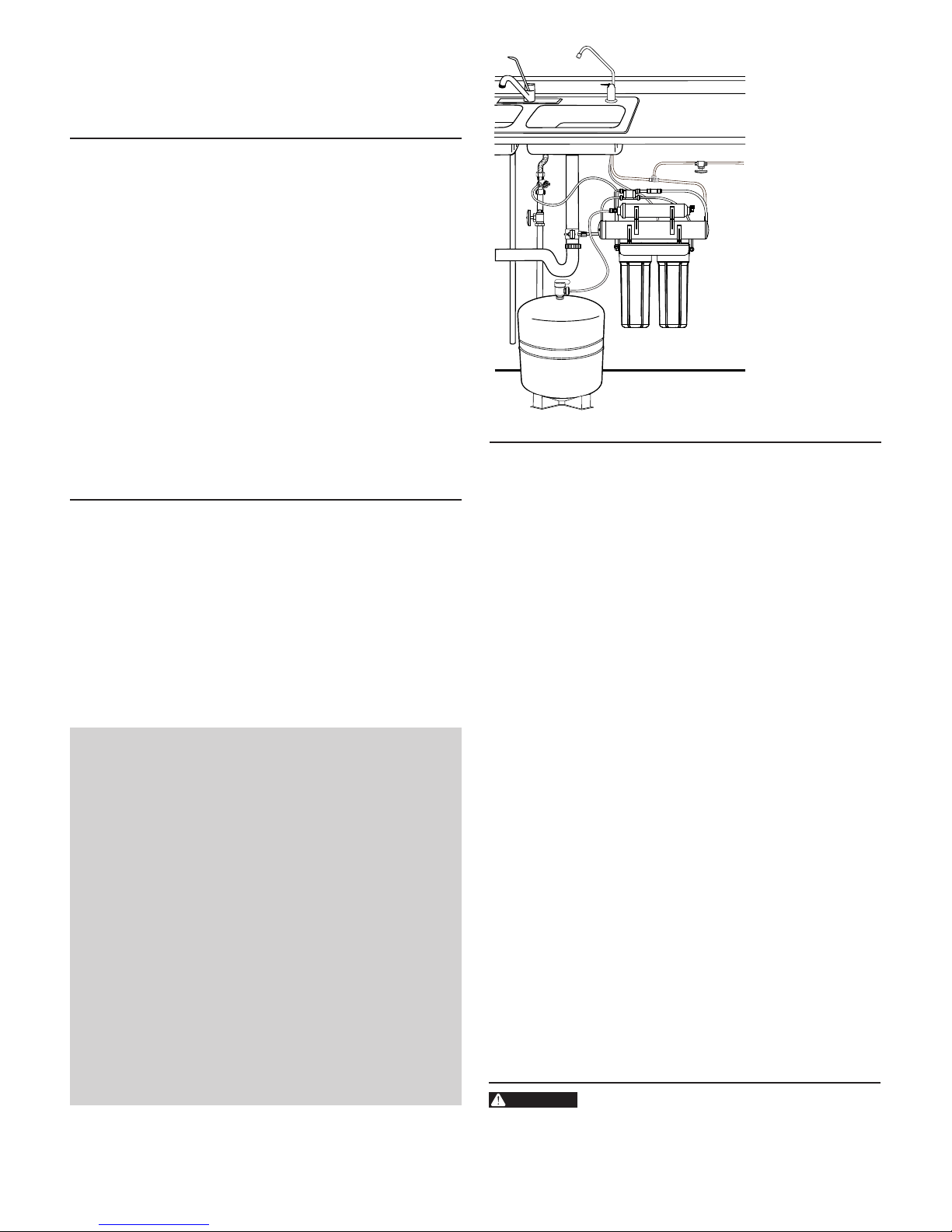
BASIC INSTALLATION PROCEDURE GUIDELINES
• For standard, under-sink installation on 3/8-inch (10 mm)
steel, brass, or copper cold water line.
• Please read all instructions and precautions before installing
and using your GRO-2550.
• Numbered diagrams correspond with numbered steps.
INSTALLATION
• Read all installation and operating instructions before
installing and using your RO system.
• Numbered diagrams correspond with numbered steps.
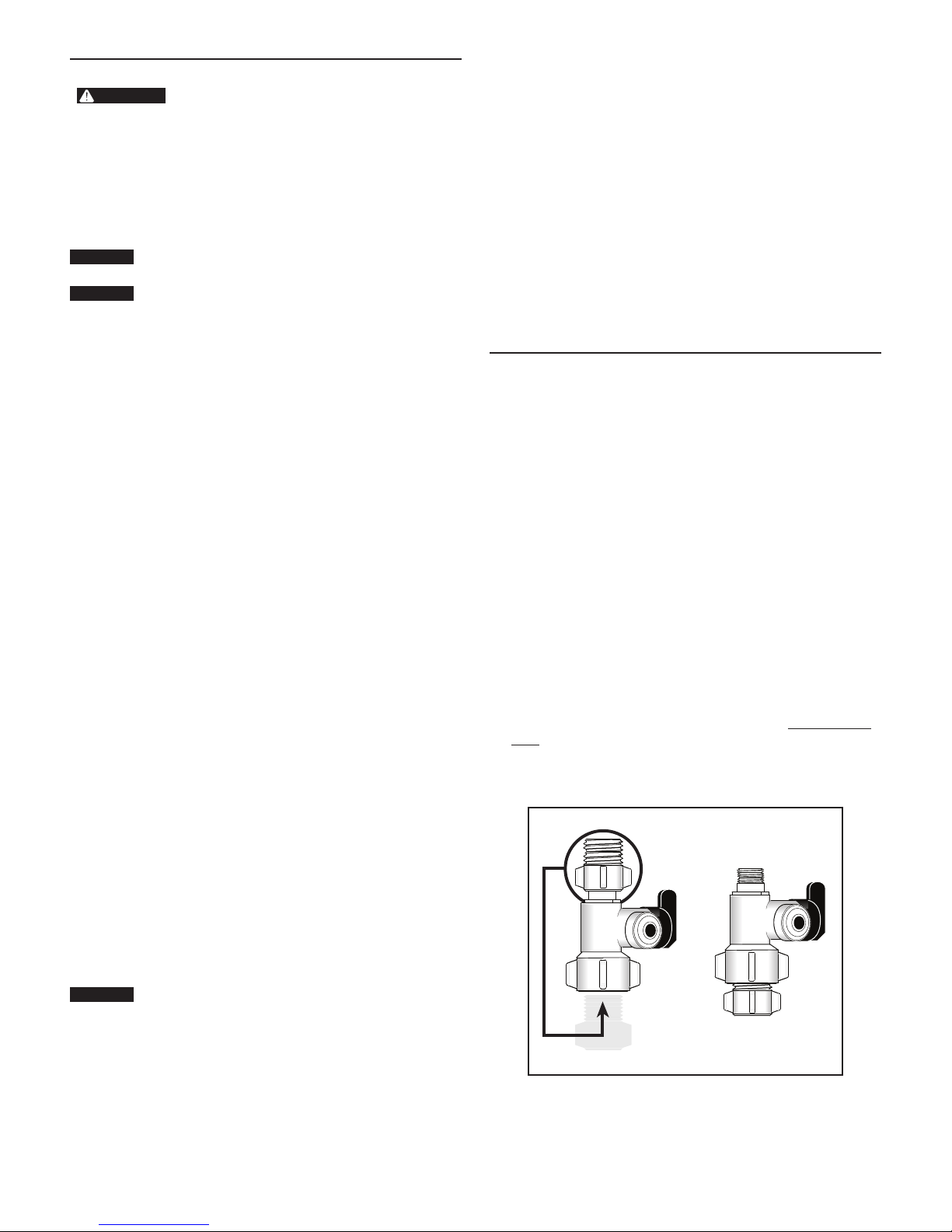
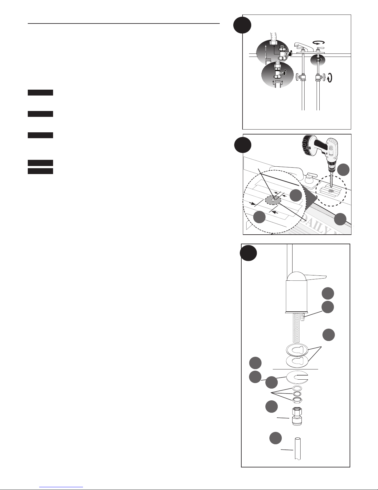
1. Installing the Water Supply Adapter
The supply adapter fits 1/2"-14 NPS supply threads or
3/8" x 3/8" compression. If local codes permit, it may be used
to connect the system to the cold water supply line. If local
codes do not permit the use of the supply adapter, alternate
connectors can be obtained from your local supplier.
Directions:
(A) Turn off cold water supply line. If cold water line does not
have a shut-off valve under the sink, you should install one.
(B) Turn on the cold water faucet and allow all water to drain
from line.
(C) Disconnect riser cold water supply valve.
(D) Ensure the sealing gasket is fully seated into the feed
adapter valve female thread.
(E) Install feed adapter valve onto supply valve as desired. The
feed adapter valve may be installed at the bottom of the
supply hose or the top of the cold water line. Hand tighten
only.
(F) Connect the riser to the feed adapter valve.
NOTE: Be careful not to cross-thread.
RO MEMBRANE PRECAUTIONS
Chlorine will destroy the GRO-EN reverse osmosis
element. If you use the GRO-2550 with a chlorinated
or periodically-chlorinated water supply, it is
ABSOLUTELY NECESSARY to use a carbon pre-filter
(included with the system). The carbon pre-filter
should be changed at least every 6-12 months to
avoid chlorine bypass. See Warranty for disclaimers
and limitations that apply to the GRO-50EN element.
4 • GRO2550 Installation and Operation Manual
INSTALLATION CONTINUED . . .
CAUTION:
CAUTION:
CAUTION:
CAUTION:
CAUTION:
1
2. Selecting the Faucet Location
The drinking water faucet should be positioned with function, convenience
and appearance in mind. An adequate flat area is required to allow faucet
base to rest securely. The faucet fits through a 1
pre-drilled 1
drinking water faucet may be installed using one of these holes, despite their
larger size. If these pre-drilled holes cannot be used or are in an inconvenient
location, it will be necessary to drill a 1
countertop next to the sink for the faucet.
The following instructions apply to stainless steel sinks ONLY.
(A) Line bottom of sink with newspaper to prevent shavings, parts or tools
from falling down the drain.
(B) Place masking tape over the area to be drilled to help prevent scratches if
drill bit slips.
(C) Mark point with center punch. Use a 1/4-inch drill bit to drill a pilot hole
through sink.
(D) Use a 1
1
⁄2-inch or 13⁄8-inch diameter holes designed for spray hoses. The
1
⁄4-inch hole in the sink or through
This procedure may generate dusts which can cause severe
irritation if inhaled or come in contact with the eyes. The use of
safety glasses and safety mask for this procedure is recommended.
Do not attempt to drill through an all-porcelain or porcelain-coated
sink. For applications on these types of sinks, we recommend using
the sprayer hole or mounting the faucet through the countertop.
When drilling through a countertop, make sure the area below the
drilled area is free of wiring and piping. Make certain that you have
ample room to make the proper connections to the bottom of the
faucet.
Do not drill through a countertop that is more than 1 inch thick.
Do not attempt to drill through a tiled, marble, granite or similar
countertop. Consult a plumber or the countertop manufacturer for
advice or assistance.
1
⁄4-inch hole saw to enlarge hole. Smooth rough edges with a file.
1
⁄4-inch hole. Most sinks have
3. Mounting the Faucet
(A) Loosen stem-nut on faucet, remove metal slotted disc (if attached).
(B) Attach large diameter 3/8-inch drain tube to barb fitting at the faucet base.
This tube should be long enough to reach the drain clamp in Step 4.
(C) Locate the small diameter 1/4 inch drain tube connected to the drain
port of the GRO element. Route the tubing to the faucet and cut off the
excessive length of tubing. Retain extra tubing for connecting storage tank
to RO system.
(D) Attach 1/4 inch drain tubing from RO system to other barb fitting at faucet.
(E) Slide chrome plate and black rubber washer onto faucet by threading both
drain tubes through the holes on the plate and washer.
(F) Slide white extension onto long threaded section of faucet. Open end of
extension should come in contact with base of faucet.
(G) Apply 3-5 wraps of plumber tape to faucet stem. Screw quick connector
onto end of threads.
(H) Wet end of 3/8" tube. Push into bottom of connector. Tug gently to be sure
connection is complete.
NOTE: To remove the tube, push on the fittings' collar and pull the tube out.
(I) Holding the faucet, feed the three tubes through the hole in the sink.
Position the faucet handle at a desired location
(J) Center the faucet and slip slotted disc between the white extension and the
bottom of the counter or sink. Tighten the stem nut with a wrench until it is
tight.
(K) Firmly insert goose-neck spout into faucet base.
2
Pilot Hole
D
3
B
C
1/4"
1
4”
⁄
C
1
⁄4"
1
11⁄
4”
D
Mounting
Hole
A
B
C
D
Counter Top
A
I
E
F
4. Installing the Drain Clamp
NOTE: If you have a single-basin sink with a disposal unit, call Technical
Support for options.
NOTE: Before installing the drain clamp, check the drainpipes under the sink
G
GRO2550 Installation and Operation Manual • 5
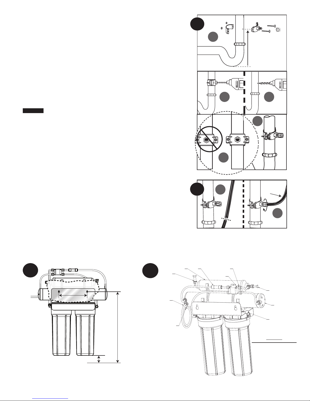
for corrosion. Corroded pipes should be replaced before continuing with
CAUTION:
5
6
7
installation.
(A) Attach the drain clamp to a vertical section of the drainpipe, about 6 inches
above the trap. Make sure the opening on the drain clamp is facing towards the
drinking water faucet (see diagram on previous page).
(B) Using the fitting hole of the drain clamp as a guide, drill a 1/4-inch hole
through one side of the drainpipe.
(C) Remove the drain clamp from the drainpipe and enlarge the hole with a
3/8-inch drill bit. Use a file to remove rough edges from the drilled hole.
(D) Make sure the black rubber gasket is adhered to the inside of the drain clamp
and place the drain clamp assembly over the drilled hole. Look through the
hole and position the clamp so that the center of the clamp hole is slightly
higher (about 1/16-inch) than the center of the drilled hole. Tighten the clamp
securely.
(E) Screw the plastic compression nut onto the drain clamp until hand-tight.
5. Connecting the Faucet to the Drain
This is a gravity drain line. Any loops, kinks or sharp bends must be
eliminated before proceeding. Failure to create a straight line to the
drain may result in reject water leaking through the air gap in the faucet
onto the countertop and below the faucet.
(A) Align the larger reject (3/8-inch) tubing from the faucet with the compression
nut on the drain clamp. Create as straight and smooth a path as possible with
the tubing. Do not kink tube. Cut the tubing squarely below the nut and remove
the internal and external burrs.
(B) Loosen the compression nut two complete turns. Insert the tubing into the nut
until it stops. Tighten with fingers, then tighten 1 to 2 turns with a wrench.
4
A
6"
B C
E
D
6. Installation of Mounting Screws
(A) If system is being installed under the kitchen sink, locate it on back or right
wall. Make sure to allow ample space for installation. To change the filter
cartridges, a minimum of 1-1⁄2 inches of clearance is required underneath the
filter housings. A minimum of 2 inches of clearance from the left side of the
unit is also required or 5 inches from the left bracket mounting screw hole.
1
(B) Install mounting screws at least 15 inches from cabinet floor and 7
⁄2-inches
apart. Leave a 5/16-inch space between the head of the screw and the wall to
slip bracket onto screws.
NOTE: Each connection fitting on the RO Assembly has a plug that must be
removed before inserting tubing. Push in on the collar and pull the plug
out.
7. Connecting the Faucet to the System
(A) The faucet tube from the bottom of the threaded metal tube is inserted into the
post filter. The fitting is at the top right of the RO System. Push the free end of
the tubing into the quick connect fitting.
POST
FILTER
TO DRAIN
7 1/2”
15”
(minimum)
to oor
TO FAUCET
FLOW
RESTRICTOR
CHECK
VALVE
A
NOTE:
SCREW HEADS THIS SIDE UP
AUTO
SHUT OFF
VALVE
3/8" Tube
B
TO TANK
RO
MEMBRANE
INLET WATER
1 1/2” (minimum) to oor
6 • GRO2550 Installation and Operation Manual
CARBON
CARTRIDGE
TUBING CONNECTION DIAGRAM
SEDIMENT
CARTRIDGE
BACK VIEW
INSTALLATION CONTINUED . . .
CAUTION:
CAUTION:
CAUTION:
10
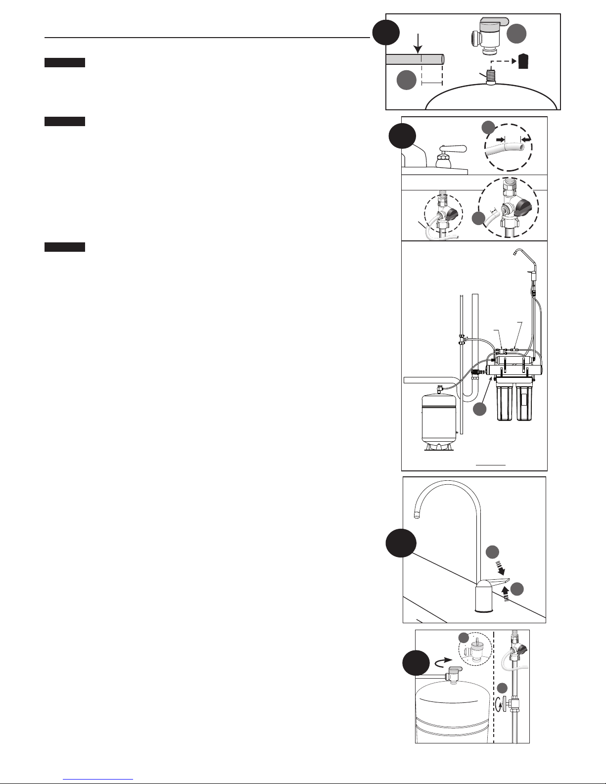
8. Connecting the Storage Tank to the System
When tank is full, it weighs approximately 28.5 lbs. (12.9 kg) Provide
ample support under the tank.
(A) To prevent leaks, apply 3 or more wraps of plumber tape to threads on tank.
Thread the tank valve onto the top of the tank opening. Turn tank so handle is
in line with tubing.
The tank/valve connection will leak if not properly sealed. plumber tape
will normally seal the threaded connection.
(B) Locate the remaining length of 1/4-inch tubing. Place a mark on the tubing
5/8-inch from one end. Moisten the marked end of the tubing with water and
insert with a twisting motion into the port of the tank valve until the 5/8-inch
mark is flush with the quick connect fitting. Then locate the tank near the
system's installation area.
(C) Cut the tubing to correct length. Install free end of tubing into white quick-
connect fitting on the post filter tee on the left side. Ensure the tubing does
not kink.
(D) Place entire system over mounting screws on wall and slide down.
Make certain system is firmly attached to wall to prevent it from falling
and possibly becoming damaged.
NOTE: Use caution not to bend or pinch the tubing behind the system while
attaching to mounting screws.
8
1/4" Tube
B
9
1/4”
Tube
5/8"
Apply
plumber
tape
C
A
5/8”
16mm
5/8”
16mm
A
FAUCET
9. Connecting the System to the Water Supply Adapter
(A) Locate remaining length of 1/4-inch plastic tubing.
(B) Place a mark on the tubing 5/8-inch from the end. Moisten the end of the
tubing with water and insert with a twisting motion push into quick connect
fitting on the left side of system. Depending on the installation, the system
may need to be removed from the mounting surface to access the left side of
the system.
(C) Cut the tube to a length that will allow connection to the Water Supply
Adapter. Ensure the tubing does not kink. Place a mark on the tubing
5/8-inch from the end. Moisten the end of the tubing with water and insert
with a twisting motion push into quick connect fitting on the Water Supply
Adapter.
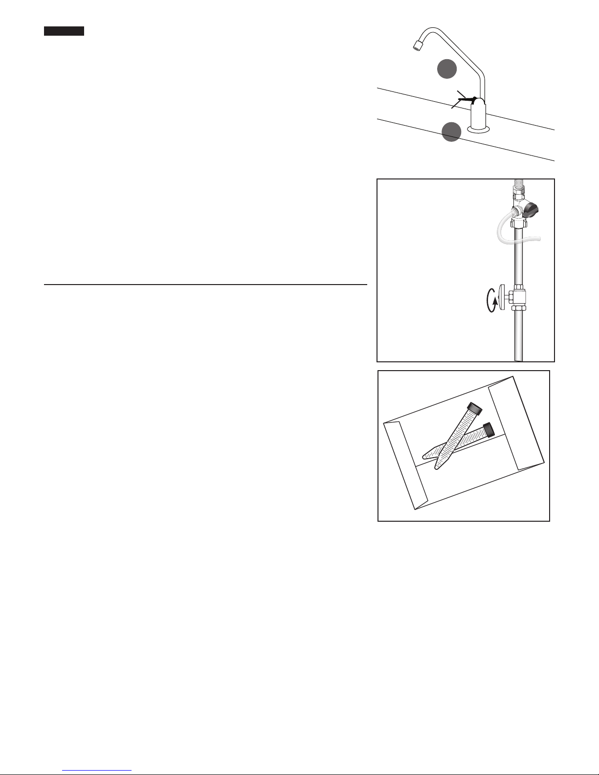
10. Faucet Operation
(A) For controlled water flow, push the handle down.
(B) For constant water flow, lift the faucet handle to lock it in the open position.
11. System Start-up
NOTE: The reverse osmosis membrane is treated with a food grade sanitizing
agent that may cause an undesirable taste. Although it is not harmful, it
should be flushed from the system.
NOTE: The post-polishing filter may contain fine black carbon particles. These
fines are harmless, but may make the water appear gray in color. The
carbon fines are flushed from the system with the first tank full of water.
NOTE: The RO system does not produce a high volume of water on demand as an
ordinary filter does. Water is produced at a slow, drop-by-drop rate. The
system requires about 2 to 4 hours to fill the storage tank. As water is taken
from the tank, the system automatically starts the cycle of replacing the
water and then stops water production when the tank is full.
DRAIN
TANK
INLET
WATER
AUTO
SHUT OFF
VALVE
B
SEDIMENT
CARTIRDGE
FRONT VIEW
A
CHECK
VALVE
CARTRIDGE
Push Down
B
CARBON
Push Up
Closed Tank Valve
11
A
Open
Tank Valve
B
Counter-
clockwise
GRO2550 Installation and Operation Manual • 7
CAUTION:
Visually check the entire system for leaks.
Troubleshooting on page 11.
(A) Turn off valve at top of storage tank.
(B) Turn on the cold water supply, and ensure the supply adapter valve is open.
(C) Lift the faucet handle to lock it in the open position and let it drip for 30 min.
(D) Completely open the cold water supply until it comes to a stop. Allow water
to drip from the faucet for 12 more hours. Then close the faucet and open the
valve on the storage tank. The tank valve is open when the handle lines up with
the tubing connection.
(E) Allow 3 hours for the tank to fill. Continue to periodically check the installation
for leaks. After the storage tank is filled, open the faucet to flush the post-filter
cartridge. Allow 4 to 5 minutes for all of the water to drain from the tank. Close
faucet and allow tank to fill.
(F) Repeat step E four times.
NOTE: Initially, the water may appear cloudy. This is a result of air trapped in the
post-polishing filter. It is not harmful and will disappear in a matter of
minutes. It may take up to a week after installing a new post-polishing filter
for the trapped air to dissipate.
The system is ready for operation. You can now enjoy quality water from your
Reverse Osmosis System.
If a leak is present, see
A
Push Down
Push Up
B
TESTING YOUR REVERSE OSMOSIS SYSTEM
Model GRO-2550 Reverse Osmosis System
Total Dissolved Solids (TDS) Test
NOTE: It is highly recommended that you (the consumer) have your water
tested at least every 6 months to verify that your system is performing
satisfactorily.
SAMPLING INSTRUCTIONS:
Sampling instructions are included with the Total Dissolved Solids (TDS) Test Kit.
Counter-clockwise
Total Dissolved
Solids Test Kit
8 • GRO2550 Installation and Operation Manual
OPTIONAL INSTALLATION
CAUTION:
CAUTION:
6
5
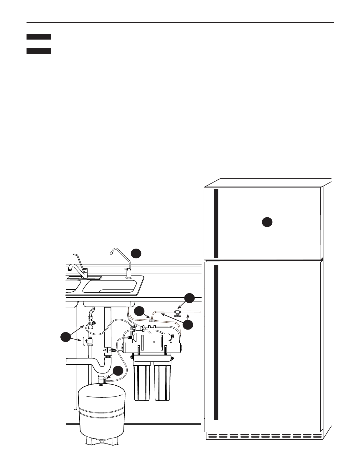
Connecting your Reverse Osmosis System to Refrigerator Icemaker / Water Dispenser
If you are connecting this unit to your refrigerator/icemaker with initial RO installation, wait to turn on the icemaker until
the post-polishing filter has been flushed according to Step 11.
Use plastic tubing and fittings. Do not use copper tubing or brass fittings.
For optimum performance, it is recommended that the distance between the RO system and the refrigerator icemaker/water
NOTE:
dispenser be no greater than 10 feet (3 m). At distances greater than 10 feet, the water pressure from the system may not be
adequate to deliver water to the refrigerator.
MATERIALS REQUIRED (available from your local hardware store):
• 3/8-inch x 3/8-inch x 3/8-inch (0.952 cm x 0.952 cm x 0.952 cm) compression or quick-connect tee
• 10 feet (3 m) of 3/8-inch (0.952 cm) polyethylene tubing
• Shut-off valve
1. Turn off refrigerator water supply and icemaker (consult manufacturer’s guidelines).
2. Close tank valve (on top of storage tank).
3. Turn off water to RO system at the cold water supply, or at the feed water supply adapter.
4. Open drinking water faucet to relieve pressure.
5.
Locate tubing (permeate) leading to your drinking water faucet. Cut and insert the
3/8-inch
Consult manufacturer’s guidelines before installing the supply adapter.
NOTE: When cutting the permeate tubing, you may experience some water leakage.
6. Using a length of 3/8-inch polyethylene tubing, connect the
icemaker/dispenser line with the free port on the compression tee.
7. The shut-off valve should be installed as close to this port of the tee
as possible. Shut-off valve should be installed in the OFF position
Consult manufacturer’s guidelines before installing the shut-off valve.
8. Completely open cold water supply.
9. Open tank valve.
10. Turn off the drinking water faucet.
11. Turn on water to RO system at cold water supply.
12. Turn on icemaker and open shut-off valve.
Consult manufacturer’s instructions.
13. Check for leaks and tighten connections if necessary.
x
3/8-inch
x
3/8-inch
compression or quick-connect tee into the permeate tubing.
1
4
7
3
2
GRO2550 Installation and Operation Manual • 9
CAUTION:
CAUTION:
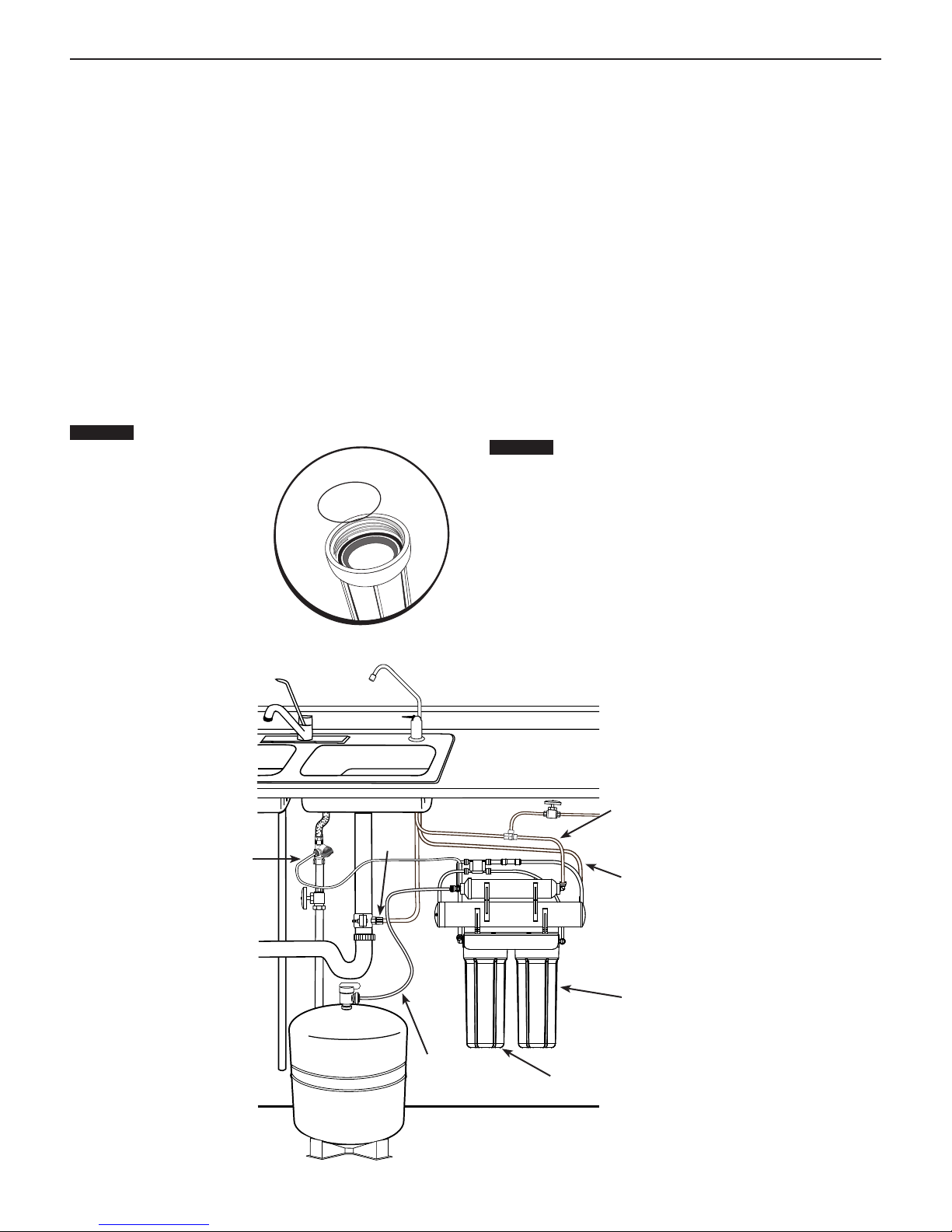
REPLACING THE PREFILTER AND POSTFILTER CARTRIDGES
1st Stage Pre-Filter and 2nd Stage Pre-Filter Cartridges:
The cartridge should be replaced every 6-12 months. If your
water contains a high amount of sediment, it may be necessary
to change the 1st stage cartridge more frequently. If your water
contains a high amount of chlorine, it may be necessary to
change the 2nd stage pre-filter more often.
1. Turn off incoming water supply and valve on the storage
tank. Place a tray under the system to catch any water that
spills during removal of the filter housings.
2.
Open faucet to release pressure.
3.
Unscrew bottom of filter housings from caps. Use the filter
wrench. Discard used cartridges.
4. Remove black rubber O-rings from grooves in housings.
Wipe grooves and O-rings clean; set O-rings aside.
5. Rinse out housings and fill each 1/3 with water. Add 2
tablespoons of
sponge. Rinse thoroughly.
Lubricate each O-ring with a coating of clean silicone grease.
6.
bleach and scrub with non-abrasive brush or
With two fingers, press each O-ring securely into groove
below the threads of the appropriate housing.
The rubber O-ring provides the
water-tight seal between
the cap and the bottom
of the housing. It is
important that the
O-ring be properly
seated in the groove
below the threads
of the housing or
a water leak could
occur.
7. Insert cartridges in the bottom of the housings. Make sure
cartridge slips over standpipe in the bottom of the housing.
NOTE: Be sure to install cartridges in proper housings (see diagram
below).
8. Screw bottoms of housings back onto caps securely; do not
over-tighten. Turn on cold water supply.
Check for leaks. Continue to check periodically to make sure
no leaks develop.
4th Stage Post-Filter Cartridge: post-filter should be replaced
every twelve months.
1. Turn off incoming water supply and valve on the storage
tank. Place a tray under the system to catch any water that
spills during removal of the filter housings.
Open faucet to release pressure.
2.
3. Remove filter from bracket and discard.
4. Remove tubes from fittings by pressing in collar around the
fitting while pulling the tubing out with your other hand.
NOTE:
If quick connect fittings need to be installed, tape
threads of fittings with 3 wraps of plumber tape and
attach to filter.
Ensure the tape is not touching O-ring on the fitting
or a leak may occur.
NOTE:
The filter has an arrow on it showing the direction of
flow. The tee fitting connects to the inlet side of the filter
and the elbow fitting attaches to the outlet side.
NOTE:
Hand tighten fittings, then tighten with wrench 1/4 turn.
5. Attach 4th stage filter to bracket with the tee fitting on the
right hand side.
6. Attach tubes to fittings by pushing in until the tube stops.
Check to see if tube is in place by trying to gently pull tube out.
1/4" Feed Tube
10 • GRO2550 Installation and Operation Manual
3/8"
Drain
Tube
1/4" Storage
Tank Permeate
Tube
3/8" Faucet Permeate Tube
1/4" Faucet Drain Tube
Carbon (2nd Stage) Prefilter
Sediment (1st Stage) Prefilter

CAUTION:
REPLACING THE 3RD STAGE REVERSE OSMOSIS MEMBRANE
About the Reverse Osmosis Membrane
When used under operating conditions specified on page 1 of
the manual, your reverse osmosis membrane should last at
least one year. You should replace the membrane after 18 to 24
months. Replace it sooner if you notice a return of unpleasant
tastes or odors or a noticeable decline in water production. The
precise life span of your system's membrane will depend on
the quality of the water entering the system and the frequency
with which you use it. Frequent system use prevents the
filtered salts and minerals from building up on the membrane
as scale. The more water the system is required to produce,
the longer the membrane will last. You may wish to find a
variety of uses for your system in order to prolong the life of the
membrane.
NOTE: If system stands for more than 2 to 3 days without being
used, the storage tank should be emptied.
Replacing the Membrane and Filters
NOTE: When installing a new GRO membrane element and flow
control, it is recommended that you replace the prefilter and post-filter cartridges as well.
1. Turn off the cold water supply. Allow five minutes for
system to depressurize.
Place a tray under the system to catch any water that spills
during removal of the filter housings.
2. Open drinking water faucet to drain tank. When tank is
drained, close faucet.
3. Disconnect the tubing connections from the GRO element.
Install the new GRO element, permeate checkvalve, and
capillary reject flow controller.
4. Unscrew filter housings from caps and discard used
cartridges.
5. Remove black rubber O-rings from grooves in housings.
Wipe grooves and O rings clean.To replace the filters, see
Replacing the Pre-Filters and Post-Filter on page 9.
6. Lubricate O-rings with a coating of clean silicone grease.
With two fingers, press each O-ring securely into groove
below the threads of the appropriate housing.
The rubber O-ring provides the water-tight seal
between the cap and the bottom of the housing. It is
important that the O-ring be properly seated in the
groove below the threads of the housing or a water
leak could occur.
NOTE: After installing new GRO element, flow control, and
cartridges, allow system to run for 3 hours to fill tank.
Check for leaks every hour. As pressure builds in
tank, leaks may occur that did not exist directly after
installation. When the RO element and cartridges have
been changed, follow the system start-up procedure in
Step 11: System Start-up.
Sanitization Procedure
1. Turn off the water supply to the RO system and open the RO
faucet to drain the storage tank.
2. Disconnect the tube from the shut off valve on the storage
tank.
3. Using a clean eye dropper, insert 1/2 teaspoon of common
household bleach into the blue tube. This will flow into the
tank once water is turned back on to unit. Reattach tube
to the shut off valve on the storage tank. Follow start up
procedure.
GRO2550 Installation and Operation Manual • 11

TROUBLESHOOTING GUIDE
Leaks between bottom of housing and cap
1. Ensure sump is tightly screwed to cap. If it still leaks close
the cold water supply and tank valves.
2. Clean black rubber O-ring and lubricate with clean silicone
grease. With two fingers, insert O-ring in groove below
threads of housing and press into place. Tighten housing
back onto cap.
3. Open the cold water supply and tank valve.
If leaks persist, call Technical Support.
Leaks on tank valve assembly
1. Open drinking water faucet to drain storage tank. Let
drinking water faucet run until it drips. Turn off cold water
supply.
2. Push in on white collar of tank valve fitting and pull out
tubing. Unscrew the tank valve from the storage tank.
Rewrap threads on top of the tank with plumber tape. Screw
tank valve back onto tank. Trim 1/2-inch from end of tubing
and reinsert 5/8-inch into tank valve fitting.
3. Open the cold water supply and shut off the reverse osmosis
faucet. Let the system pressurize for several hours and
check for leaks. Check again after tank is fully pressurized.
Leaks on quick-connect fittings
1. Close the cold water supply and tank valve.
2. Depress plastic collar and pull out tubing.
3. Cut off 1 inch of tubing and place a mark 5/8-inch from end
of tubing. Tubing should be cut squarely. The internal and
external burrs should be removed.
4. Push tubing 5/8-inch into fitting.
5. Open the cold water supply and tank valve. If leaks persist,
call Technical Support.
Gradual return of taste and odor
Gradual return of unpleasant taste and odor over a period
of time may indicate that your filter cartridges and/or RO
membrane need to be replaced.
on page 9
page 10.
and Replacing the Reverse Osmosis Membrane”on
See Replacing the Pre-Filters
Sudden return of taste and odor
If shortly after complete servicing noticeable taste and odors
return contact Technical Support.
No water pressure from the drinking water faucet
or low volume in storage tank
1. Close the cold water supply to system.
2. Lift storage tank to see if it is empty. If not, open the drinking
water faucet to empty water from tank.
NOTE: It may be necessary to pump a small amount of air into
the tank with a bicycle pump to remove all the water
from the tank.
3. When tank is empty, use a pressure gauge to check
tank pressure. An empty tank should contain 5 to 7 psi
pressure. Increase or decrease the air pressure in the tank
accordingly.
4. Open cold water supply. Let system run for 3 hours to fill
tank, then check system performance. If performance has
not improved, call Technical Support.
No flow or slow flow from the brine (drain) line
Less than 1½ cups per minute
NOTE: Before checking brine (or reject) flow, make sure the
system is producing water by turning off the valve on the
storage tank and opening the faucet. Water should drip
from faucet.
1. Examine the pre-filters. If clogged, replace (see Replacing
the Pre-Filters and Post-Filter on page 9) and recheck the
brine (or reject) flow rate.
2. If the pre-filters are not at fault, the brine (or drain) flow
controller is probably clogged. Call Technical Support.
High TDS in Product Water
If high levels of TDS (Total Dissolved Solids) are detected in
your product water (approximately 30% or greater of what is
measured in your tap water, as determined with a conductivity
meter or by the supplied TDS Test Kit), the GRO membrane
element may need to be replaced, or the brine (or drain) flow
control tubing may be clogged. See your dealer or plumber to
check product water TDS.
Reduced production
Slow or no product water flow usually indicates either a
clogged pre-filter or an exhausted membrane. First, replace
the pre-filters. If the production rate is not improved, replace
membrane.
12 • GRO2550 Installation and Operation Manual
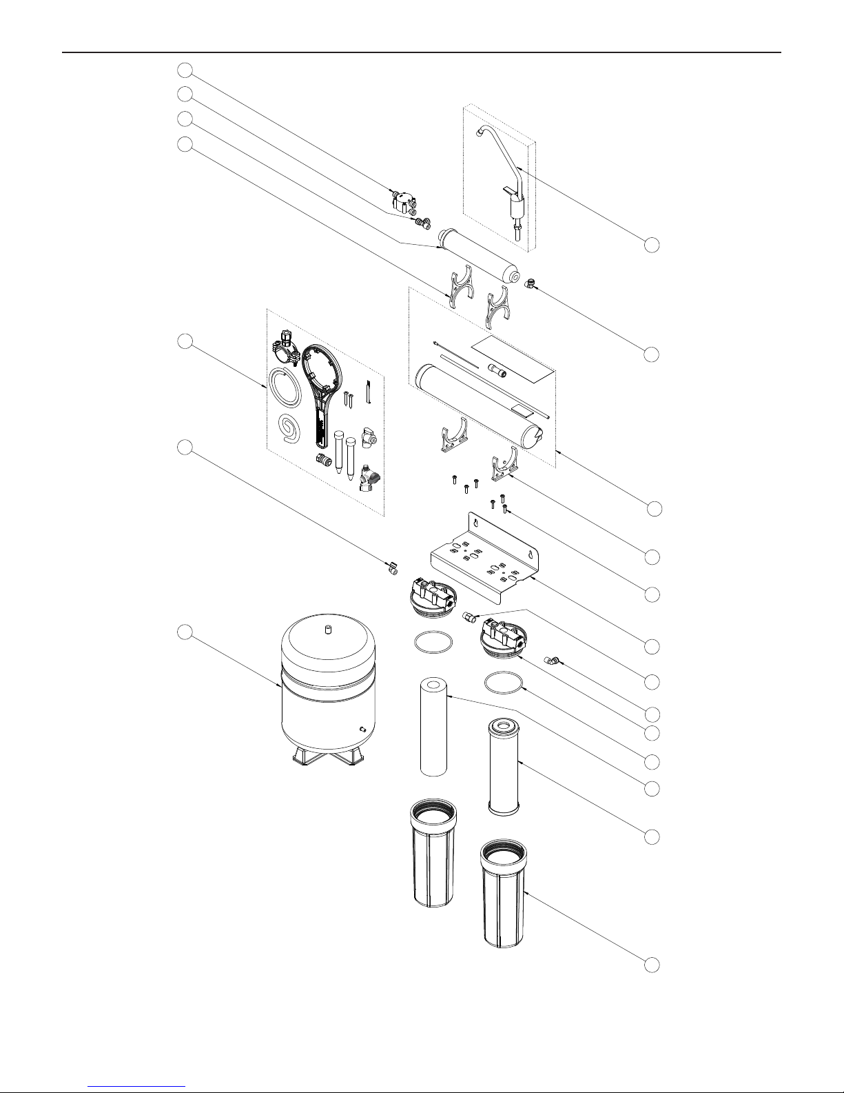
PARTS GUIDE
19
18
17
16
1
15
8
14
2
3
4
5
6
7
8
9
For replacement parts, contact your nearest Water Filter dealer or call 800.279.9404
10
11
12
13
GRO2550 Installation and Operation Manual • 13
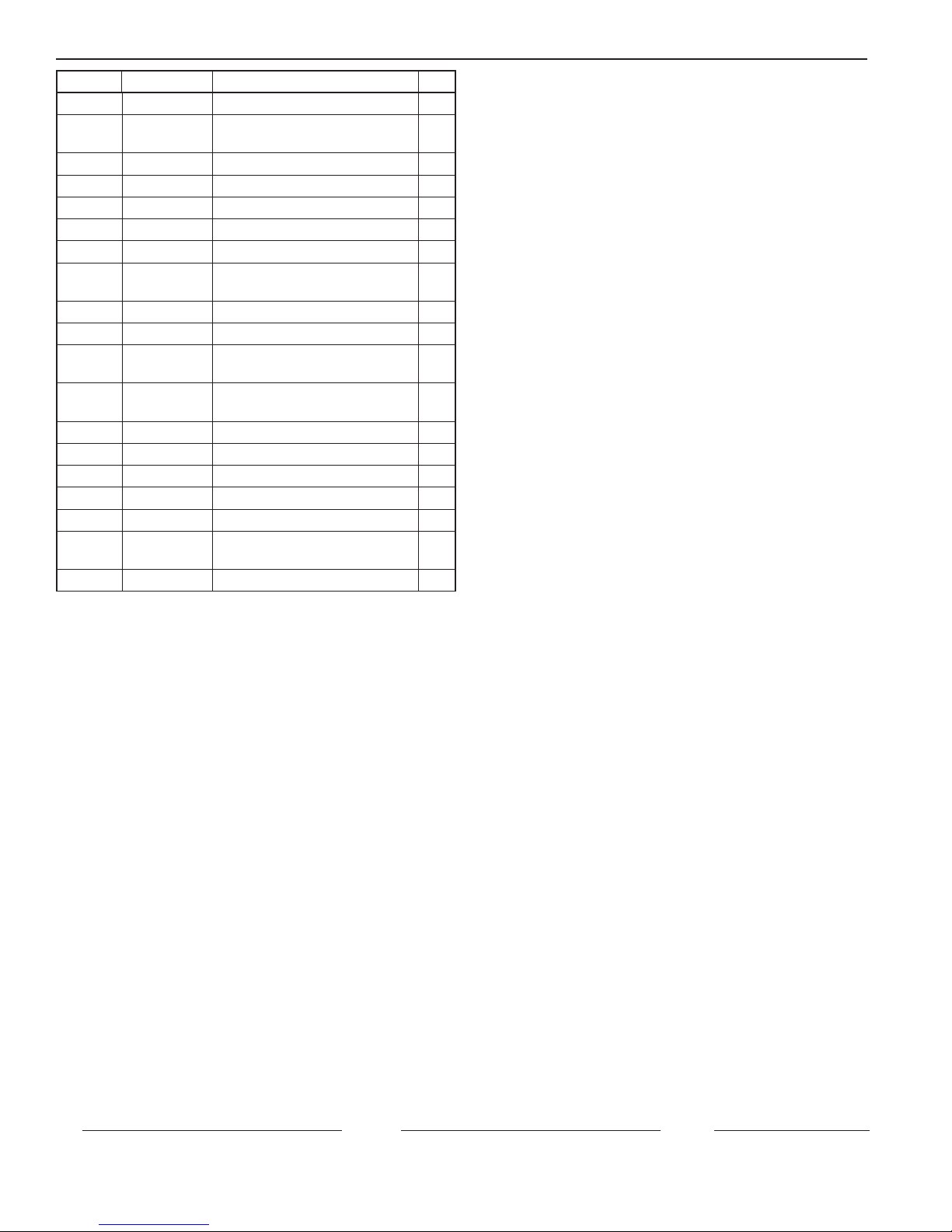
PARTS GUIDE CONTINUED . . .
ITEM NO. PART NO. DESCRIPTION QTY
1 244820 FAUCET 1
2 244834 ELBOW, 3/8" TUBING QUICK
CONNECT
3 4004424 STAGE 3, GRO-EN W/DLFC 1
4 BPRO-50-S17 CLIP, SINGLE 2
5 PW-80-09 BRACKET SCREW 6
6 244784 BRACKET, STEEL 1
7 244791 NIPPLE, 1/4" NPT X 1/4" NPT 1
8 244788 ELBOW, 1/4" TUBING QUICK
CONNECT
9 154062 CAP, SL, 1/4" NPT 2
10 143026 O-RING, SUMP 2
11 155014-43 STAGE 1, SEDIMENT PRE-FILTER,
5 MICRON
12 155634-43 STAGE 2, CARBON BLOCK PRE-
FILTER
13 153049 #10 SUMP, WHITE 2
14 244833 RO STORAGE TANK 1
15 244982 INSTALLATION KIT, GRO SYSTEM 1
16 BPRO-50-S18 CLIP, DOUBLE 2
17 255521-43 STAGE 4, GAC POST FILTER 1
18 244790 TEE, 1/4" NPT X 1/4" TUBING
QUICK CONNECT
19 244787 VALVE, AUTO SHUT-OFF 1
1
2
1
1
1
Buyer Seller Date
14 • GRO2550 Installation and Operation Manual
 Loading...