

Pentair Goyen Precision PS-L, Goyen Precision PS CA, Goyen Precision P2, Goyen Precision PS-LA, Goyen Precision P-CTX Installation And Operating Instructions Manual
...Page 1

PENTAIR CLEAN AIR SYSTEMS
FILTER CLEANING
SYSTEM CONTROLS
PRECISION
®
INSTALLATION AND OPERATING INSTRUCTIONS
Page 2

02 INSTALLATION AND OPERATING INSTRUCTIONS PRECISION® FILTER CLEANING SYSTEM CONTROLS
PRECISION
FILTER CLEANING SYSTEM CONTROLS
TABLE OF CONTENTS
Warning .......................................................................................................................................................................................
3
Precision Program Commissioning Log ..................................................................................................................................... 3
Product Description .................................................................................................................................................................... 3
Identifying the Parts ................................................................................................................................................................... 4
Installation – General ................................................................................................................................................................. 6
Mechanical ................................................................................................................................................................................... 6
Electrical Installation ................................................................................................................................................................... 6
Installation – Optional Accessories ............................................................................................................................................ 12
P-CTX: I/O Card ............................................................................................................................................................................ 12
P-MOD: Modbus Communications Card .................................................................................................................................... 13
Operation .................................................................................................................................................................................... 14
Powering Up the System ............................................................................................................................................................. 14
The Display and Interface ............................................................................................................................................................ 14
Manual Activation of Solenoid Outputs ....................................................................................................................................... 14
Programming and Advanced Features ....................................................................................................................................... 15
P1 – Continuous Control .............................................................................................................................................................. 15
P2 – Enhanced Demand Control ................................................................................................................................................. 16
Messages and Alarms ................................................................................................................................................................ 18
Messages ...................................................................................................................................................................................... 18
Troubleshooting .......................................................................................................................................................................... 20
General/Startup ............................................................................................................................................................................ 20
Operational ................................................................................................................................................................................... 21
P-MOD Modbus Communications .............................................................................................................................................. 21
Precision System Specifications ................................................................................................................................................ 22
Installation and Operating Instructions
Owner's Records for P1, P2, PS-L, PS-C, PS-LA, PS_CA, P-CTX and P-MOD
Deine-007
© Copyright by Pentair International Ltd. 2014
This manual is provided as an aid to owners of a Pentair Clean Air Systems instrument and contains information proprietary to Pentair Clean Air Systems.
This manual may not, in whole or part, be copied, or reproduced without the express written consent of Pentair Clean Air Systems.
Goyen Controls Co Pty Ltd reserve the right to change product designs and specifications without notice.
Rev02 – November 2014
Page 3

03INSTALLATION AND OPERATING INSTRUCTIONS PRECISION® FILTER CLEANING SYSTEM CONTROLS
WARNING
To avoid product malfunction or electrical shock, do not expose Precision circuit boards to rain or moisture. Installation must be
performed using qualified technicians.
CAUTION
Use of controls or adjustments or performance or procedures other than those specified in this manual may result in product
failure, or poor product performance. You are cautioned that any changes or modifications to the product not expressly approved
in this manual could void your product warranty.
Note
The P1, P2, PS-L, PS-C, P-CTX and P-MOD have been tested and found to comply with EN55024:1998, EN61000-4-2, EN610004-4, EN61000-4-5 and EN61000-4-11 for immunity to ESD, immunity to EFT and bursts, immunity to surges and immunity to
voltage dips and interruptions. This equipment did not become dangerous or unsafe as a result of the application of the tests
defined in EN55024:1998.
PRECISION PROGRAM COMMISSIONING LOG
Use this log during system commissioning to keep a permanent record of controller settings.
PARAMETER DEFAULT
Language English
On time (ms) 100
Off time (s) 50
Display units* kPa
Demand cleaning*
(by limits; default)
High dP
Low dP
1.0 kPa
0.5 kPa
Demand cleaning*
(by bandwidth)
High dP
% band
1.0 kPa
40
Alarm delay(s) * 0
High dP alarm* 2.0 kPa
Precoating* None
Pattern cleaning* Off
Blowdown cycles None
Remote stop* Hardwired
Tube cleaner CTX Off
Maximum Interval* (s) Off
Network MOD Off
* Only with P2 controllers.
CTX Available on the AC/AC baseboard, otherwise only when P-CTX fitted.
MOD Only when P-MOD fitted.
PRODUCT DESCRIPTION
The Precision (or controller) is an advanced filter cleaning control system for reverse-pulse jet dust collectors. This system
may be specified with a selection of control interfaces and signal output options. The controller may be easily upgraded from
simple sequential mode control (P1 interface) to Enhanced Demand Mode (P2 interface). An RS-485 Modbus RTU compliant
communications card (P-MOD) provides full networking and remote programming for DCS and SCADA systems. An I/O card
(P-CTX) provides voltage-free contacts for alarms, 4–20 mA output (for dP reporting, P2 only), and basic remote control. The
solenoid outputs can be expanded up to 200 outputs through the use of the PS-L or PS-C expansion cards (or slave cards) with
the AC/DC baseboard (AC voltage input, DC voltage output) or DC/DC baseboard (DC input and output) and PS-LA or PS-CA
expansion cards on the AC/AC baseboard (AC input and output).
Page 4

04 INSTALLATION AND OPERATING INSTRUCTIONS PRECISION® FILTER CLEANING SYSTEM CONTROLS
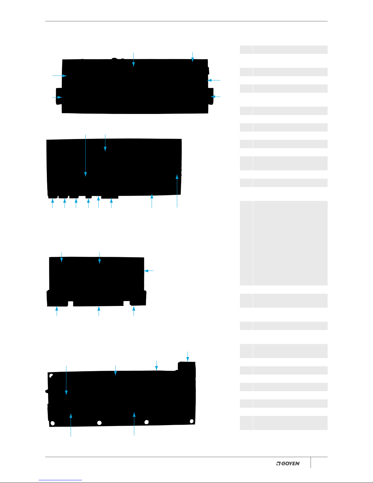
Your system may have some or all of these components. Note that terminal headers are supplied for all push-in contacts.
Figure 1:
P1 Interface and Controller, Top View
4
5
3
22
6
1278
9
23
4
5
Figure 2: Controller, Front View
71211 2010
DIRTY
CLEAN
21
Note: Controller assemblies in
Figures 1 and 2 include (left to right)
P-CTX, P-MOD and P2 interface, all
mounted on the AC/AC baseboard.
Figure 3:
PS-C, DC Output Compact Terminal Expansion Card
17
16
18
1514
13
IDENTIFYING THE PARTS
Page 5
05INSTALLATION AND OPERATING INSTRUCTIONS PRECISION® FILTER CLEANING SYSTEM CONTROLS
Figure 4: PS-L, DC Output Large Terminal Expansion Card
19
14
15
17
18
16
Figure 5: AC/AC Baseboard Top View
27
24
287
10 30 31 29 20 12
Note: AC/AC baseboard comes with the tube cleaner mounted on the baseboard.
For the AC/DC and DC/DC baseboards it comes separately on the P-CTX card.
Figure 6:
PS-CA AC output Compact Terminal Expansion Card
27
24
30
3115
17
Note: No LEDs for AC output Compact Terminal Expansion Card.
Figure 7:
PS-LA AC output Large Terminal Expansion Card
30
31
15
17
27
26
Note: All AC output products (Figures 5–7) have no manual solenoid triggers.
Key to Figures 1 to 7
1 Precision motherboard (10 output)
2 P2 Enhanced Demand Mode
interface
3 P1 Sequential Mode interface
4 Power-on switch
5 Power LED
6 Motherboard manual solenoid
triggers and LEDs.
7 Motherboard solenoid terminals
8 P-MOD, Modbus card (optional)
9 P-CTX, I/O card (optional)
10 Power in
11 Expansion card connection
12 Fan contacts
13 PS-C, compact expansion card (10
output)
14 Expansion card contacts
15 Solenoid terminals and LEDs
16 Expansion card manual solenoid
triggers and LEDs
17 Expansion card terminating
resistor and addressing switches –
Switch No.1:
Turns on terminating resistor*
Addresses 1 to 9:
Turn DIP switch No. 2 to ‘OFF’
position and use Rotary switch to
select address
Addresses 10 to 19:
Turn DIP switch No. 2 to ‘ON’
position and use Rotary switch to
select address
* Terminating resistor is turned to
‘ON’ position on last slave card.
18 Expansion card fuse
19 PS-L, large expansion card (10
output)
20 Motherboard terminating resistor
(DIP switch No. 1)
21 Pressure Transducer
22
24 V Rail Fuse – 250 V 4 A (located
on motherboard)
23
Mains Fuse – 250 V 2 A (located on
motherboard)
24 AC/AC Baseboard
25 PS-CA Compact expansion card
26 PS-LA Large expansion card
27
T3A 250 V slow-blow fuse 20 mm
28 Isolate and Purge contacts
29
24 V DC additional voltage in
30 Power to expansion cards
31 Communications with expansion
cards and baseboard
Page 6

06 INSTALLATION AND OPERATING INSTRUCTIONS PRECISION® FILTER CLEANING SYSTEM CONTROLS
MECHANICAL
The Precision may be supplied as PCB only, in 316 stainless steel IP65 (Nema 4) enclosures, or in painted steel IP65 (Nema 4)
enclosures.
General
• Install Precision in areas of minimal vibration.
• Install in an area free from high electrical noise or interference.
• Install in an area where there is low risk of impact to the Precision.
• The Precision will operate in ambient temperatures of 70°C (158°F). At temperatures higher than this the display may become
difficult to read and the high temperature alarm will activate. Cooling should be provided if the Precision is to be installed in
conditions with ambient temperatures of 70°C (158°F) or higher.
P2 Enhanced Demand Mode
• Ensure pneumatic sensing lines are kept as short as possible to minimise pressure losses.
• Ensure pneumatic sensing lines are free from blockages, kinks or leaks.
Installations where PCB only has been supplied
• Ensure that installation is made into enclosures chosen with due consideration of the nature of the location, and that the
boards are protected from moisture, heat above 70°C (158°F), dust, and chemical attack.
• Ensure a common earth connection is present for all conductive material within immediate proximity to the device being
powered, e.g. a common earth connection between the baseboard and mounting bracket, enclosure, etc. Please follow all
local electrical standards.
ELECTRICAL INSTALLATION
Warnings:
• Electrical installation to be undertaken by suitably qualified technicians.
• Ensure that mains power has been isolated before conducting any work on the Precision.
Connecting power to the Precision
Applying power to the AC/DC and AC/AC Precision motherboard (AC Voltage models):
• Ensure input voltage is 110 or 240 V AC (+/− 10%), 50/60 Hz.
• Ensure power supply is not affected by high load or noisy electrical machinery such as fans, which may cause unreliable
system operation.
• Connect Earth, Active and Neutral supply to their respective terminals (ref. Figures 2 and 5, item 10).
Applying power to the DC/DC Precision motherboard (DC Voltage models):
• Ensure input voltage is 24 to 48 V DC (+/− 10%).
• Ensure power supply is not affected by high load or noisy electrical machinery such as fans, which may cause unreliable
system operation.
• Connect Earth, Positive and Negative supply to their respective terminals (ref. Figure 2, item 10).
Surge Protection and Earthing
• Goyen Controls recommends the use of a Metal Oxide Varistor (MOV)-based surge protection device between the supply
voltage and the Precision. Clamping voltage =
275 V RMS (approx.), Energy Absorption = 175 joules (approx.).
• Ensure that when using a metal enclosure, both lid and box are connected to the supply earth.
Connection of solenoid valves and expansion cards to Precision outputs
Please refer to the system wiring diagrams (Figures 8–11) on pages 8–11.
INSTALLATION
GENERAL
Page 7

07INSTALLATION AND OPERATING INSTRUCTIONS PRECISION® FILTER CLEANING SYSTEM CONTROLS
• The Precision baseboard has ten outputs. A further 190 outputs may be added in increments of 10 by serial connection
(19 maximum expansion cards per baseboard) by either PS-C and PS-L terminal expansion boards connected to AC/DC
or DC/DC baseboards, and PS-CA and PS-LA connected to AC/AC baseboards.
• PS-C, PS-L expansion cards, AC/DC and DC/DC baseboards have 24 V DC output at each terminal, each capable of powering
three 24 V DC, 20 W solenoids simultaneously to a maximum of 2.5 A at each DC output terminal. With a maximum of
19 expansion cards connected to the baseboard (200 outputs), the controller can pulse 600 solenoids.
• PS-CA and PS-LA expansion boards and AC/AC baseboards have 110 V AC or 240 V AC output (depending on mains input
power) at each terminal, each capable of powering ten 110 V AC, 22 W or 240 V AC, 25 W solenoids simultaneously to a
maximum of 2.4 A at each AC output terminal. With a maximum of 19 expansion cards connected to the AC/AC baseboard
(200 outputs) the controller can pulse 2000 solenoids.
• Terminal expansion board types may be mixed between compact and large expansion cards but not between AC and DC
output voltage.
• DC expansion cards are connected to the baseboard in series via terminals 11 and 14 in Figures 2, 3, and 4. AC expansion
cards are connected via terminals 30 and 31 in Figures 5, 6 and 7. Please refer also to the system wiring diagram in Figures 8,
9 and 10 for connecting details.
• Communication between baseboard and DC output expansion cards is via a multi-drop RTU two-wire RS485 connection.
Four-core shielded mains-flex cable is recommended for the connection of expansion cards. Suggested wire gauge is
11/0.2 × 4-core plus shield (drain) such as a Belden 8723NH data cable or equivalent. Two cores are used for communication
between baseboard and expansion cards; the remaining two cores are required for power supply to the solenoids, plus drain.
Note that solenoid power is provided by this connection; no additional external power is required.
• Communication between baseboard and AC output expansion cards is via an isolated multi-drop RTU two-wire RS485
connection (7/0.2) plus drain cable. Power is supplied via 2-core plus earth (1.5 mm2) cable. Note that solenoid power is
provided through this connection; no additional external power is required. Please follow any local standards for segregation
of power and communications cables.
• Ensure each expansion card is given a sequential address by using the rotary switch and DIP switch No. 2 (see item 17,
Figures 3, 4, 6 and 7). Do not assign an address of zero on expansion cards; zero is reserved for the baseboard.
• For solenoid connections, connect up to 2.5 mm
2
stranded cable from the output terminal to the relevant valve solenoid.
Link the common terminal of all solenoids and return to the common on the baseboard or on the expansion cards.
• When connecting expansion cards, set DIP switch 1 (Figures 2 and 5, item 20) to the ‘ON’ position. This enables the 120 ohm
terminating resistor. No separate resistor is required. Repeat this process on the last expansion card on the Modbus network.
Note: The precision automatically detects all expansion cards and solenoids connected to the system.
Fan contact connections
These contacts (Figures 2 and 5, item 12) are used to trigger blowdown cycles; if the blowdown cleaning cycles are selected, this
feature is triggered through electrical contacts. Optionally, blowdown cycles may be triggered by the dP of the collector (this is a
feature of the P2 interface). Please refer to the system wiring diagrams in Figure 8.
• These are voltage-free contacts
• Connect the normally open voltage-free contacts on the dust collector fan motor to the ‘Fan’ and ‘GND’ contacts on the
baseboard (refer Figures 2 and 5, item 12). When the system fan is turned off, the motor contacts close and the ‘Fan’ and
‘GND’ contacts are bridged on the Precision baseboard. This triggers the blowdown cycles to commence for the programmed
number of cycles.
Page 8

08 INSTALLATION AND OPERATING INSTRUCTIONS PRECISION® FILTER CLEANING SYSTEM CONTROLS
Figure 8: Wiring Diagram for the AC/DC and DC/DC Baseboard with P-CTX (CTX Card), P-MOD (Modbus), Expansion Cards
and Tube Cleaner
Page 9

09INSTALLATION AND OPERATING INSTRUCTIONS PRECISION® FILTER CLEANING SYSTEM CONTROLS
Figure 9:
Wiring Diagram for the AC/AC Baseboard with P-CTX (CTX Card), (P-MOD) Modbus, P1 and P2 Option
Page 10

10 INSTALLATION AND OPERATING INSTRUCTIONS PRECISION® FILTER CLEANING SYSTEM CONTROLS
Figure 10:
Wiring Diagram for Compact Expansion Cards on the AC/AC Baseboard
Page 11

11INSTALLATION AND OPERATING INSTRUCTIONS PRECISION® FILTER CLEANING SYSTEM CONTROLS
Figure 11:
Wiring Diagram for Large Expansion Cards on the AC/AC Baseboard
Page 12

12 INSTALLATION AND OPERATING INSTRUCTIONS PRECISION® FILTER CLEANING SYSTEM CONTROLS
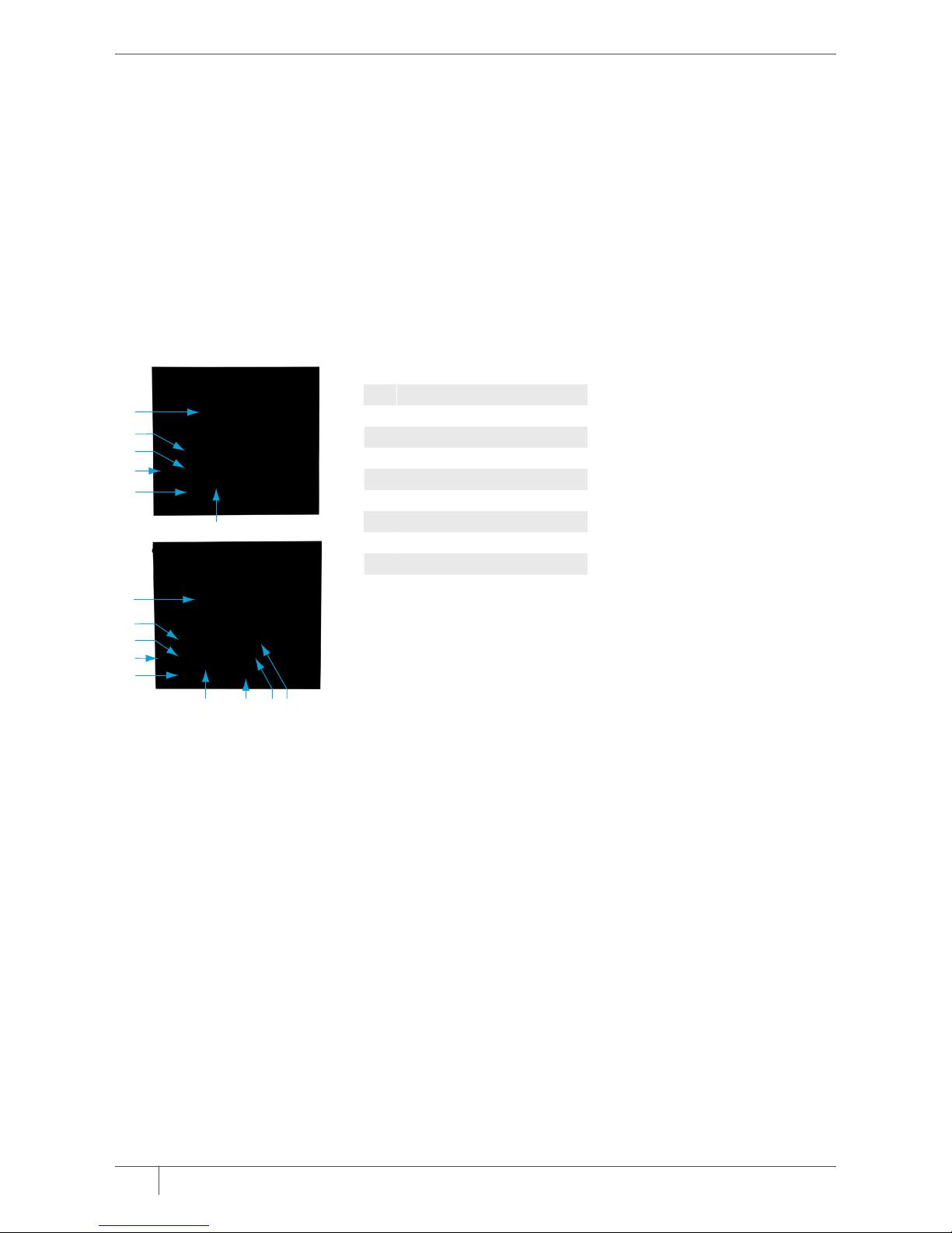
P-CTX: I/O CARD
Figure 12: P-CTX
Key to Figure 12
DESCRIPTION TYPE DETAILS
1 Fuse
2
4–20 mA differential pressure output GND
+
-
Output
Output
Output
Ground
24 VDC
0 VDC
3 Cycling
Remote indication of when a valve is being actuated.
Output
Common
Voltage free
Voltage free
4 Watchdog alarm
Indicates failure of microprocessor.
Output
Common
Voltage free
Voltage free
5 High dP alarm
Indicates that dP has reached the programmed alarm trigger.
Output
Common
Voltage free
Voltage free
6 Service alarm
Indicates that either 100K, 500K, or 950K cycles have been completed.
Output
Common
Voltage free
Voltage free
7 Coil failure alarm
Indicates solenoid failure on the system.
Output
Common
Voltage free
Voltage free
8 Auxiliary alarm
Indicates the alarm state of an auxiliary input device (see 14).
Output
Common
Voltage free
Voltage free
9 Power OK signal
Indicates system power is OK.
Output
Common
Voltage free
Voltage free
10 Isolate valve (for optional tube-cleaner function only)* Output
Common
24 V DC**
11 Purge valve (for optional tube-cleaner function only)* Output
Common
24 V DC**
12 Demand/Continuous switch
Allows remote switching between continuous and demand control modes (when P2 interface
is fitted).
Input
Common
Voltage free
Voltage free
13 Manual cycle
Forces a full cleaning cycle.
Input
Common
Voltage free
Voltage free
14 Auxiliary input
Allows the connection of an auxiliary device (e.g. pressure switch, broken bag detector, etc.).
Input
Common
Voltage free
Voltage free
15 Low header (tank pressure) alarm
Indicates low tank pessure, when connected to an appropriate pressure switch (not supplied).
Input
Common
Voltage free
Voltage free
16 Reset service alarm
Resets the service alarm signal.
Input
Common
Voltage free
Voltage free
17 Reset general alarm
Resets all alarms, with the exception of the service alarm.
Input
Common
Voltage free
Voltage free
Note:
The 4–20 mA output (2) is internally powered from the control system. No additional power supply is required.
* The Isolate and Purge functions are disabled on the P-CTX card when attached to the AC/AC baseboard only.
** Isolate and Purge contacts on the AC/AC baseboard have an output voltage equal to mains input voltage (110 V AC or 240 V AC).
INSTALLATION
OPTIONAL ACCESSORIES
2 3 4 5 6 7 8 9
1
10 11 12 13 14 15 16 17
Page 13

13INSTALLATION AND OPERATING INSTRUCTIONS PRECISION® FILTER CLEANING SYSTEM CONTROLS
BASIC INFORMATION
The P-CTX card provides voltage-free contacts for alarm outputs, basic remote control inputs and a 4–20 mA output for differential
pressure reporting (P2 only). Figure 2 shows the P-CTX mounted correctly on the left side of the baseboard. The table on page
12 provides a description of each I/O point, which may be connected to remote push-buttons, lights, sirens, data-loggers, control
panels and programmable logic controllers.
Voltage-free Outputs
The P-CTX provides a number of voltage-free output contacts that can be used for alarm reporting. Each alarm output consists
of an output terminal and a common terminal. Any voltage applied to the common terminal will be present on the output
terminal when the alarm is raised.
Voltage-free Inputs
The P-CTX provides a number of voltage-free input contacts that can be used for basic remote control of the P1 or P2. Each
input consists of an input terminal and a common terminal; bridging these two contacts triggers the corresponding function.
4–20 mA Output
The P-CTX features a 4–20 mA output that can be used for differential pressure reporting. The output consists of a ground terminal,
24 V DC terminal and 0 V DC. An output current of 4 mA corresponds to a dP = 0 kPa and 20 mA corresponds to a dP = 2.5 kPa.
The table over the page provides a description and details of each output terminal on the P-CTX.
P-MOD: MODBUS COMMUNICATIONS CARD
Figure 13:
P-MOD
1
2
3 4 5
Key to Figure 13
1 Switch for terminating resistor (DIP switch No.1)
2 Communications LED
3 Bus A (RS485+)
4 Bus B (RS485−)
5 GND (Ground/Drain)
BASIC INFORMATION
The P-MOD card is a network card which operates using the Modbus RTU communication protocol. Via the P-MOD the
controller can be connected to a DCS or SCADA system, allowing remote programming and monitoring of all menu items,
alarms and system details.
RS485 Modbus system specification is:
ITEM DETAIL
Protocol Modbus RTU
Hardware layer 2-wire, half-duplex RS485
Communications speed 9600 BPS
Stop bits 1
Data bits 8
Parity None
If the P-MOD is the last device connecting the Modbus RTU network, ensure DIP 1 of the terminating resistor switch (Figure 13,
item 1) is set to ‘ON’. This enables the 120 ohm resistor on the P-MOD; no separate resistor is required.
Page 14
14 INSTALLATION AND OPERATING INSTRUCTIONS PRECISION® FILTER CLEANING SYSTEM CONTROLS
POWERING UP THE SYSTEM
See Figure 1 (items 4 and 5). Moving the power switch into the on position will power up the Precision. The Power LED will light,
and the backlit interface display will light up.
The Precision performs a self-diagnostic routine, confirming all attached modules and reporting automatically all attached
solenoids and expansion cards. The Precision will then operate according to its programmed modes.
Note that the Precision automatically identifies all connected expansion cards, modules and solenoids. No programming is
required.
THE DISPLAY AND INTERFACE
Figure 14:
P1 and P2 Interfaces
4
1
2
6
5
3
7 8 9
4
1
2
6
5
3
Key to Figure 14
1 Backlit LCD
2 Previous menu item
3 Next menu item
4 Increment
5 Decrement
6 Enter
7 Alarm reset
8 Demand/Continuous mode toggle
9 Manual Cleaning Cycle
P1 – Continuous Control Interface
The P1 interface provides sequential and continuous pulse cleaning control. While in RUN mode, the two-line LCD will show:
Line 1: Scrolling display of system settings and alarms
Line 2: Time to next pulse (seconds)/Output ID of next pulse
P2 – Enhanced Demand Interface
The P2 interface provides cleaning on demand basis (i.e. in accordance with the differential pressure across the filters),
minimising air consumption and valve wear, and maximising filter life. The P2 also provides enhanced pulse-control functions,
including Pattern Cleaning and Maximum Interval between cleaning cycles.
While in RUN mode, the four-line LCD will show:
Line 1: Scrolling display of system settings and alarms
Line 2: Differential pressure and units (Pa, kPa, InWG, mm H2O, or mm Hg)
Line 3: Pulsing status (cycling, paused, stopped)
Line 4: Time to next pulse (seconds)/Output ID of next pulse
MANUAL ACTIVATION OF SOLENOID OUTPUTS
See Figure 1 (item 6) and Figures 3 and 4 (item 16).
Pushing the manual output triggers will power their corresponding output for 100 ms if there is a solenoid connected.
Simultaneously the output LED will light. Note that this function has been removed for all AC output boards to comply with
safety standards. Alternatively, pressing the manual cycle button on the P2 interface (Figure 14, item 9) will force a single
complete pulsing sequence for all baseboards, AC and DC output. This feature can be used for confirming valve operation
and diagnosing filter cleaning problems.
OPERATION
Page 15

15INSTALLATION AND OPERATING INSTRUCTIONS PRECISION® FILTER CLEANING SYSTEM CONTROLS
To enter programming mode, press Enter (Figure 14, item 6), followed by:
+ − − + Enter
UP (Figure 14, item 2), scroll to previous menu item; DOWN (Figure 14, item 3), scroll to next menu item.
P1 – CONTINUOUS CONTROL
Menu Structure
LEVEL 1 ENTRY LEVEL 2 MENU ITEM LEVEL 3 OPTIONS
1 Code
2
2a
2b
2c
2d
2e
Language
English
Italian
Spanish
German
French
3 Reset Factory Defaults
4 On Time
5 Off Time
6 Blowdown Cycles
7 Hour Counter
8 Number of Slaves
9 Total Cycles
10
10a
10b
Tube Cleaner*
Period
Duration
11 Network**
12 Run
* Available on the AC/AC baseboard, otherwise only when P-CTX is fitted.
** Only when P-MOD is fitted.
DESCRIPTION OF MENU ITEMS
Language
Precision may be run in one of five languages, as listed above.
Reset Factory Defaults
Puts all settings back to defaults (set at time of manufacture).
On Time
Sets electrical output duration between 30 and 500 ms.
Off Time
Sets pause between pulses between 1 s and 999 s.
Blowdown Cycles
Sets the number of off-line cleaning cycles to be executed after the dust collector fan is shut down. Off to 10 cycles. This only
operates when the fan contacts (Figure 2, item 12) are closed.
Hour Counter
Displays the total hours that the controller has been running for. Pressing [Enter] allows the hour counter to be reset.
Number of slaves
Displays the number of expansion cards connected to the system.
Total Cycles
Displays the total number of cycles completed. This will trigger a service alarm at 100 K, 500 K, and 950 K cycles. Pressing
[Enter] allows the cycle counter to be reset. 0 to 1 000 000 cycles.
PROGRAMMING AND
ADVANCED FEATURES
Page 16

16 INSTALLATION AND OPERATING INSTRUCTIONS PRECISION® FILTER CLEANING SYSTEM CONTROLS
Tube Cleaner
Available on the AC/AC baseboard, otherwise only when P-CTX is fitted. This allows the tube-cleaning parameters to be
specified: Select ON or OFF, then:
Period: The frequency of the tube-cleaning pulse. 1 to 999 minutes.
Duration: The duration of the tube-cleaning pulse. 1 to 60 seconds. This feature is used to control the pulse cleaning of the
differential pressure-sensing lines. In the case of the P1 with P-CTX, these may be used to clear the pressure lines of third-party
pressure gauges installed on the dust collector.
Network
Allows the network address to be set for controllers running on a DCS. Values 0 to 255, and OFF. Setting to OFF takes the
Precision off the network.
Run
Returns the controller to operating mode.
P2 – ENHANCED DEMAND CONTROL
Menu Structure
LEVEL 1 ENTRY LEVEL 2 MENU ITEM LEVEL 3 SUB-MENU OPTIONS LEVEL 4 OPTIONS
1 Code
2
2a
2b
2c
2d
2e
Language
1
English
Italian
Spanish
German
French
3 Factory Defaults
1
4 On Time
1
5 Off Time
1
6
6a
6b
6c
6d
6e
Display Units
kPa
Pa
in WG
mm H20
mm Hg
7
7a
7ai
7aii
7b
7bi
7bii
Demand Cleaning
Limits
Bandwidth
Low dP
High dP
High dP
Bandwidth %
8 Alarm Delay
9 High dP Alarm
10 Precoating
11 Pattern Cleaning
12 Blowdown Cycles
1
13
13a
13b
Remote Stop
Hardwired
Automatic
14
14a
14b
Tube Cleaner
1
*
Period
Duration
15 Maximum Interval
16 Hour Counter
1
17 Number of Slaves
1
18 Total Cycles
1
19 Network1**
20 Run
1
1
As described for the P1 interface.
* Available on the AC/AC baseboard, otherwise only when P-CTX is fitted.
** Only when P-MOD is fitted.
Page 17

17INSTALLATION AND OPERATING INSTRUCTIONS PRECISION® FILTER CLEANING SYSTEM CONTROLS
DESCRIPTION OF MENU ITEMS (P2 SPECIFIC)
Display Units
Allows the display units for pressure to be set to one of five commonly used measures. See table above. The selected units will
then be used for all differential pressure-related settings, and network reporting via P-MOD.
Demand Cleaning
Allows the parameters associated with demand cleaning control to be specified.
Limits
High dP – The differential pressure at which pulse cleaning is to start.
Low dP – The differential pressure at which pulse cleaning is to stop. Alternatively:
Bandwidth
High dP – The differential pressure at which cleaning is to start. (up to 10″ WG or 2.49 kPA) Bandwidth % – The % range in which
the differential pressure is to be maintained (5 to 50%).
Alarm Delay
Used in conjunction with High dP Alarm, this allows the specification of a delay before an alarm is triggered. This can be used to
eliminate false alarms caused by spikes in the pressure readings. 255 seconds maximum delay.
High dP Alarm
Assigns the differential pressure at which a high dP alarm is to be triggered. Maximum value is 10″ WG or 2.49 kPa.
Precoating
Allows filter seeding/precoating before the controller moves into its regular cleaning program mode. This is specified by a
differential pressure value at which the regular cleaning program is to activate. Maximum value is 10
″ WG or 2.49 kPA.
Pattern Cleaning
This allows the selection of a pulse-cleaning pattern to minimise dust re-entrainment. Selecting a cleaning pattern allows
solenoids to be wired in a sequential manner to the controller outputs, while pulsing in a non-sequential manner. Three options
are available: OFF, SKIP 1, SKIP 2.
With baseboard outputs only, valves fire in the following sequence:
OFF 1, 2, 3, 4, 5, 6, 7, 8, 9, 10
SKIP 1 1, 3, 5, 7, 9, 2, 4, 6, 8, 10
SKIP 2 1, 4, 7, 10, 2, 5, 8, 3, 6, 9
Where expansion cards are connected (example below shows 2 cards connected):
OFF 1 … 10, 1C1 … 10C1, 1C2 … 10C2
SKIP 1 1M, 1C1, 1C2, 3M, 3C1, 3C2, 5M, 5C1, 5C2, 7M, 7C1, 7C2, 9M, 9C1, 9C2, 2M, 2C1, 2C2, 4M, 4C1, 4C2, …
SKIP 2 1M, 1C1, 1C2, 4M, 4C1, 4C2, 7M, 7C1, 7C2, 10M, 10C1, 10C2, 2M, 2C1, 2C2, 5M, 5C1, 5C2, 8M, 8C1, 8C2, …
M refers to baseboard output; C1 refers to expansion card 1; C2 refers to expansion card 2.
Remote Stop
Used in conjunction with Blowdown Cycles. This allows the blowdown cycles trigger to be selected from either:
Hardwired – blowdown cycles are started when the fan contacts are closed (Figure 2, item 12).
Automatic – blowdown cycles are started when differential pressure drops to a set value (0.1 to 2.0 kPa or 0.4 to 8.0″ Wg).
No electrical connections to the dust collector fan are required. If the dP rises above the set value, normal operation resumes
regardless of the number of blowdown cycles completed.
Maximum Interval
Only functions when the P2 is in Demand cleaning mode. This specifies a maximum pause duration between pulsing cycles
when in Demand mode. This may be set to OFF, or from 1 minute to 999 minutes. When the cycle is triggered on the basis of
Maximum Interval, one complete cleaning cycle is executed. This mode can act as a backup cleaning mode when differential
pressures do not rise to the preset level for cleaning to commence, or when there is a blockage or leak in the differential
pressure-sensing lines.
Page 18

18 INSTALLATION AND OPERATING INSTRUCTIONS PRECISION® FILTER CLEANING SYSTEM CONTROLS
MESSAGES
Scrolling Display
DISPLAY DESCRIPTION
Model xx.xx Software version number
Continuous Mode
P2
Controller is in Continuous Mode
Demand Mode
P2
Controller is in Demand Mode
On Time = xxx ms Electrical On Time of Solenoid
Off Time = xxx sec Electrical Off Time of Solenoid
Slaves = xxxx Number of Slaves connected to Controller
Blowdown cycles = xxxx Number of complete cleaning cycles the controller performs after the fan has been switched off
Remote Stop = Hardwired
P2
Remote Stop is hardwired to the fan or circuit breaker
Remote Stop = Automatic
P2
Remote Stop is dependent on dP of system
Hour Counter = xxHrs Number of hours the controller has been operational
Total Cycles = xxxxxx Number of complete cleaning cycles the controller has performed
Max. Interval = xxx
P2
The maximum time that can elapse before a cleaning operation takes place (only in use when in
Demand Mode)
Pattern Cleaning = xxx
P2
Allows the controller to ‘Off’, ‘Skip 1’ or ‘Skip 2’ outputs (refer to cleaning patterns)
Alarm Delay = xxx sec
P2
Delays high dP and Auxiliary Alarm for this amount of time to avoid false alarms due to system spikes,
etc.
Tube Cleaner = xxxx ‘Off’, ‘Tube Cleaner Duration’ and ‘Tube Cleaner Period’
Units = xxx
P2
Current units being used for display of dP
P2
Only for the P2 interface.
General Messages
DISPLAY DESCRIPTION
dP = xxxx (units)
P2
Current dP
Stopped (dP)
P2
Remote Stop due to Automatic Blowdown dP measurement
Stopped (Fan) Remote Stop due to Hardwired Blowdown
Manual Cycle
P2
Either the Manual Cycle button or contact (P-CTX) has been activated. The controller is now performing
one complete cleaning cycle with the programmed On and Off Time.
Cycling – Paused
P2
Controller waiting for dP to exceed High dP Limit value
Cycling –(Precoating)
P2
Controller waiting for dP to exceed Precoating value
xxx sec Countdown to next solenoid operation
xx:xx Next SLAVE# : OUTPUT# to operate
Tube Cleaner xx sec Controller is performing a Tube Clean operation with xx sec remaining
P2
Only for the P2 interface.
MESSAGES AND ALARMS
Page 19

19INSTALLATION AND OPERATING INSTRUCTIONS PRECISION® FILTER CLEANING SYSTEM CONTROLS
Alarm Messages
DISPLAY DESCRIPTION
Coil OC Fail – xx:yy* Coil yy on Slave xx has failed Open Circuit – Replace coil.
Coil CC Fail – xx.yy* Coil yy on Slave xx has failed Closed Circuit – Replace coil.
Low Coil Voltage – xx.yy Voltage outside the recommended voltage is being delivered to the coil yy on Slave xx or to the
baseboard – check connections.
Slave Removed – xx Slave xx has been lost since power-up – Check connections.
Over Temperature – Slowed Power Supply is warm. Off Time has been increased to allow the Power Supply to return to normal.
Over Temperature – Stopped Power Supply is hot. Controller has ceased to function to allow the Power Supply to return to normal
temperature. The controller will then automatically operate.
Power Supply Low Power Supply voltage is below the minimum voltage. Once voltage is within operating range, the
controller will automatically operate normally.
Stop (Over Temp) Power Supply is hot. Controller has ceased to function to allow the Power Supply to return to normal
temperature. The controller will then automatically operate.
Bad MOD board xx A faulty ‘plug-in’ board has been identified as number xx where xx is:
3. P-CTX
4. P-MOD
Contact Goyen for replacement board.
Unknown Fault xx Firmware Error – Contact Goyen.
Exception # xx Contact Goyen with Exception category # and Exception number xx – Contact Goyen.
1. P2 interface Board requires calibration
2. Could not communicate to baseboard slave (may indicate problem with external slave bus, but most
likely a problem with the micro or the RS485 comms on the baseboard; other options are a fault on
the micro on the P1/2 interface or possibly the 50-way cable).
3. 3.3 V rail is low (< 3 V) – this message indicates a fault in the 3V3 supply on the baseboard.
Aux. Alarm Auxiliary Alarm is present (P-CTX must be present).
Low Header P Insufficient compressed-air pressure exists in header. Solenoid operation is ceased until pressure is at
acceptable levels once again (P-CTX must be fitted).
Service Alarm 100 000 cycles 100 000 complete cleaning cycles have been completed – Check control system parameters.
Service Alarm 500 000 cycles 500 000 complete cleaning cycles have been completed – Check condition of filter elements.
Service Alarm 950 000 cycles 950 000 complete cleaning cycles have been completed – Replace kits in valves.
* In the case of solenoid failure, all other solenoids will continue to operate. Alarm will be automatically cancelled on connection of a good
solenoid to the output in question.
Page 20

20 INSTALLATION AND OPERATING INSTRUCTIONS PRECISION® FILTER CLEANING SYSTEM CONTROLS
The Precision is programmed with system self-diagnostics. Most issues can be resolved by reference to the system messages
and alarms present on the interface and listed in the previous section, ‘Messages and Alarms’. For issues which cannot be
resolved in this way, refer to the table below or contact your system supplier.
General/Startup
SYMPTOM CAUSE RESOLUTION
System does not power up. Power LED
remains off.
Power is not connected to the baseboard.
Power wiring is incorrect.
Power supplied is below the minimum
required to operate the controller.
Ribbon cable to P1 or P2 interface is loose.
Blown fuse.
Defective on-board power supply or interface.
Check connection.
Check wiring to socket is in accordance with
this manual.
Check power supply is within tolerance.
Check and ensure fit to interface and
baseboard is secure.
Replace fuse.
Contact your supplier.
Some or all expansion cards are not detected
on startup.
Cabling between expansion cards and the
baseboard is incorrect.
Broken cabling between expansion cards and
the baseboard.
Damaged fuse on expansion card or
baseboard.
Check connections are in accordance with
this manual.
Replace cable.
Replace fuse.
Some or all connected solenoids are not
detected on startup.
Cabling between expansion cards and the
baseboard is incorrect.
Broken cabling between expansion cards and
the baseboard.
The common terminals between each bank
of solenoids (or between solenoids) are not
linked or returned to the common terminal
on the relevant baseboard or expansion card.
The solenoid active terminal is not properly
linked to its relevant system output terminal.
Damaged fuse on expansion card or
baseboard.
Check connections are in accordance with
this manual.
Replace the cable.
Ensure commons are linked.
Check connections and repair if necessary.
Replace fuse.
TROUBLESHOOTING
Page 21

21INSTALLATION AND OPERATING INSTRUCTIONS PRECISION® FILTER CLEANING SYSTEM CONTROLS
Operational
SYMPTOM CAUSE RESOLUTION
P2 does not go into cleaning mode on
startup. Display shows: ‘Precoating’.
Valves do not pulse.
P2 is waiting for differential pressure to rise
above the factory preset Precoating value
(1.5 kPa, 6″ WG) or the user set value.
Enter the menu and set Precoating to off, or
wait for differential pressure to rise.
P2 does not go into cleaning mode on
startup. Display shows: ‘Stopped (dP)’. Valves
do not fire.
P2 is waiting for differential pressure to
rise above the factory preset Remote Stop
trigger value (0.5 kPa or 2″
WG) to commence
operation.
Enter the menu and set remote stop dP to
the preferred value or to ‘Hardwired’, or wait
for the dP to rise.
P2 does not go into cleaning mode on
startup. Display shows: ‘Stopped (FAN)’.
Valves do not pulse.
Fan contacts are closed on the baseboard. Check wiring to fan contacts; if the fan or
another circuit breaker is not connected
to the Precision, the fan contact terminals
should be open.
If the fan is connected to the baseboard,
check that the contacts at the fan are
normally open type, and check the wiring.
Valves on multiple expansion boards
are firing simultaneously. The outputs
correspond to each other.
Two or more expansion cards are set with the
same address.
Check each output is assigned a unique
address.
Expansion cards are not pulsing sequentially
(Pattern cleaning mode is off).
Expansion card addresses have not been
assigned in sequential order.
Re-assign expansion card addresses in
numerical order.
P-MOD Modbus Communications
SYMPTOM CAUSE RESOLUTION
System is not recognised on the DCS or
plant SCADA system. P-Mod is recognised
by Precision on startup.
Modbus communications is turned OFF in the
menu. Diagnostics on startup will indicate
Network is OFF.
Network address of controller is incompatible
with address assigned at DCS level.
Enter the menu, and at the network menu
item ensure the network is given an address,
rather than set to off.
Check address setting on the Precision
matches the DCS.
Page 22

22 INSTALLATION AND OPERATING INSTRUCTIONS PRECISION® FILTER CLEANING SYSTEM CONTROLS
ELEMENT DETAILS
P2 on-board pressure transducer Operating Pressure Range: 0 to 2.5 kPa (0 to 10″ WG)
Accuracy: +/−2.5% FSS
Burst pressure: 20 kPa (83″ WG)
Vibration resistance: to 10 G at 20–2000 Hz
Response time: 8 ms
Temperature-compensated ASIC signal conditioning
DC/DC baseboard
Input voltage: 24 to 48 V DC (+/−10%)
Input current: 3 A maximum
Permissible transients: 60 V maximum
AC/AC baseboard Input voltage: 110 or 240 V AC (+/−10%) 50/60Hz
Input current: 3 A maximum
Permissible transients: 300 V maximum
AC/DC baseboard Input voltage: 110 to 240 V AC (+/−10%) 50/60Hz
Input current: 2 A maximum
Permissible transients: 300 V maximum
DC Output terminals Voltage: 24 V DC
Output current: 2.5 A maximum
10 on baseboard, 10 on each expansion card
AC Output terminals Voltage: Equal to input voltage
Output current: 2.4 A
10 on baseboard, 10 on each expansion card
Maximum number of expansion 19 giving 200 outputs total cards connected
Maximum distance between 100m expansion cards
Tube cleaner output (P-CTX) AC/DC or DC/DC baseboard
Voltage: 24 V DC
Output current: 2.5 A maximum
Tube cleaner output (P-CTX) on AC/AC baseboard Voltage: Equal to input voltage
Output current: 2.4 A
Analogue output (P-CTX) Type: Internally powered 4–20 mA
Voltage: 24 V DC
Output current: 20 mA maximum
Digital I/O (P-CTX) Type: Voltage-free (dry) contacts
Maximum applied voltage: 300 V AC
FAN & GND contacts (baseboard) Type: Voltage-free (dry) contacts
Maximum applied voltage: 300 V AC
RS485 contacts (P-MOD) Type: Data
Maximum applied voltage: 24 V DC
Modbus implementation Layer: 2-wire, half-duplex, RS485 serial
Protocol: Modbus RTU
Baud Rate: 9600
Data bits: 8
Stop Bits: 1
Parity: None
Address range: 0–255
System safe operating temperature 0 to 70°C (32 to 158°F)
System humidity allowance Non-condensing to 85%
PRECISION SYSTEM
SPECIFICATIONS
Page 23

23INSTALLATION AND OPERATING INSTRUCTIONS PRECISION® FILTER CLEANING SYSTEM CONTROLS
REGISTER DEFINITIONS P-MOD (MODBUS)
Page 24

24 INSTALLATION AND OPERATING INSTRUCTIONS PRECISION® FILTER CLEANING SYSTEM CONTROLS
REGISTER DEFINITIONS P-MOD (MODBUS)
Page 25

25INSTALLATION AND OPERATING INSTRUCTIONS PRECISION® FILTER CLEANING SYSTEM CONTROLS
REGISTER DEFINITIONS P-MOD (MODBUS)
Page 26

26 INSTALLATION AND OPERATING INSTRUCTIONS PRECISION® FILTER CLEANING SYSTEM CONTROLS
REGISTER DEFINITIONS P-MOD (MODBUS)
Page 27

27INSTALLATION AND OPERATING INSTRUCTIONS PRECISION® FILTER CLEANING SYSTEM CONTROLS
REGISTER DEFINITIONS P-MOD (MODBUS)
Page 28

Goyen Precision Inst-Ops Manual Rev02 11/14
CLEANAIRSYSTEMS.COM
© 2014 Pentair Clean Air Systems reserves the right to change product designs and specifications without notice.
 Loading...